International Journal of Emerging Technology and Advanced Engineering
Website: www.ijetae.com (ISSN 2250-2459,ISO 9001:2008 Certified Journal, Volume 4, Issue 3, March 2014)
194
Performance Evaluation of Back to Back E-Shape Microstrip
Patch Antenna for MIMO Applications
Prajakta Doiphode
1, Sharad Wagh
21,2MPSTME (NMIMS), MPSTME, NMIMS University, Bhakti Vedant Swami Marg, JVPD Scheme, Vile-Parle (W),
Mumbai -400056
Abstract— A back to back E-shaped rectangular microstrip
patch antenna for obtaining circular polarization with an axial ratio of 2.5 dBi for Multiple Input Multiple Output (MIMO) applications is designed using IE3D software from Zeland. The microstrip patch antenna is constructed using a single layer RT/duroid (5880) substrate, having dielectric constant εr = 2.2 and loss tangent tan δ =0.001. A 2x2 MIMO is developed using the proposed antenna for improved channel capacity having a bandwidth of 2.097 GHz and a return loss of -50 dB.
Keywords—MSA, Circular polarization, MIMO, Wi-MAX, WLAN.
I. INTRODUCTION
MIMO (Multiple Input Multiple Output) systems are capable of achieving higher data rates by using multiple antennas at both the transmitter and receiver instead of a single antenna at the respective locations without using additional bandwidth or an increase in the respective power [1].Recent studies have shown that the multiple input multiple output (MIMO) system is a promising solution to meet the needs of the growing demands for higher data rates, higher channel capacity and a more spectrum efficient wireless communications system.
MIMO systems are very much suitable for the present and emerging communication systems like Wi-Fi, WLAN, and 4G. This has led to extensive work to design antennas that can optimize the MIMO system performance. The MIMO antennas mainly aim at minimizing the effect of mutual coupling that degrades the performance of the communication systems. Lesser the mutual coupling greater is the efficiency of the antenna. [2] The mutual coupling can be decreased by adjusting the distance between the antenna elements.
Microstrip patch antennas are an ideal choice for the development of such systems and have been well known for its advantages such as light weight, low fabrication cost, mechanically robust when mounted on rigid surfaces and capability of dual and triple operating frequencies. [3]
Various approaches have been taken to suit the need of
wireless communication applications including
modification of substrate parameters and the patch shape.
Traditional antenna designs yields circular polarization by either inserting perturbation elements at the boundary of a circular patch or by cutting diagonal slots along the patch. [4] Circular polarization has been observed typically in circular, square and triangular microstrip patches.
In this paper a rectangular patch having a total area 344
mm2 cut into an E-shape joined back to back having
reduced total radiating area 256.8 mm2 design has been
proposed with the sides of the patch being truncated. A 2X2 MIMO array antenna design for reduced mutual coupling and improved channel capacity is further
proposed. Experimental geometry of the single element
antenna and the two element MIMO array, the simulated results for the both yielding circular polarization, improved return loss and bandwidth are presented and discussed.
II. MATHEMATICAL ANALYSIS
To design a rectangular microstrip patch antenna following parameters such as dielectric constant (εr), resonant frequency (fr), and height of the substrate (h) should be considered for calculating the length and the width of the patch [5].
Width of patch (w ).
(1.1)
Effective dielectric constant of antenna is
(1.2)
Effective dielectric length of antenna is
(1.3)
The extended length (ΔL) of antenna is
International Journal of Emerging Technology and Advanced Engineering
Website: www.ijetae.com (ISSN 2250-2459,ISO 9001:2008 Certified Journal, Volume 4, Issue 3, March 2014)
195
III. ANTENNA DESIGN
[image:2.612.334.542.263.426.2]The antenna design is shown in fig.1 proposed back to back rectangular microstrip patch antenna having dimension length (L) 17.2mm, width (W) 20mm, and thickness (h) 3.2mm. The substrate of the patch is RT/ duroid 5880 having dielectric constant = 2.2. [6] The back to back E-shape patch is truncated along the corners. The corners of the patch are truncated such that a square slot of 4*4 dimension with 45 degree rotation is obtained. The patch is provided with a co-axial feed.
Figure 1: Geometry of the proposed antenna
TABLE I
OPTIMIZED ANTENNA PARAMETER
Antenna Parameter Value
Dielectric constant 2.2
Thickness(h) 3.2 mm
Length(L) 17.2 mm
Width(W) 20 mm
Cut width d1 2 mm
Cut length d2 6 mm
Cut width W1 5.9 mm
Cut width Ws 6.2 mm
Cut length Ls 5 mm
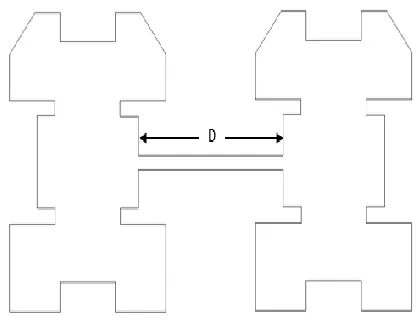
The proposed antenna simulated using IE3D simulator resonates at a dual band of 7.5 GHz and 8.6 GHz. The antenna design shown in fig.2 is the proposed 2x2 MIMO system developed using the back to back E-shaped corner truncated microstrip patch antenna. The separation between the elements for the proposed design is taken to be 10mm. The dimensions for the proposed design are taken to be the same as that of the single back to back E-shaped corner truncated microstrip patch antenna.
Figure 2: Geometry of the proposed 2x2 MIMO antenna
The proposed antenna simulated using IE3D software from Zeland yields circular polarization and improved return loss.
IV. RESULT AND DISCUSSION
[image:2.612.50.288.299.672.2]International Journal of Emerging Technology and Advanced Engineering
Website: www.ijetae.com (ISSN 2250-2459,ISO 9001:2008 Certified Journal, Volume 4, Issue 3, March 2014)
[image:3.612.325.565.145.568.2]196 A. Smith Chart
Figure 3: Smith chart
[image:3.612.58.265.159.383.2]B. Return Loss Measurement
Figure 4: Return loss v/s Frequency
Return loss = -17 dB at 7.5 GHz
Return loss = -20 dB at 8.6 GHz
C. VSWR Measurement
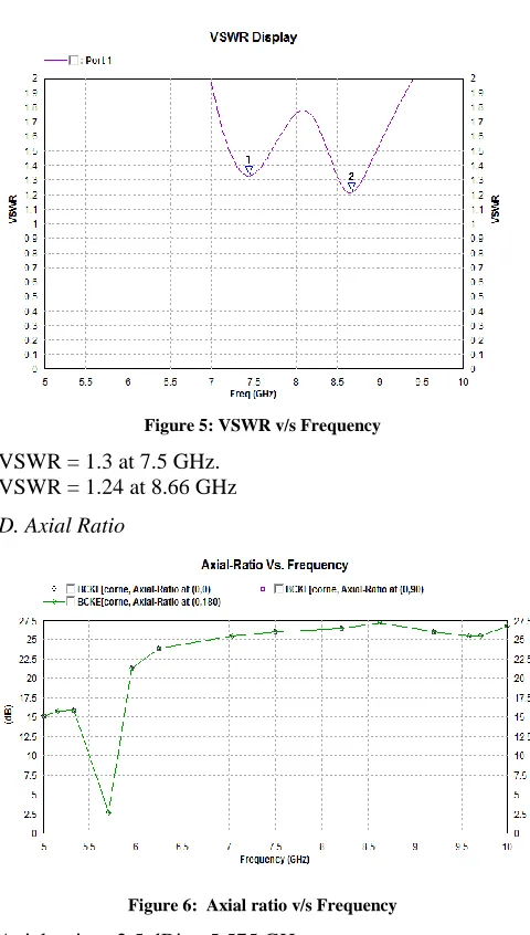
Figure 5: VSWR v/s Frequency
VSWR = 1.3 at 7.5 GHz. VSWR = 1.24 at 8.66 GHz
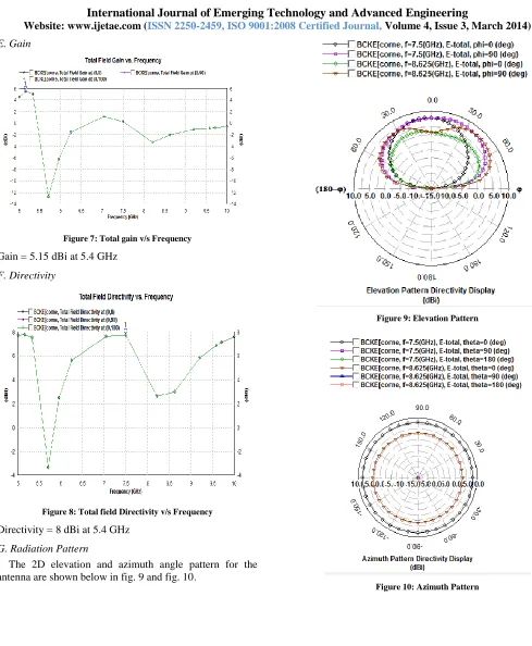
[image:3.612.329.551.162.336.2]D. Axial Ratio
Figure 6: Axial ratio v/s Frequency
International Journal of Emerging Technology and Advanced Engineering
Website: www.ijetae.com (ISSN 2250-2459,ISO 9001:2008 Certified Journal, Volume 4, Issue 3, March 2014)
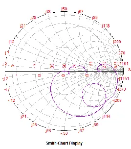
[image:4.612.51.540.100.694.2]197 E. Gain
Figure 7: Total gain v/s Frequency
Gain = 5.15 dBi at 5.4 GHz
[image:4.612.339.543.131.663.2]F. Directivity
Figure 8: Total field Directivity v/s Frequency
Directivity = 8 dBi at 5.4 GHz
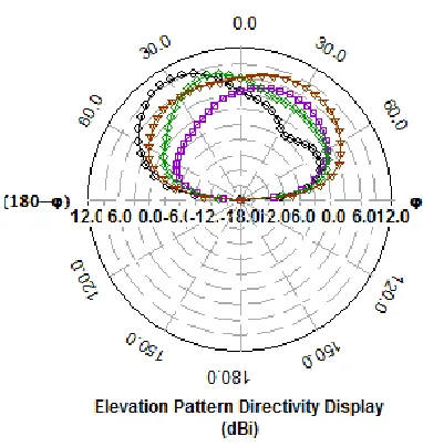
G. Radiation Pattern
[image:4.612.55.278.157.305.2]The 2D elevation and azimuth angle pattern for the antenna are shown below in fig. 9 and fig. 10.
Figure 9: Elevation Pattern
[image:4.612.55.278.365.555.2]International Journal of Emerging Technology and Advanced Engineering
Website: www.ijetae.com (ISSN 2250-2459,ISO 9001:2008 Certified Journal, Volume 4, Issue 3, March 2014)
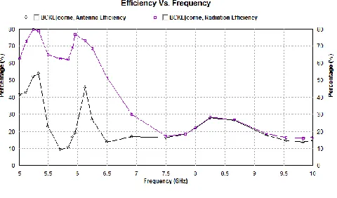
198 H. Antenna Efficiency and Radiation Efficiency
[image:5.612.328.560.155.327.2]The antenna and radiation efficiency are shown below in fig. 11.
Figure 11: Efficiency
Antenna efficiency = 60% Radiation efficiency=80%
The 2x2 MIMO antenna design is simulated using IE3D software from Zeland. The antenna yields circular polarization and a better return loss compared to that of the 1x1 back to back E-shaped microstrip patch antenna.
[image:5.612.55.278.172.345.2]I. 2x2 MIMO antenna Smith chart
Figure 12: 2x2 MIMO Antenna Smith Chart
[image:5.612.328.557.384.559.2]J. 2X2 MIMO Antenna Return Loss Measurement
Figure 13: 2x2 MIMO Antenna Return Loss v/s Frequency
Return loss = -50 dB at 7.8 GHz
K. 2X2 MIMO Antenna VSWR Measurement
Figure 14: 2x2 MIMO Antenna VSWR v/s Frequency
[image:5.612.97.231.457.609.2]International Journal of Emerging Technology and Advanced Engineering
Website: www.ijetae.com (ISSN 2250-2459,ISO 9001:2008 Certified Journal, Volume 4, Issue 3, March 2014)
[image:6.612.54.287.137.314.2]199 L. 2X2 MIMO Antenna Axial Ratio
Figure 15: 2x2 MIMO Antenna Axial Ratio v/s Frequency
Axial ratio = 1.4 dBi at 5.575 GHz
[image:6.612.324.568.155.309.2]M. 2X2 MIMO Antenna Gain
Figure 16: 2x2 MIMO Total gain v/s Frequency
Gain = 7.5 dBi at 5.4 GHz
[image:6.612.48.295.347.528.2]N. 2X2 MIMO Antenna Directivity
Figure 17: 2x2 MIMO Total directivity v/s Frequency
Directivity = 10 dBi at 7.5 GHz
O. 2x2 MIMO Radiation Pattern
The 2D elevation and azimuth angle pattern for the antenna are shown below in fig. 18 and fig. 19.
[image:6.612.322.513.451.653.2]International Journal of Emerging Technology and Advanced Engineering
Website: www.ijetae.com (ISSN 2250-2459,ISO 9001:2008 Certified Journal, Volume 4, Issue 3, March 2014)
[image:7.612.67.252.135.398.2]200
Figure 19: 2x2 MIMO Antenna Azimuth Pattern
[image:7.612.52.292.438.579.2]P. 2x2 MIMO Efficiency
Figure 20: 2x2 MIMO Efficiency
Antenna efficiency = 55%
Radiation efficiency=80%
V. CONCLUSION
The design of back to back E-shaped corner truncated microstrip patch antenna can be widely used in MIMO applications. A single modified back to back E-shaped microstrip antenna design technique using coaxial feed was presented.
A 2x2 MIMO design technique yielding circular polarization and improved return loss and bandwidth was presented. The 1x1 and 2x2 MIMO system microstrip patch antenna is designed and the results are justified by simulating using IE3D simulator. The optimized antenna parameter results show that the 1x1 MIMO system antenna yields circular polarization having an axial ratio of 2.5 dBi, VSWR 1.3, 1.24 at 7.5 GHz, 8.66 GHz respectively. Return loss of about -17 dB at 7.5 GHz and -20 dB at 8.66 GHz was observed. The 2x2 MIMO antenna design yields circular polarization having an axial ratio of 1.4 dBi. An improved return loss as compared to that of the 1x1 back to back E-shape microstrip antenna of about -50 dB was obtained. The antenna has a bandwidth of 2.097 GHz. Antenna efficiency for the 2x2 MIMO system was observed to be 55% at 5.4 GHz while the radiation efficiency was observed to be 80% at 5.4 GHz.
REFERENCES
[1] Foschini, G. J. and M. J. Gans, ―On limits of wireless communications in a fading environment when using multiple antennas,‖ Wirel. Pers. Commun., Vol. 6, No. 3, 311– 335, 1998. [2] Abouda, A. A. and S. G. H¨ aggman, ―Effect of mutual coupling
capacity of MIMO wireless channels in high SNR scenario,‖ Progress In Electromagnetics Research, PIER 65, 27–40.
[3] M.B.Kadu, R.P.Labade, A.B.Nandgaonkar ,―Analysis and Designing of E-Shape Micro strip Patch Antenna for MIMO Application‖, International Journal of Engineering and Innovative Technology (IJEIT) Volume 1, Issue 2, February 2012.
[4] X.L. Sun J. Zhang, ―A Small patch antenna using CRLH TL unit cell‖, IEEE 2012.
[5] C.A. Balanis, Chapter 14 Microstrip Patch Antenna ―Advanced Engineering Electromagnetic‖, John Wiley & sons, New York, 1989. [6] P.Naveen Kumar, K.M.Vijay, T.Srinivas, K.Jagadeesh Babu , ―A Modified Back to Back E-Shaped Patch Antenna for 4G MIMO Communications‖,International Journal of Engineering and Technology Volume 2 No. 3, March, 2012.
[7] M. A. Jensen, J. W. Wallace, ―A review of antennas and propagation for MIMO wireless communications‖, IEEE Trans. Antennas Propagation., vol. 52, pp. 2810-2824, Nov. 2004.
[8] Anil.B. Nandgaonkar and Shankar B. Deosarkar,‖Broadband Stacked Patch Antenna for Bluetooth Applications‖, Journal of Microwaves, optoelectronics and electromagnetic applications, vol 8, June 2009.
[9] B.-K. Ang and B.-K. Chung,― A Wideband Microstrip Patch Antenna for 5-6GHz Wireless Communications‖, Progress In Electromagnetics Research, PIER 75, 397–407, 2007.
[10] J. R. James and P .S. Halls, Eds,. ―Handbook of Mirostrip antennas‖, London UK..: Peter Perigrinus, 1989, Ch. 1.