Honeywell
MULTICS SOFTWARE
RECONFIGURA TION
Honeywell
RECONFIGURATIONPROGRAM LOGIC MANUAL
MULTICS
RESTRICTED DISTRIBUTION
SUBJECT:
Dynamic Reconflguration Software for the Major Hardware Modules (Processor, System Controller, and Bulk Store).
SPECIAL INSTRUCTIONS:
DATE:
This Program Logic Manual (PlM) describes certain internal modules
constituting the Multlcs System. It is intended as a reference for only
those who are thoroughly famil iar with the implementation details of the
Multlcs operating system; interfaces described herein should not be used by
appl icatlon programmers or subsystem writers; such programmers and writers
are concerned with the external interfaces only. The external interfaces
are described in the Multics Programmers' Manual, Commands .2.QQ Active
Functions (Order No. AG92), Subroutines (Order No. AG93), and Subsystem
Writers' Guide (Order No. AK92).
As Multlcs evolves, Honeywell will add, delete, and modify module
descriptions In subsequent PLM updates. Honeywell does not ensure that the
internal functions and internal module interfaces will remain compatible
with previous versions.
This PLM is one of a set, which when complete, will supersede the System
Programmers' Supplement to the Multics Programmers' Manual (Order No.
AK96) •
THE INFORMATION CONTAINED IN THIS DOCUMENT IS THE EXCLUSIVE
PROPERTY OF HONEYWELL INFORMATION SYSTEMS. DISTRIBUTION IS
LIMITED TO HONEYWELL EMPLOYEES AND CERTAIN USERS AUTHORIZED
TO RECEIVE COPIES. THIS DOCUMENT SHALL NOT BE REPRODUCED OR
ITS CONTENTS DISCLOSED TO OTHERS IN WHOLE OR IN PART.
PREFACE
Multics Program Logic Manuals (PLMs) are intended for use by
Multics system maintenance personnel, development personnel, and
others who are thoroughly famil iar with Multics internal system
operation. They are not intended for appl ication programmers or
subsystem writers.
The PLMs contain descriptions of modules that serve as
internal interfaces and perform special system functions. These
documents do not describe external interfaces, which are used by
appl ication and system programmers.
Sin c e i n t e rna 1 i n t e r f ace s are add ed, del e ted , an d mod i fie d
as design improvements are introduced, Honeywell does not ensure
that the internal functions and internal module interfaces will
remain compatible with previous versions. To help maintain
accurate PLM documentation, Honeywell publ ishes a special status
bulletin containing a 1 ist of the PLMs currently available and
identifying updates to existing PLMs. This status bulletin is
distributed automatically to all holders of the. System
Programmers' Supplement to the Multics Programmers' Manual (Order No. AK96) and to others on request. To get on the mail ing 1 ist for this status bulletin, write to:
Large Systems Sales Support Multics Project Office
Honeywell Information Systems Inc. Post Office Box 6000 (MS A-85) Phoenix, Arizona 85005
@)
1974, Honeywell Information Systems Inc. File No.: 2L13Section
Sec t i on I I
Section I I I
Section IV
Sect i on V
Section VI
Sec t i on V I I
Sect i on V I I I
Section IX
CONTENTS
Page
Introduction • • • • • ., • • • • • • 4t • • • • • II • • • • • • • • • • 1-1
Terminology .•....•...•..•...•••••.•.•• 2-1
Data Structures .•.•...•...•...•.•. 3-1
The System Controller Addressing
S e gme n t • • . . . • . . . • • . . . • . . . . • • . . . . .. 3 - 8
The System Segment Table (SST) and
Related Data •..•...•....•.•..•...•• 3-8
Data Base Initialization ...•...•.•• 4-1 SCS Initialization . . . • . . . 4-1 SCAS Initialization . . . 4-2
SST Initialization .••..•...•.••.•... 4-2
Other Data Base Initialization .•...••• 4-3
Reconfig and Reconfigure ...•...••••• 5-1
Processor Reconflguration .•.•...•..•.••••.• 6-1
Idle Processes ...•...•...•...•••..•.•• 6-1
Adding a Processor to the System ...•. 6-2
Deleting a Processor from the System •••• 6-4
Memory Reconfiguration . . . • • . . 7-1 Adding a System Controller to the System 7-1 Removing a System Controller from the
S y 5 t em ... ~ •• 7 - 2 Automatic Memory Deletion ... to be supplied
Bulk Store Reconfiguration . . . • . 8-1 Adding Bulk Store Records . . . 8-3
Deleting Bulk Store Records ...•...• 8-3
Automatic Paging Device Record Removal •• 8-5
SECTION I
INTRODUCTION
This document describes the implementation and design of the
Multics dynamic reconfiguration software for the major hardware
modules of the system. Although there are m~ny more hardware and
software switchable modules in the system, this document is
limited to processor, system controller and bulk store memory
reconfiguration.
Dynamic reconfiguring in Multics, on a per-module basis, is done only under expl icit operator request. The facil tty of the
system that automatically deconfigures selected subregions of
core or bulk store when hardware problems arise uses the same
basic mechanism as module deconfiguration where appropriate.
There is ctirrently no way the system will automatically
deconfigure a faulty processor. The software to automatically
deconfigure core is incomplete. The software to automatically
SECTION II
TERMINOLOGY
TerMS and phrases frequently used in discussions of dynamic reconfiguration are defined below.
system controller
memory controller
memory
controller
processor
port
is a hardware module that interfaces an active module to the main memory of the
configuration. The system controller
manages system interrupts, passes on
connect signals, contains the system
calendar clock and provides memory
functions to its active users.
same as system controller
same as system controller
same as system controller
is a major processing unit. A processor
(CPU) is one of the three standard
active modules. (The others are the 10M
and bulk store controller.)
is a point of connection from a system
controller to an active module. A
processor port is one of eight
connection spots on a processor to which a system controller can be attached. A controller port or memory port is one of eight points on a system controller for a connection to an active module. Each active module contains hardware known as
port logIc which determines (usually
from absolute address) which processor
port contains the connection to the
control processor
control memory
There exists hardware in each system
controller to enable and disable
requests, etc. over one of its (memory) ports. This port control logic contains among other loeic a port enable register
describing exactly which memory ports
are enabled and hence which active
modules can interact with the system
controller.
There is a feature of the system
controller hardware which allows the
active modules on only certain selected
ports to change port control and
interrupt masking values of the system
controller. Any processor so selected
at the system controller maintainance panel is said to be ,a control processor. The switch which defines a processor to be control is the execute interrupt mask
assignment (EIMA) switch. Each system
controller has four such switches, and
hence, each system controller can have
up to four control processors. By
convention, Multics allows only one
control processor per controller. Three
of the EIMA switches are disabled. The fourth selects the port of the control processor.
Each processor in the system has, by
software convention, a control memory
which that processor uses when it needs a system controller function (other than
readine the clock) performed. The
typical system controller functions
which may be needed by a processor are
1) setting interrupt masks, 2) sending
interrupts to other processors, and 3)
receiving interrupts from system
controllers. The control memory for a
processor is establ ished at bootload
time or when the processor is added to
the system. An accessing mechanism
(described) later is established In the per-processor data base, the PROS. Note
that each processor has at least one
control memory and that, by convention, processors will receive interrupts only
from control memories. All control
channel mask
interrupt mask
switch
hence selecting send interrupts that processor only to processor.
and that
Associated with each system controller. is an eight-bit mask register that has a bit for each port of the controller. If this bit is a 1 the active module on the respective port can use the system controller. If the bit is 0 the respective active module will fault if it attempts to use the controller. The channel mask bit can be forced on or off by the port control switches on the maintainance panel of the system controller. These port control switches are three position switches that can be set (on a per port basis) to either ENABLE, DISABLE, or PROG CONTROL. The first two positions have the corresponding affect. If the switch is in the PROG CONTROL position, . however, the channel masks can be set or reset by any unmasked processor. It is a convention of the Multics reconfiguration software to attempt to mask all active modules currently not being used. For normal Multics running, therefore, all port cont ro 1 swi tches should be in the PROG CONTROL position.
The channel masks are changed as part of the SMCM processor instruction that also changes the interrupt masks (see later).
Associated with each EIMA switch on a system controller is an interrupt mask register. There are therefore four interrupt mask registers for each system controller. (Note there is only one channel mask register.) The interrupt mask register contains a bit for each of 32 possible interrupt cells within the system controller. The interrupt cells are set on (and off when the interrupt is picked up) by the active modules· of the s y stem. W hen ani n t err up t c ell i s
Qll the system controller broadcasts a
system interrupt
unmasked. An interrupt cell will remain on, in general, until an interrupt mask register is unmasked enabling it to be sent to a processor. (Note that E I MA switches should only select ports that contain processors.)
By convention, since Multlcs currently uses only one EIMA switch per system controller, there will only be one interrupt mask register in a system controller that is being used. This interrupt mask register will be used by the corresponding processor to enable and disable the signall ing of interrupts to that processor.
A feature to be considered when dynamically reconfiguring is that before an EIMA switch can safelY be changed from one processor to another the interrupt mask must be masked down so that no interrupts are lost during the physical movement of the switch.
process interrupt
internal interlace
external interlace
processor tag
A process interrupt is an Interrupt directed to a particular process within the Multics system. They are used to force the processor to execute some specific code on behalf of the process; for example, when the process has used up its scheduling quantum or the process is to be destroyed. Unlike system I/O interrupts, process interrupts can be directed toward any CPU by directing them toward one of the control memories for the CPU. By software convention whenever it is desired to send a process interruPt to a particular processor the same system controller is always used (assuming no reconfiguration has taken place).
The system controllers have a feature that allows interleaving of double-words of data between the low order and high order internal stores within the controller. This is termed internal interlace and, except for timing changes, is invisible to all active modules.
In addition to Internal interlace within the system controller each active module of the system has, as part of its port logic the capabi 1 i ty to di stri bute apparently contiguous data between different system controllers. This ext ern a 1 I n t e r 1 ace can b e e i the r two words at a time or four words at a time and only can be used between system controllers that are on an even-odd port pair. The affect of this external interlace in conjunction with the internal interlace within the system controller leads to a four-way interlace mechanism. This four-way interlace is not to be confused with the four-word interlace implemented within the port logic of the active modules. All active modules must have their external internal switches set in the same way.
processor index
core block
core used list
called the cpu tag register should be set differently for each processor in the configuration. The value of the register the cpu tag is used as the name of the processor by the reconfiguration software. The current implementation expects the first cpu tag to be 1 (0 is not recognized) and hence only three processors can currently be configured.
It is convenient to remap the cpu tags into a contiguous series of processor indices. This is done by software. The first processor configured is assigned the index one regardless of the value of the cpu tag. The correspondence between processor index and processor tag is kept in the system configuration segment (SCS).
A core block is a contiguous region of core starting on a page boundary that is one ~ long. All of Gore is thus divided into fixed length regions the size of a page. Some core is permanently wired and can never contain paged data. Other core contains data or code that is temporarily wired, i.e., it is temporarily forced to remain in core. The core may later be freed up and reused for some other page. The term wired applies to anything that must remain in core for some time for some r.eason. The terms latched, locked and core resident are also used in the literature for what is here called wired.
record
paging device map
A record Is a contiguous region of a secondary storage device that begins on
a page boundary and that is one page
long. Satisfying a page fault, for
example, consists in moving the data of a page from a given record of secondary
storage to a given block of core and
performing the necessary connections.
The term abs_usable applies to that
attribute of a core block that permits
the core to be used for I/O. This
concept is needed by I/O modules as they must set up
Dew
lists that have ~oluteaddresses In them. The core blocks of
the bootload memory can not be
dynamically deconfigured (for several
unrelated reasons) and therefore all
core blocks of the bootload memory that are part of the paging pool are marked as abs_usable. In addition, core blocks of other system controllers will also be
so marked if there are not enough
abs_usable blocks In the boot load
memory.
The term abs_wlred applies to a block of core that contains a page that is wired
down because It may contain absolute
addresses. Such a page can not be moved
either to make room for another
abs_wlred page or to remove the memory.
Any memory that contains one abs_wired
page can not be dYnamically deconfigured until that page is no longer required to be abs_wired.
The paging device map (or pdmap) is used
as part of the bulk store management
algorithms and Is analogous to the core
map. It is kept ordered by time of
read/write sequence A read/write sequence (or~) is that mechanism used to move a modified page
from the bulk store to secondary
storage. The mechanism consists in
finding a block of core, reading in the
page from the bulk store and then
SECT ION I II
DATA STRUCTURES
The several key data structures used by the reconfiguration
software are kept in the segments SCS and SST. These are
initialized as described in Section IV and modified as described in Sections VI, VII and VII I.
The following declarations of data s·tructures describe the
structures that are primarily used during processor
reconfiguration.
declare 1 scs$processor_data ext aligned, 2 int_port(S) blt(3) unal;
declare 1 scs$change_contr(S) ext aligned, 2 flag bit(l) unalIgned;
declare 1 scs$delete_cpu(S) ext aligned, 2 flag bit(l) unaligned;
declare 1 scs$processor_tag(S) ext aligned, 2 index fixed bln(3);
dec 1 are (scs$new_tag, scs$new_i ndex,· scs$new_port,
scs$new_contr) fixed bln(3) ext;
declare scs$new_contr_ptr ptr ext;
declare scs$lock bit(36) aligned ext;
declare scs$mask bit(l) aligned ext;
declare scs$bootload_cpu_tag fixed bln(3) ext;
declare"scs$nprocessors fixed bin ext;
declare scs$processor_port(8) fixed bln(3) ext;
The variables declared above have the following meaning:
2. change_contr.flag
3. delete_cpu. Flag
4. processor_tag. index
is an array, indexed by processor index, of port numbers for the system controllers sending process interrupts to the given processor.
is an array, indexed by processor i n d ex, i n d i cat i n g wh e the r (" 1" b ) 0 r
not ("Q"b) a given processor should change its control memory, i.e., update any internal data bases (such as its PROS) to indicate that a new system controller is controlling process interrupts for the processor. (A processor must always know which system controller is its control memory in order to know which one to mask when the processor must run protected from
interrupts. )
is an array, indexed by processor index, indicating whether (ll"b) or not ("Q"b) a given processor should remove itself from the active configuration. This bit is turned ON by the rec:onfiguring process to indicate to the idle process for the given processor that the processor is being deconfigured. After the idle process successfully stops its processor it resets the flag to indicate to the reconfiguration process that the processor has been deleted.
is the array giving the mapping between processor tag and processor index. I t is indexed by processor tag and yields processor index. When the processor tag for a given
10. lock
11. mask
Index is desi red, the array Is
searched for an available value.
All unassigned indices have the
value -1.
is a temporary used to record the processor tag of the processor to
be reconfigured. It is used both
in adding and deleting a processor
as well as in deleting a system
controller.
is analogous to new_tag. It
records the processor index of the processor of interest in adding or deleting a process or in deleting a system controller
is analogous to new_tag and holds the system controller port (of the
processor) of interest, i.e. it
specifies which system controller
is being deleted or which system
controller is (to be) control for a processor being reconfigured.
is used in conjunction with
change_contr to indicate which
system controller is to be used by a given processor.
is used in conjunction with
change_contr and contains a pointer to be used when the processor is to
reference the new system
controller. It usually is· a
pointer pointing indirectly to a
port addressing word (a word with
the high order three bits
indicating the system controller
being referenced).
is the global reconfiguration lock.
This lock must be set whenever
processor or system controller
reconfiguration is being done.
is a bit indicating whether a
processor must mask or unmask
itself during critical stages of
14. nprocessors
processor must mask before the EIMA
switch of its control memory is
changed.
is a variable used to synchronize calls to the supervisor side of the
reconfiguration software. Usually
each entry in reconfig Cthe
supervisor reconfiguration program)
can only be called after another
specific entry has been called.
This variable holds the number
associated with the previous call
and is thereby used to check for an inval id sequence of calls.
is the processor tag of the
bootload processor. Since special
actions must be taken to guard
against the loss of interrupts when
the bootload processor is being
deleted, a convenient method for
determining the boot1oad processor
was establ ished.
is simply a count of the number of
processors confieured in the
system.
15. processor_port is an array, indexed by processor
index, indicating the system
controller Cvia processor port
number) which is control for the
processor.
The following data structures are used both during processor reconfiguration and system controller reconfiguration.
declare scs$port_addressing_VlordCO:7) bit(3) al igned ext;
declare scs$proc_contr_ptr(8) ptr ext;
declare 1 scs$controller_dataCO:7) al igned ext, C2 size bitClS),
2 base bitClS),
2 contr_proc bitClS), 2 padl bit(2),
2 sys_int_sVl bitCl), 2 pad2 bit(2),
2 pad3 biteS),
2 abs_wired bit(l), 2 ext_interlace bit(l),
2 four_word_interlace bit(l), 2 Int_interlace bit(l),
2 pad4 bit(3) ) unaligned; declare 1 rcd aligned,
2 locker_id char(32),
2 controller_data(0:7) like scs$controller_data, 2 processor_data,
3 int_port(S) bit(3) unal igned, 3 processor_port(S) fixed bin(3), 3 processor_index(S) fixed bin(3), (2 tag,
2 index, 2 po rt,
2 contr) fixed bin(3),
2 mask bit(l) initial(IO"b), 2 channel_mask (0:7) bit (1);
17. controller_data
18. controller_data.size
is an array, indexed by system
controller name (i.e. processor
port number) of words containing a
bit pattern that when indirected
through will yield a reference to
the given system controller. This
addressing mechanism is used by the
RCel, RMCM, SMCM and SMIC
instructions. The entries of this
array are pointed to by the
pointers in scs$proc_contr_ptr.
A
copy of the appropriate
proc_contr_ptr entry is made in
each processor's PROS to facil itate the use of the above instructions.
(The PRDS also contains the
processor index so the
scs$proc_contr_ptr could be used.)
is a structure, indexed by system
controller name (i.e. processor
port number), containing data about
the given system controller. This
data is initial ized during bootload and updated during reconfiguration.
19. controller_data.base is the absolute core address (mod
1024) of the first word of
addressable core in the system
controller. This value and the
controller data.size value above
will both-be all l's if the system
controller Is not currently
configured.
20. controller_data.contr_proc! is the processor index of the
processor controlling this system
controller. (The EIMA switch on
the controller points to the port
on which the processor with this
processor Index Is connected.>
Is ON only for the bootload memory. This flag is used to determine if special action must be taken when
the processor controll ing the
bootload memory is deconfieured.
22. controller_data.clock_in_use is ON for the single system
controller whose clock is being
used. There is only one clock of
the system controllers which is
used and this is the one in the bootload memory.
23. controller_data.abs_wired is ON for all controllers which can conta i n "abs_wi red" pages, i • e. pages which can not be moved due to
some process containing absolute
addresses pointing to within the
page. This bit is ON by default
for the boatload memory and will be
turned ON for other system
controllers if there are not enough
abs_wirable pages in the bootload
memory.
24. controller_data.ext_interlace is ON if
controller is
interlaced.
this system
externally
25. controller_data.four_word_interlace is meaningful only if
the controller is externally
interlaced in which case it
indicates, if ON, that the
26. controller_data.int_interlace is ON if the system
27. rcd
28. rcd.locker_id
29. rcd.controller_data
30. rcd.processor_data
31. rcd.tag
32. rcd. index
33. rcd.port
34. rcd.contr
35. r cd. ma s k
36. rcd.channel_mask
controller Is internally
Interlaced.
Is a structure used by reconflg to
communicate wIth reconfIgure, the
user-rIng part of the
reconflguratlon software.
is the process_group_id of the
process that last locked the
reconfiguration lock and hence the
process currently performing
reconfiguration if reconflguration
is in progress.
is a direct copy of the
corresponding data from the
sese
is a direct copy of the
corresponding data from the
sese
is the processor tag of the
processor of Interest for the
particular reconflguration request
being performed. This varIable may be input or output.
Is the processor index of the
processor of interest. This
variable may be input or output.
Is the system controller number
(processor port number) of the
system controller being
reconfigured; or it is the system
controller port number (thereby
selecting a processor) of interest.
is analogous to red. port and refers
to the system controller that is
having its control processor
changed.
is used to communicate the need to mask or unmask a system controller.
THE SYSTEM CONTROLLER APPRESSING SEGMENT
The system controller addressing segment (SCAS) is a specialized data base used to read and set certain registers in system controllers. In particular the SCAS segment is used to generate the correct final (absolute) address needed by the RSCR and SSCR instructions. These instructions operate on the system controller that contains the final absolute address generated by the address preparation logic ff the processor. The SCAS "segment" is really nothing more than an eight-word page-table with each page table word (PTW) pointing to a block of core in the currently configured system. The first "page" of SCAS is located in the system controller on port 0 of the processor, the second "page" is located in the system controller on port 1, etc. Note that there may be "holes" in SeAS due to certain system controllers not being configured.
THE SYSTEM SEGMENT TABLE (SST) AND RELATED ~
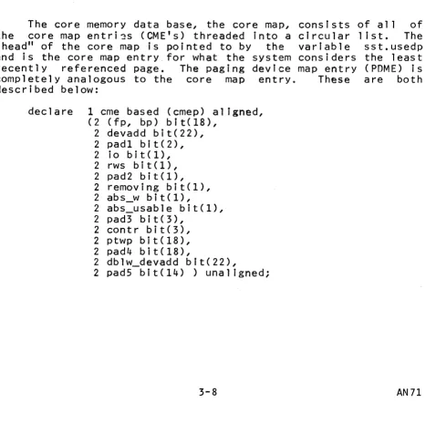
The core memory data base, the core map, consists the core map entri~s (CME's) threaded into a circular "head" of the core map is pointed to by the variable and is the core map entry_for what the system considers recently referenced page. The paging device map entry completely analogous to the core map entry. These described below:
declare 1 cme based (cmep) aligned, (2 (fp, bp) bit(l8),
2 devadd bit(22), 2 padl bit(2), 2 io bit(l), 2 rws bit(I), 2 pad2 bit(I), 2 removing bit(I),
2 abs_w bit(l),
2 abs_usable bit(I), 2 pad3 bit(3),
2 contr bit(3), 2 ptwp bit(l8), 2 pad4 bit(18),
2 dblw_devadd blt(22),
2 padS bit(14) ) unaligned;
[image:23.613.72.550.279.743.2]2 pad2 bit(l),
2 truncated bit(l),
2 notify_requested bit(l), 2 pad3 bit(l),
2 removing bit(l),
2 not_on_disk_yet bit(l), 2 pad bit(l),
2 ptV/P bit(18), 2 ht bit(18),
2 pad4 bit(36) ) unal igned;
37. cme.fp, cme.bp are the forward and backward thread
pointers used to chain the CME's
together.
38. cme.devadd
39. crne. i 0
40. crne. rv.Js
4 1. c r.l e • r e mo v i n g
42. cme. abs_'v'J
43. cme.abs_usable
44. cme.contr
is the device address associated
with the page residing in the given core block. Th i. s may be "null", a bulk store device address or a disk
device address. If it is a bulk
store device address, the disk
address can be found in pdme.devadd for the corresponding paging device map entry.
is IIO"b if the last (or pending) I/O request for the core block was a read and is "1"b if the 1 ast request was a write.
is ON only if this block of core is
being used for a read/write
sequence.
is set ON only If this block of
core is currently being deleted
from the system. If it is ON, the
core map threading algorithm does
not thread the entry into the used list, but rather leaves the entry where it is (in the remove 1 ist).
is ON only if the page residing in this block of core is abs_wired
is ON only if this block of co~e Is abs_usable.
is the controller name (processor
port number) of the controller
45. crnc.ptwp
4G. cr.le. db 1 vJ_devadd
47. pdme.fp, pdme.bp
48. pdme.devadd
49. pdme.modified
50.' pdr.le. inca r e
51. pdri1e. rV/s
52. pdme.used
53. pdme.abort
is a pointer to the PTW for the page residing in this core block or is (18)"O"b if the core block is free.
contains the secondary storage
device address to be used in the
store-through cycle of a double
write request. If this field is
(22)"O"b then no secondary write should be queued.
are the forward and backward thread pointers used to chain the POME in
the paging device used list.
Howeve r, if a read/wr i te sequence
is in progress for this paging
dev ice reco rd the PDt1 E i s .D.Q.t.
threaded into· the used list and the
pdme.bp field is used instead to
hold a pointer to the core map
entry for the block of core being used for the RWS.
contains the secondary storage
device address associated with the page residing in the corresponding "record of the paging device. This
address is never null as page
control always quarantees a disk
address has been assigned for any
pages residing on the paging
device.
is ON if the page on the paging device has been modified and hence must be written back to disk (via an RHS).
is ON if the page associated with this POME is in core.
is ON if a read/write sequence is in process for this PONE.
is ON only if the ~orresponding
paging device record is being
currently used. The record is free and available for use if this is OFF.
is ON if a process took a page
54. pdme.truncated
55. pdme.notify_requestcd
56. pdme.removing
58. pdme. ptV/P
59. pdme.ht
process of bein~ writt~n back to
~disk (t.e. an RWS was In process). This flag is tested when the RWS completes; If it is ON, the page is left on the paging device, the core used for the RWS Is ~iven to the
page, the PTW is updated to
indicate that the pa~e is in core
and the faulting process is
notIfied that this page is in core.
is ON i f a page was truncated during a RWS for thIs page.
is ON if some process wants to be notified when the RWS in progress completes.
is ON if the paging device record is currently being deconfigured.
is
on
for any (new) pages on the pag i ng dev Ice \t/h I ch have neve r been flushed to the disk. This bit isused during automatic
dcconfiguration of paging device
records to determine if the disk
copy of the page is val i d. I f the copy is not val id (has never been written) 'the disk address is freed up and the page is given a null
address. This prevents
unauthorized access of data.
points to the PTW for the page
corresponding to this POME if the segment which contains the page is
active. If the segment is not
active this field is (18)"Q"b.
is a hash thread used to thread all
POME's with the same hash index
(generated from secondary storage
59. pdme.ht is a hash threa~ used to thread all
POME's with the same hash index
(generated from secondary storage
SECTION IV
DATA BASE INITIALIZATION
This sectIon describes the inItIalIzatIon of the data bases used by the reconflguratlon software, Some of these data bases wIll not be changed after the bootload, others wIll be changed
all the time and still others will only be changed when
reconfiguration Is explicitly requested,
SCS INITIALIZATION
The system communication segment (SCS) descrIbed in Section I I I is initialized primarily by the programs scs_init, scas_init, inItialize_faults, Init_sst, start_cpu and tc_inlt. (The program
scas_init fills in scs$boot1oad_cpu_tag, which is not again
changed unless the boot1oad processor is deconfigured.)
The controller_data structure is filled in in stages as
various programs learn more about the configuration. The program
scas_init reads the system controller regIsters of each
configured controller to determIne internal interlace, etc. The processor switches are also read to determine external interlace and to verify that the actual configuration corresponds to the configuration deck.
The clock readIng mechanism consists of a pointer in
sys_Info pointing to a port addressIng word (a word wIth the high order three bIts being a port number) for the port connected to the system controller whose clock we want to use. DurIng early
addressing word are set up to point to the bootload system
controller. This function is performed first by
initial ize_faults so that the clock reading mechanism will be enabled early in the bootload. The clock reading mechanisms are
initialized uofficially" in scs_inlt.
The program scs_init initial izes many structures in SCS but
its primary concern is the initialization of the interrupt
handl ing mechanism. This includes setting up the various
interrupt mask patterns, the Interrupt handler array, and (of
importance to processor deconfigurlng) the ,variable
scs$simulate_pattern Is set up to have a bit ON for each system
interrupt the system can not afford to lose for an extended
length of time.·
SCAS INITIALIZATION
SCAS is not really a data base but rather a page table that points to pages in each of the configured system controllers. The actual content of the pages is not of importance and in general changes as pages are moved in and out of the particular region pointed to by a.glven SCAS PTW (the actual page that SCAS is set up to point to in each system controller is the first page in the controller.) As mentioned earl ier SeAS is used by the
RSCR and SSCR instructions and indeed scas init issues these
instructions as soon as SCAS is initial ized to verify the actual configuration corresponds to the configuration deck. In addition
other information about the system controllers (internal
interlace, etc.) Is saved at this time.
SST INITIALIZATION
The initial ization of the SST is
System Initialization, Order No. AN70.
features relevant to reconfiguration are:
described The two
fully in
1. the abs_usable bits In core map entries are set ON for
all core blocks In the bootload system controller (it
can't be deleted anyway because It contains maIlboxes and fault and interrupt vectors) and
2. the bulk store (paging devIce) map is initialized as
described on the "page" configuration card.
OTHER DATA BASE INITIALIZATION
The initial ization of the PRDS, done maInly by prds_init,
tc_data, tc_init and start_cpu, is straightforward and simple.
The primary interaction between the traffic controller and
SECTION V
RECONFIG AND RECONFIGURE
The processor and system controller reconfiguration software is spl it into two main programs: reconfie in the hardcore ring
and reconfigure in the user ring. These programs are so
intimately tied together that even the most trivial change to one often must be reflected sometlow in the other. They are really one logical program which has been spl it across rings for reasons
independent of the reconfiguration problem. In particular,
reconfig must be in ring zero because it performs (via calls)
privileged functions such as masking, sending interrupts and
changing hardcore·data structures. Simil~rly, reconfigure must
be in the user ring because It must perform normal terminal I/O and, of prime and nonobvious importance, it must be possible to be interrupted with a preempt interrupt from the reconfiguration
processor. This preempt interrupt (for other unrelated reasons)
cannot be allowed to go off (and be handled) in the hardcore ring.
The communication between the two programs is done through an entry in the hphcs_ gate. This entry i~ declared as follows:
declare hphcs_$reconfig entry (ptr, fixed bin, fixed bin(3S»;
call hphcs_$reconfig (rcd_ptr, entry_no, code);
3. code
is a pointer to the rcd structure described in Section II I. (Input)
is a code telling reconfig which function is being
requested. (Input)
The various "entries" into reconfir.; arc therefore implemented by one large lido case -n-" type construct where n is
the entry number. There is extensive cross checking done by
reconfig to insure that the ~roper sequence of calls is
maintained.
All processor and system controller reconfiguration is
controlled by a lock which prevents more than one process from executing a reconfiguration sequence at the same time. This lock
can be forced to the unlocked state (bypassing any sequencing
tests) via a call to the user ring program
reconfigure$force_unlock. This entry expects no arguments and
prints out the process group 10 of the last process to lock the lock.
The error code returned by reconfig is decoded by
reconfigure to determine the details of a particular error. In
particular, the code is a two-digit decimal number. The first
digit gives a general indication of what type of problem was
encountered and the second digit gives more detail. The
following tables interpret all returned error codes.
First Digit
o
1
2
7,8,9
Error Code
1 2 3 4 5 11 12 13 14 15 ,16 21 22 70 71 general
error from start_cpu error from stop_cpu general
Meaning
reconfiguration mechanism is locked reconfiguration mechanism is ll.Q.t locked
improper sequence of calls
argument is inconsistent with last call inval id entry number
processor would not start
processor has wrong CPU tag in switches wrong EIMA switch (reconfiguring
process got Initial ize interrupt itself) no APTE available for idle process
no idle process for this CPU
no processor for the given controller
no idle process for this CPU
no processor for the given controller
73 75
74 76
77 78
79
80 81
82
90 91
92
93
memory already configured
controller to be added is not defined controller cannot be removed
not enough controllers left not enough core blocks left
abs wired page in controller to be removed core block not in used 1 ist in controller
being removed
processor already configured controller not found for CPU port already assigned
illegal value for processor tag illegal value for controller illegal value for port
SECTION VI
PROCESSOR RECONFIGURATION
This section describes the workings of the processor-adding
and processor-deleting functions. Before this can be fully
described, however, the mechanism of idle processes must be
briefly explained.
IDLE PROCESSES
There is one idle process for each processor on the system. In general, the idle process for a processor is run whenever that processor cannot find another process to run, either because no other process wants service or because all processes that want service are either running on other processors or are waiting for
some system event such as a page fault to be satisfied. A
processor will never be run in another processor's idle process.
An idle proCess is a full-fledged normal Multlcs process in that it has its own stack (pds), its own descriptor segment, and
its own APT entry. In particular, an idle process can be
threaded In at the head of the eligible queue if necessary. This technique, in fact, is used to force a given processor to execute
in its idle process by Issuing a preempt interrupt to the
processor after threading the idle process APT entry to the head of the list. However, most of the time the idle processes are
threaded at the tall of the ready list where they will be
selected only if all other processors do not want to or cannot run.
The Idle process for a processor must be created before a processor is added to the system. (This Is not quite true for the bootload CPU that, of course, must somehow be bootstrapped
into the normal state. See System Initialization, Order No.
AN70, for a complete description 9f this bootstrap mechanism.)
Similarly, each processor on the system must have a processor
data segment (the PRDS) before it can be run. Both the idle
process and the PROS for a processor therefore must be created as part of the operation of dynamically addIng a processor to the system. After a processor is deleted from the system its idle process and PROS are deleted as a cleanup measure.
ADDING A PROCESSOR TO THE SYSTEM
To add a processor to the system up to four calls to
reconfig may have to be performed in additIon to the "status"
call which returns general information about the current
configuration.
The first "entry" called (number 10 or 11) communicates to
ring zero the intent to add a processor to the system. The
caller (reconfigure) mayor may not specIfy which controller the processor is to be assigned. If the caller does not specify a controller (entry number 11) the system will attempt to find one. (Recall that a controller is needed for each processor in the
system and that there must therefore be at least as many
controllers in a given configuration as processors.) At any rate a controller is selected and if the controller receives system
interrupts, the fact is noted. A processor index is then
generated and a return to the user ring is made. Note that the user ring was returned a switch indicating whether or not the new controller receives system interrupts.
The second "entry" called when adding a processor (number
15) is called to mask the controller selected above, as well as to set the channel mask in all controllers. The channel masks are set by updating all the masks in SCS and then forcing the
masks to be loaded. For controllers which get interrupts for
some CPU it Is enough to cause that CPU to take an interrupt as the interrupt interceptor will mask and hence set the channel
mask. In th is case the preempt interrupt t s sent. For
controllers which do not get interrupts an expl icit call to set their masks (to "open level") is made. Note the controller is masked to "sys_l evel" and hence all normal interrupts from
hardware devices are delayed if the controller is the system
interrupt controller. In this case any abnormal terminations of
the reconfigure request (wrong switch settings, etc.) must be
After returning from the entry which masks the new controller, the operator is instructed to change the EIMA switch
on the selected controller to the CPU being added. These
instructions (which require operator reaffirmation) are followed by the third call into ring zero (entry number 16).
This third call is the call that actually adds the processor
to the system and starts it running. The data base SCS is
changed to reflect the added CPU and the program start_cpu is called. This program creates and initial izes the PROS for the new processor as well as the new idle process. start_cpu in turn calls init_processor to get the processor going. This is done by
patch i ng the interrupt vector for a spec i al "processor
Jnitial izen Interrupt and then sending this interruPt to the new processor. The patched interrupt vector forces the new processor to enter code in init_processor which loads the OBR register of
the new idle process. After certain other initial steps the
newly added processor sets a flag saying it is successfully
running and enters the idle loop in search of a normal user
process to run. The processor which initiated the newly added
processor loops until confirmation that the new processor is
running normally. If this confirmation never comes (it waits a few mill iseconds) an error code is returned which is reflected to the reconfiguration programs.
If the processor did not add successfully (wrong switch
setting, etc.) the operator is instructed to change the EIMA
switch back and the controller is unmasked. (If the add was
successful the idle process would have unmasked). When the add is successful the initiating process resets the interrupt vector to its original state and returns control from init_processor to start_cpu to reconfig.
The program init_processor (see SYstem Initial ization, Order No. AN70) is called to start all processors on the system - even the bootload process at initial ization time. For this reason the
program makes special checks to see if it interrupted itself
(with the processor initialize Interrupt). In addition to this
check, the processor reads his configuration switches to make
sure the tag is set correctly and makes a check to see If the processor was already initial ized. (This would be the case if
the bootload processor, for example, sent the initial ize
interrupt to another processor but received it itself do to an incorrectly set EIMA switch.)
The program Inlt_processor consists of two logically
different sections. The call side is called by start_cpu when
everything has been set up for the new processor. This entry
init_processor at the label "first_steps". It Is the code at this label that first gets executed by the new processor. The code runs in absolute mode until the DBR is loaded. After the DBR is loaded the program checks its configuration as mentioned above and if all is well the program enters the "Idle" code of init_processor after sending itself a preempt interrupt. Before beginning to idle, however, the reconflguration process is told
(via a variable in init_processor) that the new process is
running. Also before idling the new processor unmasks (to
open_level) its control memory so that it can receive process
interrupts.
DELETING A PROCESSOR FROM THE SYSTEM
The first "entry" invoked when deleting a processor is
number 20. This entry checks that the CPU to be deleted is
actually in the configuration and then searches for (1) another CPU to take the illterrupts directed toward the one being deleted and (2) the first of possibly several controllers pointing to the CPU. If there is only one controller controlled by the CPU being deleted, the CPU is stopped at this time. The CPU will mask the controller when it stops (so the EIMA switch can be moved to another processor).
If there is more than one controller pointing to the CPU, one of the controllers that is nQ.t used for process interrupts is selected and its port number is returned to the user ring. For each such controller found in the system a pair of calls into ring 0 is made. The first call (number 21) is done prior to directing the operator to change the EIMA switch. It is a call to mask the controller. The second call (number 22) is performed
after the switch has been changed. It first unmasks the
controller and then searches for another controller pointing to the CPU.
The controller that gets interrupts for the CPU is done last in the sequence. In this case, instead of finding the next such controller, the CPU is actually stopped. The CPU will mask its controller prior to stopping. Entry number 23 is then invoked.
This entry waits until the CPU says it has masked and then
final step, the SCS data base is updated and the channel masks are set to reflect the absence of the processor from the system.
There are some interesting control sequences which must be followed when deleting a CPU. In particular the code which the
CPU being deleted must execute is all isolated in the idle
process and in particular in the program init_processor. In
order to force the processor to execute this code, the idle
process is given ultimate high priority (by moving to the head of the scheduler's ready list). The actual code of the idle process is a small loop consisting of: (I) code to flash the 1 ights on
the maintenance panel in a recognizable pattern, (2) some DIS
instructions to enable the panel, and (3) some tests to see if the processor is being deleted or if it should change its control
memory. The check to see if the processor should be deleted
results in the idle process invoking some code which eventually
results in the pro=essor executing a DIS. In particular, the
processor:
1. Gets the port number for its controller (used as an index into scs$controller_data).
2. Checks to see if the processor is the bootload CPU- and, if so, sends a batch of interrupts to the controller for the new bootload CPU using scs$simulate_pattern.
3. Masks the controller.
4. Checks to see if the controller for the system interrupts. If so, the CPU to get is told to change its controller and given
so it will run and see the request.
deleted then loops until the processor
controller has changed controllers.
CPU received
the controller
high priority
The CPU being to get the
Note that the deletion of the bootload CPU requires special action to be taken. This is because system interrupts (such as those that drive the disks and typewriters) are only handled by
the bootload CPU because this is the CPU which receives
interrupts from the bootload (low-order) memory and all I/O
interrupts are sent to this system controller. Since it is
necessary to mask all interrupts in an interrupt mask register whenever its EIMA switch is changed, real system interrupts must
be prevented from reaching ~ processor while this switch is
being changed (the new processor must be directed to receive
system interrupts). Since the system can not in general survive an extended period with system interrupts being processed, these interrupts must be simulated by sending every interrupt which may
be of interest to the processor which is to receive system
interrupts. These interrupts are remembered In the
scs$simulate_pattern cell at initial ization time, and broadcast
to the ~ bootload CPU every second or so by the CPU being
deleted.
Another item to be noted is that the several places In the
reconfigura~ion software where masks are set in controllers are
bracketed QY calls to force the running (rcconfiguring) process
to run on a particular processor the processor which is
control for the system controller whose mask is being changed. The "processor required" mechanism built into the dispatcher of the traffic controller is used for this purpose. Therefore, if reconfiguration is attempted from a process already restricted to a given processor, that restriction may not be in effect after the reconfiguration is complete. (The "processor required" mechanism does not "stack" requests.)
Since adding a processor to the system requires the operator (see Section IX) to interact at his terminal, it is not possible to add a processor to the system automatically. This means that it is not possible to bootload the system and have it come up
with two processors running. The second and subsequent
SECTION VII
MEMORY RECONFIGURATION
This section describes the mechanisms used to dynamically
reconfigure primary memory (core or MaS). The first two
subsections describe system controller reconfiguration and the
third subsection describes the core block reconfiguration within a controller.
ADplNG A SYSTEM CONTROLLER TO THE SYSTEM
At system initial ization time the data bases
scs$controller_data and the main memory map in the SST are
initialized. These are initial ized from the configuration deck
(and active register values); since the core map can not easily be grown it is required that any system controllers that will ever be configured to the system for a given bootload must be
specified in the configuration deck for the bootload. This is
done by using an ON or OFF field of the MEM configuration cards.
All system controllers actually configured and to be used at
bootload time are indicated as being ON. Other system
controllers are OFF.
When the core map ,is Initially set up, only core blocks which are In configured system controllers are threaded into the used 1 ist. Core blocks for system controllers that are not yet configured are left 'alone and threaded into no 1 ist. To add a system controller (and :its memory) to the system, all that need be done is to thread the (hopefully unused) core blocks for the
controller into the core-used list. This is exactly what
particular the EIMA switch is set to the processor that controls
the system controller. Note that the entire system can be
prepared (I.e., all switches set correctly) before the addmem
request Is given by the operator.
The actual code in reconflg to add a system controller to the system, entry 30, merely checks consistency of all arguments and calls add_memory to actually add the system controller to the system. The program add_memory first sets the Interrupt mask in
the memory -- to load the appropriate channel mask and then
threads the core map entries for core blocks in the controller into the used list. Before call ing add_memory, reconfig forces the executing proc~ss to run on the processor that controls the memory so the mask can be set.
REMOVING A SYSTEM CONTROLLER FROM THE SYST~
The mechanis~ to remove a system controller from the system
is compl icated by two features. First, a mechanism must be
provided to remove all references to any pages in the system controller by processors. Second, a mechanism must be provided to remove all references to the memory of the system controller by other active modules, particularly 10M's.
The first major problem in removing main memory, i.e.,
preventing processors from referencing the memory, is not hard to solve in that all processor references to the memory are indirect through PTW's over which the system software has control. (It is
not possible to remove a system controller that contains
permanently wired code or data.) It is thus necessary only to remove access in PTW's or copy pages into core that is not being removed. This in fact is just what is done. There are three cases to £onsider:
1. Core blocks that contain wired pages.
2. Core blocks that contain pages that are not wired but are modified.
3. Other core blocks.
the i r assoc i at i ve memor t es so that they will refetch the PTW wi th the new address and make all subsequent references to the copy. If the page is modified whrle the copy is being performed, all processors are stopped (forced to loop, via a connect fault) and the copy is made while no one can modIfy the data. The entire
mechanism to move a wired page Is Implemented tn the program
evict_page.
Pages that are modified are simply written out and evicted when the I/O completes. ThIs process continues until a page does not get modified while the I/O is going on In which case the block of memory can be claimed.
Pages that are neither wired nor modified are evicted
immediatelY (the PTW is set to fault) unless I/O is in progress, in which case the I/O is waited for and the block is claimed on the next pass.
The program (pc_abs$remove_core) that does all this work
loops through all blocks in the given controller until a pass is completed that leaves no blocks unclaimed.
The second major problem in removing main memory, that of preventing other active modules from referencing the memory, is
solved before it even becomes a problem. This is via the
abs_wiring technique, which requires that ~ pages that are
referenceable via nonprocessor active modules (e.g., the 10M)
cannot reside in a deconfigurable system controller. In order to do this, certain controllers are set up as "abs_usable" and hence
nondeconfigurable. For most configurations, the bootload memory
alone is abs_usable, but the system dynamically chooses other
controllers as necessary if there is not enough abs_wireable
memory in the bootload controller.
Therefore any program that uses a page for I/O (that is not permanently wired) must call a special program to have the page wired down. This program is pc_contig. See The Storage System, Order No. AN61, for a complete description of this mechanism. The dynamic deconfiguration software need not be concerned about
pages wired for I/O activity.
When a system controller is deleted from the system, a check
must be made to see' if the system controller is used by a
processor as its process interrupt controller. If this is the
case, another controll~r must be found for the processor that in turn may require the changing of the EIMA switch on the newly selected controller if it is controlled by a CPU other than the
one losing its interrup~ controller. All of these cases are
will take several calls into the hardcore ring to: (1) communicate with the operator via the typewriter, and (2) mask
and unmask as the EIMA switch Is changed. The variable
scs$change_contr is analogous to the varIable scs$delete_cDu and is sampled by the idle process (that is given prIority so It will run) in its normal idle loop. If the change_contr flag is set, the program init_processor will perform the necessary changes (In the correct PROS) to reflect the change. It wIll also signal
when it is done by resetting the flag. The program
stop_cpu$switch_contr is used to InItiate this mechanIsm.
AUTOMATIC MEMORY DELETION
To be supplied.
SECT I ON V I I I
BULK STORE RECONFIGURATION
The bulk store reconftguration mechanisms differ from the
system controller mechanisms in that records of the bulk store are reconfigured rather than the active module, the bulk store controller, being reconfigured. However, the software is set up so that If ~ records on a given bulk store are removed from
active use by the system, the controller can safely be
deconfigured for offl ine test or for use by another local system.
No switches need be changed during this reconftguration
mechanism. (It is, of course, necessary that any parts of the bulk store that are to be used by a system be configured to that
system the bulk store reconfiguration software assumes that
necessary configuration switches have been set and does not
remind the operator about these switches.>
During system initial ization (see System Initialization,
Order No. AN70> the "page" configuration card is read to determine which bulk store records are to be initially used by the system. The paging device map is read in; if it has not been successfully cleaned up, the system is crashed. Otherwise, there is no val id data on the bulk store and all records that are to be used have the paging device map entries (PDME's> threaded into
the paging device used list and marked as free. Until
reconfiguration time all of these records wIll remain in this
used list unless:
1. The record is removed for a moment as part of a
rethreading operation,
2. The record is removed because a read/write sequence is in progress for the given page, or
The paging device map (1 ike the core map) can be searched either by following the used list thread or by indexing into the map with a given record number. The latter method Is used for bulk store reconfiguration under operator control.
The main supervisor program that controls bulk store record reconfiguration is delete_pd_records. This program, callable through the hphcs_ gate, has two entries as described below:
declare delete_pd_records entry (fixed bin, fixed bin, fixed bin(3S»;
call delete_pd_records (first, count, code);
1. fi rst
2. count
3. code
is the record number of the first of count contiguous records to be removed from active use by the system. (Input)
is the number of records being deconfigured. ( I npu t)
indicates, if nonzero, that the input parameters were inconsistent with the current configuration. (Output)
declare delete_pd_records$add_pd_records entry (fixed bin, fixed bin, fixed bin(3S»;
1. - 3. are analogous to above.