ISSN Online: 2161-7589 ISSN Print: 2161-7570
Assessment Slope Stability Based on Deformation
of Rock Joints and Soil with Simulation Method
Mohsen Damani Gol
1, Hamed A. Keykha
2*, Jafar Rahnama-Rad
11Department of Geology, Zahedan Branch, Islamic Azad University, Zahedan, Iran 2Department of Civil Engineering, Buein Zahra Technical University, Buein Zahra, Iran
Abstract
The study of slope stability was measured around areas. The first area is rock insta-bility in conglomerates walls, and the second area is soil instainsta-bility in a slope com-posed of sand gravel and shale in the south of the study area. In the first area, rock slopes were studied by fractures condition, slope morphology, measured engineering features of rocks, and then interpreted by Dips software to define the fracture types for analysis of block toppling. The rock slope of the area was modeled by Rock plan by adding water penetration and earthquake. The results showed that in dry condi-tion these slopes were stable, but by penetrating water and saturacondi-tion of the open spaces of the fractures, the block toppling will occur. Also, seismic activities in the area caused the instability of the slopes, and landslide will happen. In the second area, landslides were spoon-shaped type. To investigate the soil slope stability, the condition of slope was modeled by using soil engineering properties and measuring the morphological condition of the slope such as slope dip, layers thickness, layers dip and slope elevation. It was shown instability of the soil slopes. To stabilize the sliding areas, the dip changing method and formation of stepped-style slope were done. However, the new condition changed the formation of sliding areas in the up-per most part of the stairs. The retaining walls formed from the local materials were applied to the slope to provide the desire stability.
Keywords
Soil Instability, Kinematic Studies, Top Ling, Rock Plan
1. Introduction
Today, fast developments in civil projects due to the fast population growth as well as providing the human needs, development of cities, and villages, and their development
How to cite this paper: Gol, M.D., Keykha, H.A. and Rahnama-Rad, J. (2016) Assess-ment Slope Stability Based on Deformation of Rock Joints and Soil with Simulation Method. Open Journal of Geology, 6, 983- 995.
http://dx.doi.org/10.4236/ojg.2016.69074
Received: July 22, 2016 Accepted: August 30, 2016 Published: September 2, 2016
Copyright © 2016 by authors and Scientific Research Publishing Inc. This work is licensed under the Creative Commons Attribution International License (CC BY 4.0).
toward the slope areas, placement of transportation roots such as roads and railroads, and focused structures such as cities and villages, occurrence of landslides and conse-quent hazards are highly considered. Unfortunately, due to lack of attention to slope stability in the civil projects, every year especially after heavy precipitations and earth-quakes, catastrophic happenings related to slope instability, in particular rock fall are observed in Iran. Since Iran has a lot of mountainous areas, the road construction projects face with passing through the mountains, which necessitates the stability stu-dies in terms of natural and man-made slopes to ensure successful achievement and safety of the projects. A voluminous number of studies have been done related to slope stability including rock block and soil analysis [1]-[8]. Landslide occurs in mountain-ous areas of Iran every year, which results in significant damages. There are no accurate statistical data and related damages of landslides in Iran. Although no damage survey-ing has been done yet, the hazards both direct and indirect ones, occur highly every year, including destruction of residential areas, roads, farmlands, gardens, jungles, soil erosion and production of sediments.
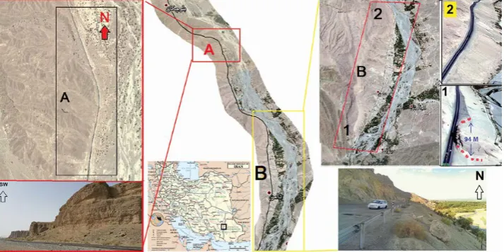
2. Study Area
The study area is situated in Baluchestan province, which is located in the south east of Iran, between Khash and Iran shah cities: N60047, E27˚36 (area A) and N27˚26, E27, 26 (Area B), as shown in Figure 1.
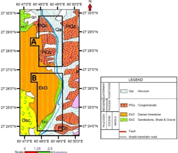
3. General Geology
[image:2.595.197.554.511.689.2]The study area belongs to Makran and East Iran zone (Nahbandan-Khash zone) based on the Iran’s structural classification [9]. Stöcklin [9] has interpreted this area as sepa-rated zone from Zagros zone along with Oman uplift, which is the continuous part of Baluchestan and India. Camp and Griffis [10] believed that occurrence of rifting in Middle Cretaceous, the Lut zone is separated from Afgan Block and an oceanic basin occurred in which flysch sediments are deposited. Bagheri [11] said that Sistan suture
zone in east south of Iran, called flysch belt occurred post Cretaceous, which joins to Makran zone in east south of Iran. Flysch is deposited on the Upper Cretaceous ophi-olites and related higher pressure metamorphic rocks, similar to accretionary wedges sequences. Based on the stratigraphic studies of Iranshahr map (1:250,000), there is no evidence of existence of older units prior to Cretaceous. The youngest sediments be-longed to Quaternary and the oldest sediments occurred in the Middle Eocene.
Khash-Iranshahr road in area a passes from the column of sediments with 13 m thickness composed of conglomerate of Eocene (PLQC). In this area large scale rock slides are seen sometimes having over 10 m in dimension. In area B, the road is located on soil slopes, composed of sand gravel, shale and sandstone (EK2) (Figure 2).
4. Methodology
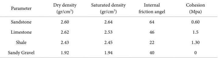
[image:3.595.193.553.377.686.2]Based on the field studies, the potential unstable slopes including rock and soil slopes were defined. Slope morphology, discontinuity features such as dip and strike direction as well as groundwater condition were investigated. The soil and rock sampling were done to define the engineering properties of the components. The lab work were con-ducted and the engineering properties of soil and rock samples, including especial weight, saturated especial weight, cohesion, angle of internal friction, and grain size were determined (Table 1).
Table 1. The Geomechanic features of rock and soil materials in study area.
Parameter Dry density (gr/cm3) Saturated density (gr/cm3) friction angel Internal Cohesion (Mpa)
Sandstone 2.60 2.64 64 0.60
Limestone 2.62 2.53 46 1.5
Shale 2.43 2.45 22 1.30
Sandy Gravel 1.92 1.94 40 0
In this study, to measure and interpret the rock slope stability, at first, geometric of slope dip, elevation of dip, especial weight, and angle of internal friction were entered to Rock plane software. In this analysis, the slope stability was investigated in dry con-dition. Then, after importing the groundwater condition, the rock slope stability was interpreted and safety factor for every condition was considered. The analysis of the soil slopes was done via shear method, by which slope was divided to several sections and force conditions for every section was calculated. According to the effect of forces, sev-eral methods can be used, among them; simplified Bishop Method can provide a more realistic safety factor. The analysis points investigated in this study are included the slope dip condition, soil layering, and engineering properties of soil such as cohesion, especial weight, saturated especial weight, angle of internal friction, and survey soil slope stability.
5. Results and Discussion
5.1. Area A, Rock Slope
5.1.1. Fractures Conditions and Failures Analysis
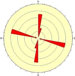
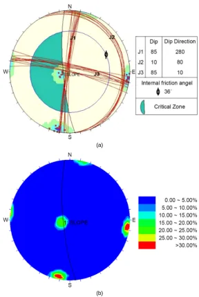
In this area, three groups of fractures are recognized, consisting near horizontal frac-tures and the other two groups are perpendicular to each other, which created large blocks of rocks. These fractures were measured (Figure 3).
The measured fractures have been interpreted stereographically, showing that the majority of the fractures place in three main groups, one of them near horizontal frac-tures and two others are perpendicular to each other; making large rock blocks (Figure 4).
The failures analysis of the area was done by analyzing the morphological properties of the slope such as slope dip and strike, failures dip and strike, applying the angle of internal friction, using Dips program. It showed that the failures are block toppling type. Other conclusions are:
• 32% of fractures that are almost horizontal belong to critical zone, which cause the block toppling.
• 35% of fractures are developed in N-S strike.
• 33% of fractures are developed in near E-W strike (Figure 5).
5.1.2. Rock Slope Stability of Area A under Dry and Saturated Conditions
Figure 3. Measurement of joints in the study area.
[image:5.595.247.498.434.687.2](a)
[image:6.595.228.517.65.495.2](b)
Figure 5. Fractures location of the study area.
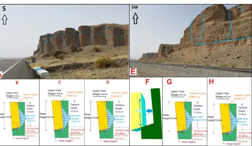
and the stability level was measured. To do so, the block landslide model was created by applying failures of the area and the engineering properties of the rocks such as cohe-sion and angle of internal friction and then the safety factor was calculated (Figure 6). Fractures in this study area play a role as water channels and lead the precipitations to different part of this block. So, the slope condition was modeled under penetration of water condition to the fractures. The percentage of filling of the slope was interpreted and the safety factor was calculated (Figure 7).
Since the safety factor of stable and unstable boundary of a slope is 1.5, the condi-tions presented herein display the stability condition passing the critical line. Also, conditions in which 100% of the failure space is filled is studied, which can provide the worst condition, resulting in preventive solutions.
Figure 6. Wall condition under penetration of water. A = Area 1; B = When 100% of fractures spaces is filled by water; C = When 79% of fractures spaces is filled by water; D = When 80% of fractures spaces is filled by water; E = Area 2; F = When 100% of fractures spaces is filled by water; G = When 79% of fractures spaces is filled by water; H = When 80% of fractures spaces is filled by water.
Figure 7. Filling percentage of failures spaces and the safety factor.
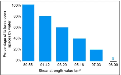
1) The stability behavior of the block is different when water is added and the failures spaces are filled. This behavior depends on the percentage of the filled open spaces and by increasing the water penetration to the slope, the shear strength of slope decrease, which decrease the safety factor (Figure 8).
[image:7.595.193.551.414.582.2]Figure 8. Effect of water penetration on shear strength.
3) When 80% of the fractured slope is filled by water, the slope stability index is 1.49, which is the yielding point of starting instability in the block, causing the block top-pling.
4) Eventually, if 100% of the fractured spaces is filled by water, the slope stability in-dex becomes 1.18 and cause the landslide.
5.1.3. Stability Condition under Seismic Phase
In this part, the stability condition and safety factor is acquired by applying seismic in-dex in the model. According to the seismic studies of crust in Iran, based on the stan-dard of bylaw 2800 and based on the same acceleration seismic hazard zoning map of the study area in 75 year back period is defined, having maximum probable earthquake of 0.30. So, the aforementioned seismic acceleration is added to the slope and its stabil-ity in the seismic condition is calculated. Table 2 shows the slope stability condition in different situations. According to the slope stability, safety factor presented by US as 1.5, the results of this study are presented in Table 2.
5.2. Interpretation of Soil Slope Stability in Area B
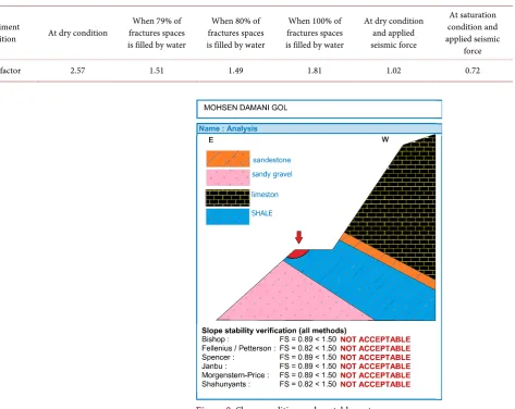
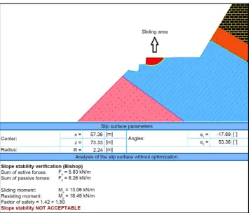
After defining the engineering properties and morphological properties, slope dip of mentioned slope was modeled and the slope stability was interpreted. Based on the re-sults, a part of dip of the slope shows safety factor of 0.89, displaying the unstable con-dition and potential to slide occurrence (Figure 9).
5.2.1. Strategies of the Stabilizing of Slope 1) Changing the dip and elevation
Table 2. Results of slope stability in different situations.
Experiment
condition At dry condition
When 79% of fractures spaces is filled by water
When 80% of fractures spaces is filled by water
When 100% of fractures spaces is filled by water
At dry condition and applied seismic force At saturation condition and applied seismic force
[image:9.595.80.554.84.460.2]Safety factor 2.57 1.51 1.49 1.81 1.02 0.72
Figure 9. Slope condition and unstable part.
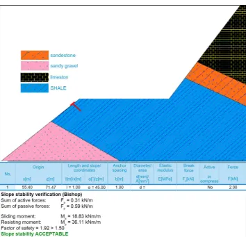
If the dip and elevation changes applied on the soil slope stabilization, this slope will be stabilized, but these changes will form a slope with new morphology, causing forma-tion of new sliding areas (Figure 5) and the safety factor of the new slope condition becomes 1.42 which shows the slope slide potential (Figure 11).
2) Stabilizing by construction of retaining wall
One of the other common methods of landslide hazards are retaining walls typically place in a vertical manner. To construct these walls, the vertical soil digging of the po-tential sliding is necessary. Figure 12 shows the modeled of sliding slope and then re-taining wall is builds up by using the local materials (limestone blocks). By applying the retaining wall, the slope safety factor becomes 11.5 and the slope in this condition is completely stable (Figure 12).
3) Slope stabilizing by anchor construction
Figure 10. Slope stabilizing by changing of dip and elevation.
[image:10.595.195.554.382.686.2]Figure 12. Slope condition by applying retaining wall.
[image:11.595.195.550.345.686.2]6. Conclusions
The existing faults in this slope act as the water channel and pass the precipitations to different part of this block. By increasing the amount of water penetration, the shear strength decreases, and therefore the slope safety factor decreases. According to the studies, if over 79% of the fracture spaces fill out with water, the slope will be unstable and landslide will occur. The slope instability to seismic activities shows that activating the seismic phase results in slope instability due to presence of fracture group perpen-dicular to each other, causing the slope slide in block sliding manner.
In area B, soil slope is 2 km in length and a road is constructed on. The slope stability investigation of this slope shows soil slide in this area. By changing the dip and stepped- style strategy, the slope stability was achieved. However, the new condition forms new morphology for the slope, causing spoon-like slide in the upper most part of the stair part. To solve this issue, the retaining walls were applied, which were formed by local material to ensure the slope stability. Also, the anchor approach can be used to stabilize the soil slope.
References
[1] Baba, K., Bahi, L., Ouadif, L. and Akhssas, A. (2012) Slope Stability Evaluations by Limit Equilibrium and Finite Element Methods Applied to a Railway in the Moroccan Rif. Open Journal of Civil Engineering, 2, 27. http://dx.doi.org/10.4236/ojce.2012.21005
[2] Fall, M., Azzam, R. and Noubactep, C. (2006) A Multi-Method Approach to Study the Sta-bility of Natural Slopes and Landslide SusceptiSta-bility Mapping. Engineering Geology, 82, 241-263. http://dx.doi.org/10.1016/j.enggeo.2005.11.007
[3] Guariguata, M.R. (1990) Landside Disturbance and Forest Regeneration in the Upper Lu-quillo Mountains of Puerto Rico. Journal of Ecology, 78, 814-832.
http://dx.doi.org/10.2307/2260901
[4] Hussain, G., Singh, Y. and Bhat, G.M. (2015) Geotechnical Investigation of Slopes along the National Highway (NH-1D) from Kargil to Leh, Jammu and Kashmir (India). Geomaterials, 5, 56. http://dx.doi.org/10.4236/gm.2015.52006
[5] Keykha, H.A., Zainuddin, B.M.Y. and Ali, T.A.M. (2011) Kinematic Analysis of Blocks in Tunnel on the Basis of Discontinuities. Electronic Journal of Geotechnical Engineering, 16, 513-520.
[6] Latha, G.M. and Garaga, A. (2010) Seismic Stability Analysis of a Himalayan Rock Slope.
Rock Mechanics and Rock Engineering, 43, 831-843. http://dx.doi.org/10.1007/s00603-010-0088-3
[7] Liu, Y. and Geo, F. (2015) Dynamic Stability Analysis on a Slope Supported by Anchor Bolts and Piles. Electronic Journal of Geotechnical Engineering, 20, 1887-1900.
[8] Wu, Y.F. and Wang, Z.G. (2014) Stability Analysis of Unsaturated Swelling Soil Slope with Double Strength Reduction Method. Electronic Journal of Geotechnical Engineering, 19, 8965-8975.
[9] Stocklin, J. (1968) Structural History of Iran Review. Bulletin: American Association of Pe-troleum Geologists, 52.
[11]Bagheri, S. and Stampfli, G.M. (2008) The Anarak, Jandaq and Posht-e-Badam Metamor-phic Complexes in Central Iran: New Geological Data, Relationships and Tectonic Implica-tions. Tectonophysics, 451, 123-155. http://dx.doi.org/10.1016/j.tecto.2007.11.047
Submit or recommend next manuscript to SCIRP and we will provide best service for you:
Accepting pre-submission inquiries through Email, Facebook, LinkedIn, Twitter, etc. A wide selection of journals (inclusive of 9 subjects, more than 200 journals)
Providing 24-hour high-quality service User-friendly online submission system Fair and swift peer-review system
Efficient typesetting and proofreading procedure
Display of the result of downloads and visits, as well as the number of cited articles Maximum dissemination of your research work