Technology (IJRASET)
Modular Cascaded Multilevel PV Inverter Using
Distributed MPPT By ANFIS Controller For
Grid-Connected Applications
M.Sambasiva1, Mr.C.S.Ravichandran M.E.(Ph D)2
1
M.TECH Student, 2Associate Professor Dep. of EEE SVCET, Chittoor, Andhrapradesh, India
Abstract: This paper shows a modular cascaded H-bridge multilevel photovoltaic (PV) inverter for single-or three-stage grid associated applications. The modular cascaded multilevel topology enhances the effectiveness and adaptability of PV systems. To acknowledge better usage of PV modules and boost the solar energy extraction, an appropriated maximum power point tracking control plan is connected to both single-and three-stage multilevel inverters, which permits autonomous control of each dc-link voltage. For three-stage grid associated applications, PV mismatches may present unequal supplied power, driving to unequal grid current. To comprehend this issue, a control plan with modulation compensation scheme is likewise proposed. An exploratory three-stage seven-level cascaded H-bridge inverter has been manufactured using nine H-bridge modules (three modules for each stage). Each H-bridge module is associated with a 185-W solar panel. Simulation and, experimental results are introduced to confirm the practicality of the proposed approach.
I. INTRODUCTION
Because of the lack of fossil fuels and natural causes created by ordinary power era, renewable energy, especially sun oriented energy, has turned out to be extremely well known. Solar electric-energy demand has become reliably by 20%–25% for each annum in the course of recent years, and the development is for the most part in system associated applications. With the exceptional market development in grid associated photovoltaic (PV) systems, there are expanding interests in grid associated PV arrangements.
Five inverter families can be characterized, which are identified with distinctive arrangements of the PV system: 1) central inverters; 2) string inverters; 3) multi string inverters; 4) ac module inverters; also, 5) cascaded inverters. The arrangements of PV systems are appeared in Fig. 1.
Technology (IJRASET)
Fig.1. Configurations of PV systems. (a) Central inverter. (b) String inverter.(c) Multi string inverter. (d) AC-module inverter. (e) Cascaded dc/dc converter. (f) Cascaded dc/ac inverter.
A measured cascaded H-bridge multilevel inverter topology for single-or three-stage grid associated PV systems is exhibited in this paper. The panel mismatches issues are tended to demonstrate the need of individual MPPT control, and a control plan with circulated MPPT control is then proposed. The distributed MPPT control plan can be connected to both single and three-stage systems. What's more, for the introduced three-stage grid associated PV system, if each PV module is worked at its own particular MPP, PV mismatchs may acquaint unequal power supplied with the three-stage multilevel inverter, prompting unequal infused grid current. To adjust the three-stage grid current, modulation compensation is additionally added to the control system.
II. SYSTEM DESCRIPTION
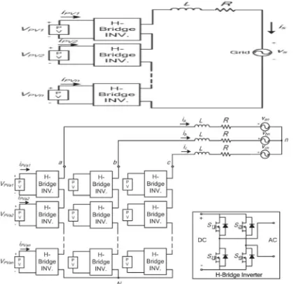
Modular cascaded H-bridge multilevel inverters for single and three-stage grid associated PV systems are appeared in Fig. 2. Every stage comprises of n H-bridge converters associated in arrangement, and the dc connection of every H-bridge can be fed by a PV panel or a short string of PV panels. The cascaded multilevel inverter is associated with the grid through L channels, which are used to decrease the exchanging music in the current. By various mixes of the four switches in each H-bridge module, three output
voltage levels can be created: −vdc, 0, or +vdc. A cascaded multilevel inverter with n information sources will give 2n + 1 levels to
orchestrate the air conditioner output waveform. This (2n + 1) - level voltage waveform empowers the diminishment of sounds in the incorporated current, lessening the measure of the required output channels. Multilevel inverters too have different points of interest, for example, diminished voltage weights on the semiconductor switches and having higher productivity when contrasted with other converter topologies.
III. PANEL MISMATCHES
Technology (IJRASET)
required to expand the productivity of the PV system.
[image:4.612.201.411.92.295.2]Fig. 2. Topology of the modular cascaded H-bridge multilevel inverter for grid-connected PV systems.
Fig. 3. Power extracted from two PV panels.
Fig. 4. P–V characteristic under the different irradiance.
To tackle the PV mismatch issue, a control plan with individual MPPT control and balance pay is proposed. The points of interest of the control plan will be examined in the tracking segment.
IV. CONTROL SCHEME
A. Distributed MPPT Control
Keeping in mind the end goal to dispose of the antagonistic impact of the befuddles and expand the productivity of the PV system, the PV modules need to work at various voltages to enhance the usage per PV module. The different dc links in the cascaded H-bridge multilevel inverter make free voltage control conceivable. To figure it out individual MPPT control in each PV module, the control plan proposed in [19] is redesigned for this application. The circulated MPPT control of the three-stage cascaded H-bridge inverter is appeared in Fig. 5. In every H-bridge module, a MPPT controller is added to create the dc-link voltage reference. Every dc-link voltage is contrasted with the comparing voltage reference, and the whole of all mistakes is controlled through an aggregate
voltage controller that decides the current reference Idref . The receptive current reference Iqref can be set to zero, or if receptive
[image:4.612.196.414.318.504.2]Technology (IJRASET)
controllers to produce the adjustment record in the dq facilitates, which is then changed over back to three stages.
The disseminated MPPT control plan for the single-stage system is about the same. The aggregate voltage controller gives the greatness of the dynamic current reference, and a PLL gives the recurrence and stage point of the dynamic current reference. The present circle then gives the tweak list. To make each PV module work at its own MPP, take stage an as a case; the voltages vdca2
to vdcan are controlled exclusively through n − 1 circles. Every voltage controller gives the regulation record extent of one H-bridge
module in stage a. After increased by the regulation record of stage a, n − 1 regulation records can be gotten. Additionally, the
regulation record for the primary H-bridge can be acquired by subtraction. The control plans in stages b also, c is just about the same. The main distinction is that all dc-link voltages are directed through PI controllers, and n adjustment record extents are acquired for every stage.
Fig. 5. Control scheme for three-phase modular cascaded H-bridge multilevel PV inverter.
A phase-shifted sinusoidal pulse width modulation switching scheme is then connected to control the switching devices of each H-bridge. The incremental conductance technique has been utilized in this paper. It lends itself well to computerized control, which can effectively monitor past estimations of voltage and current and settle on all choices.
B. Modulation Compensation
As specified before, a PV mismatch may bring about additional problems to a three-stage modular cascaded H-bridge multilevel PV inverter. With the individual MPPT control in each H-bridge module, the info solar power of every stage would be distinctive, which acquaints uneven current with the grid. To tackle the issue, a zero sequence voltage can be powered upon the stage legs so as to influence the present streaming into each stage. In the event that the redesigned inverter output stage voltage is corresponding to the uneven power, the present will be adjusted. In this manner, the modulation compensation block, as appeared in Fig. 6, is added to the control arrangement of three-stage modular cascaded multilevel PV inverters. The key is the manner by which to overhaul the balance record of every stage without expanding the complexity of the control system. To start with, the unequal power is weighted by proportion rj,
Technology (IJRASET)
Where Pinj is the info power of stage (j = a, b, c), and Pinav is the normal info power. At that point, the infused zero arrangement
adjustment file can be produced as
Where dj is the adjustment record of stage (j = a, b, c) and is dictated by the present circle controller. The adjustment record of every
stage is redesigned by
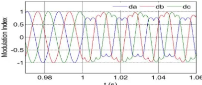
Just straightforward estimations are required in the plan, which won't build the many-sided quality of the control system. A case is displayed to demonstrate the adjustment remuneration plot all the more unmistakably. Expect that the information power of each stage is unequal
By infusing a zero succession tweak list at t = 1 s, the adjusted tweak file will be redesigned, as appeared in Fig. 7. It can be seen that, with the remuneration, the overhauled balance record is uneven relative to the power, which implies that the output voltage
[image:6.612.212.415.406.492.2](vjN) of the three-stage inverter is uneven; however this creates the sought adjusted grid current.
Fig. 7. Modulation indices before and after modulation compensation.
V. SIMULATION RESULTS
To confirm the proposed control plot, the three-stage grid connected PV inverter is mimicked in two distinctive conditions. In the
first place, all PV panels are worked under the same irradiance S = 1000 W/m2 and temperature T = 25 ◦C. At t = 0.8 s, the sun
powered irradiance on the first and second panels of stage a declines to 600 W/m2, and that for alternate panels sticks with it same. The dc-link voltages of stage are appeared in Fig. 8. At the starting, all PV panels are worked at a MPP voltage of 36.4 V. As the irradiance changes, the first and second dc- link voltages abatement and track the new MPP voltage of 36 V, while the third panel is still worked at 36.4 V.
Technology (IJRASET)
[image:7.612.206.423.85.177.2]DC-link voltage of module 3.
Fig. 8. DC-link voltages of phase a with distributed MPPT (T = 25 .C).
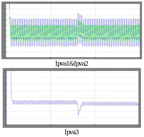
The PV current waveforms of phase are
Ipva1&Ipva2
[image:7.612.189.425.214.438.2]Ipva3
Fig. 9. PV currents of phase a with distributed MPPT (T = 25 .C).
[image:7.612.203.411.527.610.2]The dc-link voltages of stage b are appeared in Fig. 10. All stage b panels track the MPP voltage of 36.4 V, which appears that they are not affected by other phases. With the conveyed MPPT control, the dc-link voltage of every H-bridge can be controlled freely. At the end of the day, the associated PV panel of every H-bridge can be worked at its own particular MPP voltage also, won't be impacted by the panels associated with other H-bridges. In this way, more solar energy can be extricated, and the effectiveness of the general PV system will be expanded.
Technology (IJRASET)
Phase A
Phase B
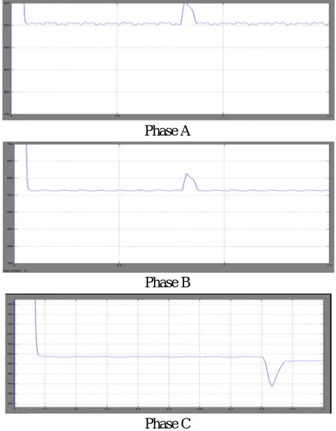
[image:8.612.186.427.77.386.2]Phase C
Fig.11. Power extracted from PV panels with distributed MPPT
Be that as it may, by applying the modulation compensation, the power infused to the grid is still adjusted, as appeared in Fig. 12. It can be seen that there is no additional power misfortune brought on by the modulation compensation scheme plan.
Fig. 12. Power injected to the grid with modulation compensation.
Fig. 13 shows the output voltages (vjN) of the three-phase inverter. Due to the injected zero sequence component, they are
[image:8.612.195.417.457.548.2]unbalanced after t = 0.8 s, which help to balance the grid current shown in Fig. 14.
[image:8.612.199.414.606.686.2]Technology (IJRASET)
Fig. 14. Three-phase inverter output voltage waveforms with modulation compensation.
Proposed model voltage and current THD values
Load voltage THD 20.50%
Load current THD 1.15%
VI. EXTENSION RESULTS
In our proposed method PI controller is used. To get a better performance we used ANFIS controller instead of PI controller. Advantages of ANFIS Controller over PI Controller: Implementation of traditional control "PI", its response is not so good for non-linear systems. The improvement is remarkable when controls with ANFIS logic are used, obtaining a better dynamic response from the system. The PI controller requires precise linear mathematical models, which are difficult to obtain and may not give satisfactory performance under parameter variations, load disturbances, etc. Recently, ANFIS Controllers (ANFIS Cs) have been introduced in various applications and have been used in the power electronics field. The advantages of ANFIS controllers over conventional PI controllers are that they do not need an accurate mathematical model, Can work with imprecise inputs and Can handle non-linearity and are more robust than conventional PI controllers.
Load voltage THD 16.77%
Load current THD 0.57%
VII. CONCLUSION
From the above results we can conclude that the multilevel inverter topology will enhance the use of associated PV modules if the voltages of the different dc connections are controlled autonomously. a conveyed MPPT control plan has been connected to build the general effectiveness of PV systems. An adjustment pay plan, which won't build the intricacy of the control system or cause additional power misfortune, is added to adjust the grid current even with the uneven supplied sun powered power. And finally by observing the THD values this system gives better performance when ANFIS controller was used.
REFERENCES
[1] J. M. Carrasco et al., “Power-electronic systems for the grid integration of renewable energy sources: A survey,” IEEE Trans. Ind. Electron., vol. 53, no. 4, pp. 1002–1016, Jun. 2006.
[2] S. B. Kjaer, J. K. Pedersen, and F. Blaabjerg, “A review of single-phase grid connected inverters for photovoltaic modules,” IEEE Trans. Ind. Appl., vol. 41, no. 5, pp. 1292–1306, Sep./Oct. 2005.
[3] M. Meinhardt and G. Cramer, “Past, present and future of grid connected photovoltaic- and hybrid power-systems,” in Proc. IEEE PES Summer Meet., 2000, vol. 2, pp. 1283–1288.