Technology (IJRASET)
©IJRASET: All Rights are Reserved
711
Farmer Alert System
Mayur Naik1, Raj Kolvenkar2, Shruti Mardolkar3
1234
Dept. of Electronic and Telecommunication, Don Bosco College Of Engineering, Fatorda, Goa, India
Abstract--The rapidly advancing mobile communication technology and the decrease in costs make it possible to incorporate mobile technology into home. This paper is on “FARMER ALERT SYSTEM” which gives an elaborate view and understanding of the design and functioning. This paper reviews the problems the farmer have to face regarding the manual turning on and off of motors and tries to solve them by remotely turning On and Off of the Irrigation motors. This tries to solve some disadvantages the previous existing systems had in it.
Keywords: Android, GSM module, MCB, microcontroller, regulated power supply, SMS.
I. INTRODUCTION
In today’s fast changing world, everything is becoming compact, portable and mobile. The mobile handsets for communication are the biggest advancement in the area. These have made our lives much simpler and connected. Today almost everyone is familiar with it’s usage, and is able to draw advantage from it. GSM digitizes and compresses data, then sends it down a channel with other streams of user data, each in its own time slot. It operates at either the 900 MHz or 1800 MHz frequency band.
GSM provides with Subscribers Identity Module (SIM) to every user. It is a detachable card which identifies user’s account to the network and provides authentication, that allows appropriate billing. The unique roaming features of GSM allow cellular subscribers to use their services in any GSM service area in the world in which their provider has a roaming agreement. The idea behind the project is to utilize the mobile nature of communication and application provided by the GSM technology, namely SMS and CALL. SMS stands for Short Messaging Service .Short Message Service is an integrated paging service that lets GSM cellular subscribers send and receive data right on their cellular phone's LED display, up to a maximum of 160 characters.
The use of SMS and CALL makes the understanding and use of the project quite simple to the user. Technology has advanced so much in the last decade or two that it has made life more efficient and comfortable. The comfort of being able to take control of devices from one particular location has become imperative as it saves a lot of time and effort. Therefore there arises a need to do so in a systematic manner which we have tried to implement with our system. The system we have proposed is an extended approach to automating a control system.
A. Motivation
As an engineering student a project is required as part of the final year work. The project chosen is to help farmers via mobile technology. Irrigating crops with the exactly right amount of water is a tedious task, especially when you have to walk a long distance to the irrigation pump in the middle of the night to check whether any problem has occurred .Therefore we are trying to make a system, which would:
Remotely turn on and off the irrigation motor. Be cost effective.
Detect jamming of the motor and immediately shut it down.
Send back a message to operator, if an error has occurred. GSM (Global System for Mobile Communication) is used for the communication with the user.
The comfort of being able to take control of devices from one particular location has become imperative as it saves a lot of time and effort.
B. Problem Statement
©IJRASET: All Rights are Reserved
712
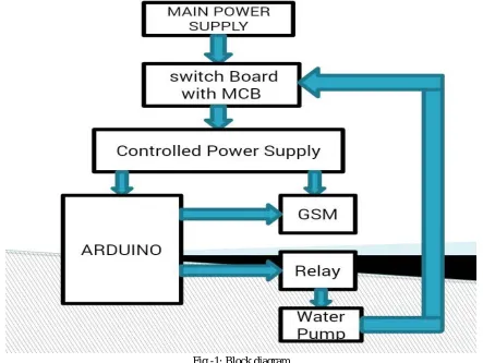
A. Main Power SupplyIt is a 230 v ac power supply.
B. Switch Board With MCB
[image:3.612.85.528.202.535.2]This switch board has two sockets. One is connected to main power supply and the pump is connected to the second socket. The two sockets are connected with each other via relay which is driven by Arduino. MCB is also connected between the two sockets for safety purpose. Whenever there is some electrical fault or jamming of motor it will trip and break the connection of second socket from first to turn the motor off.
Fig -1: Block diagram
C. Controlled Power Supply
This is connected to the first socket. Here we are using a step down transformer which steps down the 230 v ac to 9v/1A dc to power up the Arduino and GSM module.
D. Arduino
This part is heart of our project. It has a microcontroller unit (ATEMEGA 168) .It does everything from turning on the motor to send error sms to farmer.
E. GSM Module
GSM module receives call and sms from operator and sends back the error sms to the operator.
F. Relay
Technology (IJRASET)
[image:4.612.147.502.103.357.2]©IJRASET: All Rights are Reserved
713
Fig -2: Circuit diagram
III. COMPONENTS DESCRIPTION
The different major equipment’s used in system are enlisted below:
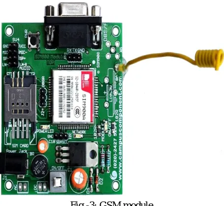
A. GSM Module
Fig -3: GSM module
[image:4.612.193.421.463.673.2]©IJRASET: All Rights are Reserved
714
with 5V Microcontrollers (PIC, AVR, Arduino, 8051, etc.) as well as 3V3 Microcontrollers (ARM, ARM Cortex XX, etc.). The baud rate can be configurable from 9600-115200 bps through AT (Attention) commands. This GSM/GPRS TTL Modem has internal TCP/IP stack to enable User to connect with internet through GPRS feature. It is suitable for SMS as well as DATA transfer application in mobile phone to mobile phone interface. The modem can be interfaced with a Microcontroller using USART (Universal Synchronous Asynchronous Receiver and Transmitter) feature (serial communication).
Features
1) Quad Band GSM/GPRS : 850 / 900 / 1800 / 1900 MHz
2) Built in RS232 to TTL or viceversa Logic Converter (MAX232)
3) Configurable Baud Rate
4) SMA (SubMiniature version A) connector with GSM L Type Antenna
5) Built in SIM (Subscriber Identity Module) Card holder
6) Built in Network Status LED
7) Audio Interface Connectors (Audio in and Audio out)
8) Most Status and Controlling pins are available
9) Normal Operation Temperature : -20 °C to +55 °C
10) Input Voltage : 5V to 12V DC
11) LDB9 connector (Serial Port) provided for easy interfacing.
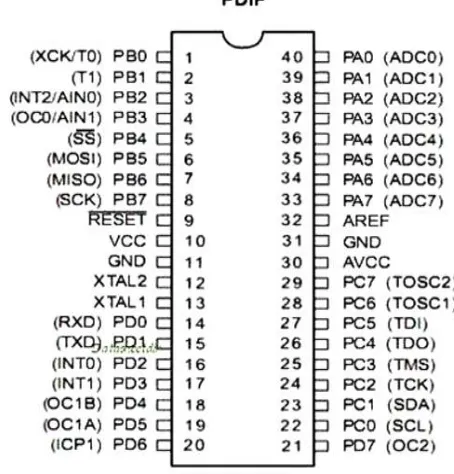
B. ATEMEGA 168
A microcontroller (sometimes abbreviated µC, uC or MCU) is a small computer on a single integrated circuit containing a processor core, memory, and programmable input/output peripherals. Microcontrollers are designed for embedded applications, in contrast to the microprocessors used in personal computers or other general purpose applications. . By reducing the size and cost compared to a design that uses a separate microprocessor, memory, and input/output devices, microcontrollers make it economical to digitally control even more devices and processes.
The AtmelAVR core combines a rich instruction set with 32 general purpose working registers. All the 32 registers are directly connected to the Arithmetic Logic Unit (ALU), allowing two independent registers to be accessed in one single instruction executed in one clock cycle. The resulting architecture is more code efficient while achieving throughputs up to ten times faster than conventional CISC microcontrollers. The ATmega8 provides the following features: 8 Kbytes of In-System Programmable Flash with Read-While-Write capabilities, 512 bytes of EEPROM, 1 Kbyte of SRAM, 23 general purpose I/O lines, 32 general purpose working registers, three flexible Timer/Counters with compare modes, internal and external interrupts, a serial programmable USART, a byte oriented Twowire Serial Interface, a 6-channel ADC (eight channels in TQFP and QFN/MLF packages) with 10-bit accuracy, a programmable Watchdog Timer with Internal Oscillator, an SPI serial port, and five software selectable power saving modes. The Idle mode stops the CPU while allowing the SRAM, Timer/Counters, SPI port, and interrupt system to continue functioning. The Powerdown mode saves the register contents but freezes the Oscillator.
Pin Descriptions
1) VCC: Digital supply voltage.
2) GND: Ground.
3) Port B (PB7:0) XTAL1/XTAL2/TOSC1/TOSC2: Port B is an 8-bit bi-directional I/O port with internal pull-up resistors
Technology (IJRASET)
[image:6.612.183.410.90.327.2]©IJRASET: All Rights are Reserved
715
Fig -4: Pin configuration of ATmega 168
Port C (PC5:0): Port C is a 7-bit bi-directional I/O port with internal pull-up resistors (selected for each bit). The PC5..0 output buffers have symmetrical drive characteristics with both high sink and source capability. As inputs, Port C pins that are externally pulled low will source current if the pull-up resistors are activated. The Port C pins are tri-stated when a reset condition becomes active, even if the clock is not running.
PC6/RESET: If the RSTDISBL Fuse is programmed, PC6 is used as an I/O pin. Note that the electrical characteristics of PC6 differ from those of the other pins of Port C. If the RSTDISBL Fuse is unprogrammed, PC6 is used as a Reset input. A low level on this pin for longer than the minimum pulse length will generate a Reset.
Port D (PD7:0): Port D is an 8-bit bi-directional I/O port with internal pull-up resistors (selected for each bit). The Port D output buffers have symmetrical drive characteristics with both high sink and source capability. As inputs, Port D pins that are externally pulled low will source current if the pull-up resistors are activated. The Port D pins are tri-stated when a reset condition becomes active, even if the clock is not running.
AVCC: AVCC is the supply voltage pin for the A/D Converter, PC3:0, and ADC7:6. It should be externally connected to VCC, even if the ADC is not used. If the ADC is used, it should be connected to VCC through a low-pass filter.
AREF: AREF is the analog reference pin for the A/D Converter.
ADC7:6: In the TQFP and QFN/MLF package, ADC7:6 serve as analog inputs to the A/D converter. These pins are powered from the analog supply and serve as 10-bit ADC channels.
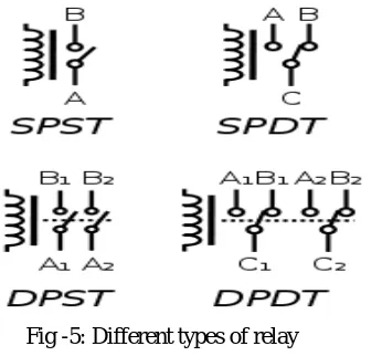
C. Relay
Relays are electromechanical devices, which are used as a switch. Current flowing through the coil of the relay creates a magnetic field which attracts a lever and changes the switch contacts. The main advantages of using relay as a switch is that, they provide electrical isolation between inputs with the help of magnetic coupling and also we can handle a large power using a relay.
There are different types of relays are available and they can be categorized in various ways. For example relays can be SPST, SPDT, DPST, DPDT etc. SPDT stands for Single Pole Double Throw.
A relay will switch one or more poles, each of whose contacts can be thrown by energizing the coil in one of three ways:
©IJRASET: All Rights are Reserved
716
It is also called aForm B contact or "break" contact. NC contacts can also be distinguished as "late-break" or NCLB, which means that the contacts will stay closed until the button or switch is fully disengaged.
Change-over (CO), or double-throw (DT), contacts control two circuits: one normally-open contact and one normally-closed contact with a common terminal. It is also called a Form C contact or "transfer" contact ("break before make"). If this type of contact utilizes a "make before break" functionality, then it is called a Form D contact.
The following designations are commonly encountered:
SPST – Single Pole Single Throw. These have two terminals which can be connected or disconnected. Including two for the coil,
such a relay has four terminals in total. It is ambiguous whether the pole is normally open or normally closed. The terminology "SPNO" and "SPNC" is sometimes used to resolve the ambiguity.
SPDT – Single Pole Double Throw. A common terminal connects to either of two others. Including two for the coil, such a relay
has five terminals in total.
DPST – Double Pole Single Throw. These have two pairs of terminals. Equivalent to two SPST switches or relays actuated by a single coil. Including two for the coil, such a relay has six terminals in total. The poles may be Form A or Form B (or one of each).
DPDT – Double Pole Double Throw. These have two rows of change-over terminals. Equivalent to two SPDT switches or relays
[image:7.612.233.406.325.486.2]actuated by a single coil. Such a relay has eight terminals, including the coil.
Fig -5: Different types of relay
IV. SOFTWARE SECTION AND EXPLAINATION
Programs for:
Remotely turning on the motor via miscall : Here we are trying to develop a code using Arduino which could detect the incoming call on GSM module and then the microcontroller turns on the relay which in turn drives the motor.
Detection of dry run and sending error sms to farmer: Here we are trying to develop a code which could detect the dry run of motor and then the microcontroller would send an error sms to farmer via GSM module.
Automatically turning off the motor in case of any other fault and alerting farmer about it via sms: We are connecting a MCB which would trip in case of any electrical fault or motor jamming and it will turn the motor off. If this happens then the microcontroller would alert the farmer about it via sms.
Remotely turning off the motor via sms: If in case farmer is busy and could not reach the field then this feature would enable him to turn the motor off via sms.
V. HARDWARE PARTS
1x GSM MODULE
1x Activated GSM SIM
Technology (IJRASET)
©IJRASET: All Rights are Reserved
717
1x Atmega 168/328p or an Arduino
1x 9v Power Supply for the Arduino/Atmega etc.
Wires (240v/120v FIRE-PROOF wires) and some scraps for the circuit-board
2x 240v terminal blocks
2x Spade connectors(for the relays) Electronics Parts:
3x 1N4001 diodes 1x 7809 regulator 1x7805 regulator 1000uf capacitor 2x 1K resistors
2x Miniature Push Switch 1x PCB
1x 9v, 1A Transformer 1x relay with 5v coil
VI. CONNECTIONS
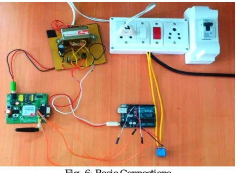
Connect the GSM Module pin Rx, Tx and GND to Arduino digital pins 11,10 and GND respectively. Attach the relay controller's "relay control" wire to the Arduino digital pin 13.
Connect a 9v power supply to the Arduino and set the power jumpers to "EXT".
[image:8.612.190.424.355.526.2]Confirm once more with the circuit diagram that everything is attached to the proper pins before continuing.
Fig -6: Basic Connections
VII. CONCLUSION
©IJRASET: All Rights are Reserved
718
REFERENCES
[1] Kay, M., “Smallholder irrigation technology: Prospects for sub-Saharan Africa” International Program and Research in Irrigation and Drainage, FAO, Rome, 2001, pp. 1–25.
[2] Fangmer, D. D., Garrot, D. J.,Mancino, C.F and Husman, S. H., “Automated irrigation systems using plant and soil sensors”, American Society of Agricultural Engineers, ASAE Publication, 1990, pp. 533-537.
[3] Joaquin Gutierrez, Juan Francisco Villa-Medina, “Automated Irrigation Using Wireless Sensor network and GPRS Module”,IEEE2014
[4] Shinghal, K., Noor, A., Srivastava, N., and Singh, R., Wireless sensor networks in agriculture for potato farming International Journal of Engineering, Science and Technology, Vol. 2, No. 8, 2010, pp. 3955-3963.