Technology (IJRASET)
©IJRASET: All Rights are Reserved
490
Analysis and Experimentation of Shell and Tube
Heat Exchanger with Different Orientation of
Baffles
Sayali R.Bhandurge 1, Prof.A.M.Wankhade2, Prof.P.K.Jadhao3, Nikhil P.Talwekar4 [1][2][3]Mechanical Engineering Department, Sant Gadge baba Amravati University
1,2,3Babasaheb Naik College of Engineering,Pusad,Maharashtra India 4
Mechanical Engineering Department,Savitribai phulePune University , Pune, India 4
Alard college of Engineering & Managment,Pune Maharashtra,India
Abstract— An Experimentation along with CFD analysis is carried on single pass, counter flow shell and tube heat exchanger containing Baffles at 00,150,300,450 orientation. To study the heat transfer rate and pressure drop of shell side fluid and compare the result with Bell-Delaware method. Experimental setup is validated with help of Dittus- Boelter correlation. Nusselt number obtain from Experimental set up of 00orientation and Dittus- Boelter correlation are within 5.72%. Experimental result of 00orientation is also compare with CFD results in which Nusselt number are found to be within 12.50% and pressure drop is found within 5.55%.Results obtain from CFD analysis is also compare with Bell Delaware method and Nu in case of CFD is 3.35% of Bell-Delaware. Pressure drop Results in case of CFD is Found within14.99%.CFD analysis of at 150,300 & 450 baffle orientation is also done and results are validate with help of Belle Delaware method. From this experimental, CFD and Bell Delaware analysis it is found that as baffle angle changes from 0 to 45 degree Nusselt no. is increases that is indirectly heat transfer rate is increase and pressure drop is reduces. As baffle orientation changes from 0 to 45 0 Nusselt number increases from 143.97 to 174.43 and pressure drop are reduces from 4956.22 Pa to 4289.71 Pa in Case of CFD Results. Reduction in Pressure drop with increase in baffle orientation help in reducing the pumping cost of Shell and tube heat exchanger.
Keywords—Nusselt number, Pressure drop, Baffle Inclination angle.
I. INTRODUCTION
A heat exchanger is a device built for efficient heat transfer from one medium to another in order to carry and process energy. The most commonly used type of heat exchanger is the shell and tube heat exchanger. It is essential to mention that a heat exchanger is not only an apparatus for transferring heat from one medium to another, but is at the same time a pressure and/or containment vessel. In addition to heating up or cooling down fluids in just a single phase, shell and tube heat exchangers can be used either to heat a liquid to evaporate (or boil) it or used as condensers to condense a vapor back to a liquid. To increase the heat transfer rate in shell and tube type heat exchanger the segmental baffles are introduced inside the cover pipe. The flow arrangement is counter flow as it is more efficient than parallel flow arrangement. One of the most important parts in shell and tube heat exchangers are the baffles.
The aim of the project is to investigate the heat transfer enhancement by different orientation of baffles in shell for increasing the heat transfer rate & achieving higher efficiency in the application of heat exchanger, nuclear reactor, solar heaters, gas turbine, combustion chamber and many other practical heating devices. . However present study permits the higher heat transfer rate but cause reasonable frictional penalty & axial pressure drop. It is proposed to make some modification to achieve heat transfer augmentation with minimum frictional losses & min. axial pressure drop. The new type of baffle inclination is intended to have high heat transfer rate & minimum pressure drop from existing. By increasing the heat transfer coefficient with the help of increasing the molecular randomness of fluid we meant making the heat transfer operation more economical and efficient. In order to achieve that, we need to modify the construction of heat exchanger,
Nomenclature
Surface area ( )
Technology (IJRASET)
©IJRASET: All Rights are Reserved
491
Outer diameter of pipe (m) Diameter of orifice (m)
h Average convective heat transfer coefficient [W/m2℃]
k Thermal conductivity[W/m℃]
L Pipe length (m)
̇ Mass flow rate of air (kg/s)
Nu Nusselt number
Pr Prandtl number
Re Reynolds number
f Friction factor
∆ Pressure drop along length of tube [N/m2]
Average surface temperature (℃) Bulk mean temperature(℃) Ti Inlet temperature(℃) To Outlet temperature(℃)
Velocity of air (m/s)
II. LITERATUREREVIEW
Verities of techniques have been implemented by researchers for heat transfer enhancement in past years for increase in heat transfer rate with low increase in pressure drop which are discussed below.
Technology (IJRASET)
©IJRASET: All Rights are Reserved
492
analyze the performance of STHX, hot fluid has made to flow through shell and cold fluid is allowed to flow through the tube. Our analysis is based on shell side study to find out temperature at the inlet and outlet of shell side, pressure drop and velocity drop. These results shows that as the mass flow rate inside the shell increases temperature drop decreases because time to transfer heat from it minimizes.So it can be concluded that most optimum result obtained at considered Baffle angle is at 8 Baffles at the mass
flow rate of 1Kg/Sec. Ankit Uppal, Dr. Vinod Kumar, Dr. Chanpreet Singh [4] studied CFD analysis of heat transfer enhancement
in a heat exchanger using various baffle arrangements. The present study reports the heat transfer enhancement in a heat exchanger
tube by installing seven different baffle arrangements. The purpose of the study is to find out the optimum baffle shape and arrangement According to results, it concluded that in case of single baffle used, rate of heat transfer is maximum for rectangular shape baffle surface and in case of baffle combinations; rate of heat transfer is maximum for rectangular and triangular baffle. The reason behind maximum heat transfer rate was that due to use of baffles, turbulence was increased as they allow more mixing of
fluid layers and resulted in increase of heat transfer through the heat exchanger tube. Avinash D Jadhav, Tushar A Koli, [5] studied
CFD analysis of shell and tube heat exchanger to study the effect of baffle cut on the pressure drop. In this paper the shell side of a small shell-and-tube heat exchanger is modelled with sufficient detail to resolve the flow and temperature fields. From the CFD simulation results, for fixed tube wall and shell inlet temperatures, shell side heat transfer coefficient, pressure drop and heat transfer rate values are obtained. The sensitivity of the shell side flow and temperature distributions to the mesh density, the order of discretization and the turbulence modelling is observed. By varying baffle cut values of 25% and 30%, for 0.5, 1 and 2 kg/s shell side flow rates, the simulation results are compared with the results from the Kern and Bell–Delaware methods. Using CFD, together with supporting experiments, may speed up the shell-and-tube heat exchanger design process and may improve the quality of the final design. In the near future, improvements in the computer technology will make full CFD simulations of much larger
shell-and-tube heat exchangers possible. Nishank Kumar Pandey, Dr. Rohit Rajvaidya [6] studied computational fluid dynamics
analysis of single pass shell & tube heat exchanger with different orientation of baffles and without baffles. In this specific project
an endeavor is design for CFD evaluation of Single Pass Shell & Tube Heat Exchanger with Different Orientation of Baffles and Without Baffles with counter flow of fluid. In order to research the performance of the heat exchanger, hot fluid was designed to flow inside the seven tubes and cold fluid flows through outer pipe & tube material using Copper as well as Brass & Shell Material using Carbon Steel. The baffles utilized in heat exchanger are usually segmental baffles cut of 25%. The introduction of baffles, force the fluid to have a turbulent flow, thus improving the heat transfer rate. The outcomes of heat transfer rate for flow of fluid with vertical segmental baffle inside heat exchanger are in comparison with the heat exchanger without having baffles. The result of
heat transfer rate & pressure drop for flow of fluid for 00 baffles is also compared with baffle at 300 orientations. They Study the
heat transfer in the heat exchanger at different velocity, the end result coming out from heat exchanger having baffles located at outer pipe will be more efficient via heat exchanger without having baffles and The outcomes of heat transfer coefficient coming out
by utilization of 30ᵒ baffles will be more efficient than 0ᵒ baffles. As the angle of inclination increases, the heat transfer rate of heat
exchanger also increases also the Reynolds number increases in the heat exchanger, the heat transfer coefficient will increase. Swarup S.Deshpande Shreeniket A Hinge [7] studied This paper primarily focuses on the design and comparative analysis of Single segmental Shell and tube Heat Exchanger with perpendicular & parallel baffle cut orientation. For designing Kern Method is used. It predicts heat transfer coefficient, Pressure drop of both arrangements. This method gives us clear idea that rate of heat transfer is greater in Perpendicular-cut baffle orientation than Parallel-cut , Pressure drop approximately remaining same. The Shell side fluid used is Lithium-bromide with average concentration of 58.5% and tube side fluid is hot water. All other parameters of fluid remaining same. From this paper it is evident that there is significant drop in the Reynolds Number corresponding to vertical flow which in turn has a direct impact on the shellside heat transfer coefficient which is found to be lower than that for horizontal flow. However the shell-side pressure drop for the vertical flow is in the same range as that for the horizontal flow design. Also there is a noticeable drop in the Nusselts Number for the proposed design with the Prandtl number being the same for both designs. Therefore based on the results we conclude that changing the flow pattern to vertical to improve the shell-side heat transfer coefficient is not
feasible. Ajithkumar M.S., Ganesha T., M. C. Math [8] studied CFDanalysis to study the effects of inclined baffles on
fluid flow in a shell and tube heat exchanger. They analyse the performance of STHX,for that hot fluid has made to flow through
Technology (IJRASET)
©IJRASET: All Rights are Reserved
493
STHX. From the CFD simulation results, the shell side outlet temperature, pressure drop, optimum baffle inclination and optimal
mass flow rate were determined.
m
Neeraj kumar, Dr. Pradeep kumar Jhinge, [9] studied effect of segmental baffles at differentorientation on the performances of single pass shell and tube heat exchanger. In this paper, experimentation of single pass, counter flow shell and tube heat exchanger containing segmental baffles at different orientations has been conducted to calculate some parameters (heat transfer rate and pressure drop) at different Reynolds number in laminar flow. In the present work, an attempt has been made to study the effect of increase in Reynolds number at different angular orientation “θ” of the baffles. The range of
“θ” vary from 0° to 45° (i.e 0°, 15°, 30° and 45°) and Reynolds number ranges from 500 to 2000 (i.e 500, 1000, 1500 and 2000). Based on the experimental result it has been observed that the angular orientation of baffles and the Reynolds number effects the heat transfer rate and pressure drop in the shell and tube heat exchanger. The heat transfer rate increases up to 30° angular orientation of the baffles and after that there is a drop in heat transfer rate at θ = 45°.
III. MATHEMATICALEQUATIONS
The Nusselt number are calculated from experimental data in turbulent flow region. Equations used for calculation of parameters are listed below.
The mass flow rate of water is calculated by,
̇= ρ
Where, ρ is the density of water, is the cross sectional area, is the velocity of water
Heat Transfer Calculation,
= . × × ( − )
The average heat transfer coefficient is calculated as
=ℎ × × ( − )
The average Nusselt number is calculated as
= ×
The Reynolds number is obtained as
=
where µ is dynamic viscosity of fluid. Prandtl number is given as
=
Equation used in Bell-Delaware Analysis,
Shell-Side Reynolds number, Res
Res=
o s
s
The maximum shell-side cross flow mass velocity, Gs
.
=
̇m
The ideal tube bank-based coefficient hi is calculated from,
ℎ = ( p)s
s s
( )s s
s
, .
heat transfer coefficient hs is expressed as,
ℎ =ℎ( × × × × )
pressure drop in the interior cross flow section,
∆pc =∆pbi(Nb-1)RlRb
pressure drop in an equivalent ideal tube bank in one baffle compartment of central baffle spacing,
∆pbi = 4 i s s,w
.
Ntcc
The pressure drop in the two end zones ∆pe
∆pe =∆pbi 1 + tcw
Technology (IJRASET)
©IJRASET: All Rights are Reserved
494
the total shell-side pressure drop Δps, excluding nozzles, is
∆ps =∆pc+∆pw+∆pe
IV. EXPERIMENTALSETUP
The schematic diagram of experimental set up is shown in fig.2. Experimental setup consists of Storage tank. Inside of tank heater coil & pump is mounted so that hot water is pumped and passes through Shell. Hot water temperature is measured with the help of
J-type thermocouple. Water is heated until 750C. Heater input is control by Dimmerstat and set at value such that constant supply of
water at 750C is obtained. Thermostat is used which shut off power to heater as 750C temperature of water exceeds. Flow control
valve (Regulator Valve & Ball valve) are used to maintain the measured of quantity flow through the test section. Orifice meter along with U –tube manometer are used to measure the mass flow rate of Fluid.5 J-type Thermocouple are used to measure inlet and outlet temperature of shell and tube fluid and to measure the surface temperature. Outer surface of test tube is well insulated with asbestos insulation to reduce convective heat loss to surrounding. Connecting pipe of 38mm diameter are used, inside of pipe orifice plate is mounted having diameter of 15mm with the help of flange arrangement. Stainless steel of SS304 material is used for Shell having outer diameter of 160mm, inner diameter of 152mm and 1000mm length of test section is used.
Fig.1: Actual Photograph of Experimental Setup
Fig.2: schematic view of Shell and Tube
Technology (IJRASET)
©IJRASET: All Rights are Reserved
495
Fig.3: 2-D view of experimental setup.
Fig.4: 0 and 450 Orientation of Baffles.
A. Baffle Inclination: Four types of Baffle inclination are used 00 Orientation of Baffle, 150 Orientation of Baffle, 300 Orientation
of Baffle 450 Orientation of Baffle. Figure3 shows 2D sketch of baffle cut with dimensions.
V. RESULT & DISCUSSION
A. Validation of experimental Setup
In the beginning, results of the present single pass counter flow Shell and tube heat exchanger with 00 orientation of baffles are
validated with those obtained from the standard empirical correlation of Dittus-Boelter as given below; Nusselt number correlation
Empirical correlation of Dittus-Boelter;
Nu = 0.023Re . Pr .
= 0.023 × (26330) . × 5.39 .
= .
% = × 100 % = . .
. × 100
= . %
It is found that Nusselt numbers obtain from present experimental setup having 00 degree orientation of baffles agree well with those
achieved from Dittus-Boelter correlation within ±5.72 %. In this way Experimental set up is first validate with standard Empirical correlation of Dittus-Boelter
B. CFD Results
Technology (IJRASET)
©IJRASET: All Rights are Reserved
496
Fig.5: Mesh Generation for 25% Baffle cut
Variation of Temperature:The temperature Contours plots across the cross section at different inclination of baffle along The length
of heat exchanger will give an idea of the flow in detail. Four different plots oftemperature Profile are taken in comparison with the
baffle inclination at 00,150,300 and 450.
Fig.6: Temperature Distribution for 00 baffle inclination.
Technology (IJRASET)
©IJRASET: All Rights are Reserved
497
[image:9.612.190.420.94.351.2]Fig.8: Temperature Distribution for 300 baffle inclination
Fig.9: Temperature Distribution for 450 baffle inclination
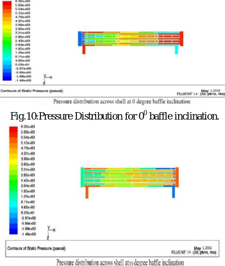
Variation of Pressure:Pressure Distribution across the shell and tube heat exchanger is given below in Figure. With the increase in
Baffle inclination angle pressure drop inside the shell is decrease. Pressure vary largely from inlet to outlet. The contours of static pressure is shown in all the
[image:9.612.190.418.427.696.2]Figure to give a detail idea.
Fig.10:Pressure Distribution for 00 baffle inclination.
Technology (IJRASET)
©IJRASET: All Rights are Reserved
498
Fig.12: Pressure Distribution for 300 baffle inclination.
Fig.13: Pressure Distribution for 450 baffle inclination.
Fig.14: Plot of Baffle inclination angle vs Outlet Temperature of shell and tube side.
0 10 20 30 40 50 60 70 80
0 20 40 60
Te
m
p
ra
tu
re
(
0C
)
Baffle Inclination Angle (Degree)
Shell side Outlet Temp
Technology (IJRASET)
©IJRASET: All Rights are Reserved
499
It has been found that there is much effect of outlet temperature of shell side with increasing the baffle inclination angle from 00 to
450.
Fig.15: Plot of Baffle angle vs Heat transfer Rate
Plot shows that with increase in baffle inclination heat transfer rate is increased.
Fig.16 Plot of Baffle angle vs Pressure Drop
The shell-side pressure drop is decreased with increase in baffle inclination angle i.e., as the Inclination angle is increased from 0° to
45°. The pressure drop is decreased by 13.44%, when baffle inclination changes from 00to 300 pressure drop is decreased by
7.3791% and when baffle inclination changes from 00to 150 Pressure drop is decreased by 5%. Hence it can be observed with
13000 13500 14000 14500 15000 15500
0 20 40 60
H ea t T ra n sf e r R a te (W )
Baffle Inclination Angle (Degree)
Heat transfer Rate 4200 4300 4400 4500 4600 4700 4800 4900 5000
0 10 20 30 40 50
P r e ss u r e D r o p (P a)
Baffle Inclination Angle (Degree)
Technology (IJRASET)
©IJRASET: All Rights are Reserved
500
[image:12.612.185.427.97.365.2]increasing baffle inclination pressure drop decreases, so that it affect in heat transfer rate which is increased.
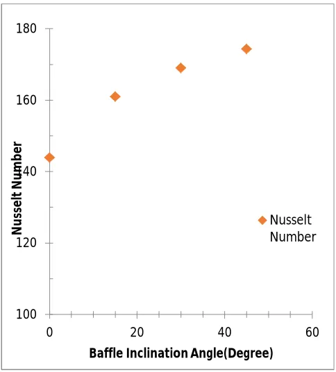
Fig.17 : Plot of Baffle angle vs Nusselt Number
Figure shows that as baffle inclination angle change from 00 to 450 Nusselt number is increased by17.4625%,whereas when baffle
inclination angle change from 00 to 300 Nusselt number increased by 14.87% and when Baffle angle change from 00 to 150 Nusselt
number increased by10.6167%. Due to change in baffle inclination angle from 00 to 450 Nusselt number is increases it means due to
change in baffle inclination heat transfer coefficient is changes, which indicates convective mode of heat transfer is increase also
fluid become more turbulence because of increase in baffle inclination from 00 to 450.
C. Comparison of Experimentation,CFD and Bell-Delaware Result,
It is found that Nusselt number obtain from present experimental setup having 00 degree of baffle orientation agree well with those
achieved from CFD analysis within ±12.50 % and with Bell-Delaware analysis is within ±15.58 % , whereas Nusselt number obtain from CFD Result and from Bell-Delaware analysis is within ± 3.5146%. Pressure drop obtain from Experimentation and
CFD analysis for 00 degree of baffle orientation is well within ± 5.55% and with Bell-Delaware analysis is within ± 9.99%, whereas
Pressure drop obtain from CFD analysis and from Bell-Delaware analysis is within ± 14.99%. It is found that Nusselt number obtain
from CFD analysis having 150 degree of baffle orientation agree well with those achieved from Bell -Delaware analysis within
±12% . Shell side pressure drop obtain from CFD analysis having 150 baffle orientation agree well with those achieved from
Bell-Delaware analysis is within ± 15.01%.Whereas due to increase in Baffle orientation from 00 to 150.Heat transfer coefficient is
increase by 10.6167%, Nusselt number is increase by 10.6167% and Shell side Pressure drop is decrease by 5% in case of CFD
analysis. In case Bell –Delaware analysis due to change in Baffle angle from 00 to 150 degree heat transfer coefficient is increase by
2% ,Nusselt number is increase by 1.99% and Shell side Pressure Drop is decrease by 5.02%. It is found that Nusselt number obtain
from CFD analysis having 300 degree of baffle orientation agree well with those achieved from Bell -Delaware analysis within
±14.91% . Shell side pressure drop obtain from CFD analysis having 300 baffle orientation agree well with those achieved from
Bell-Delaware analysis is within ± 15.36%.Whereas due to increase in Baffle orientation from 00 to 300 Heat transfer coefficient is
increase by 14.87%, Nusselt number is increase by 14.87% and Shell side Pressure drop is decrease by 7.3791% in case of CFD
analysis. In case Bell – Delaware analysis due to change in Baffle angle from 00 to 300 degree heat transfer coefficient is increase by
3.46%,Nusselt number is increase by 3.4676 % and Shell side Pressure Drop is decrease by 7.77 %. It is found that Nusselt number
obtain from CFD analysis having 450 degree of baffle orientation agree well with those achieved from Bell -Delaware analysis
within ±14.19% . Shell side pressure drop obtain from CFD analysis having 450 baffle orientation agree well with those achieved
100 120 140 160 180
0 20 40 60
N
u
ss
el
t
N
u
m
b
e
r
Baffle Inclination Angle(Degree)
Technology (IJRASET)
©IJRASET: All Rights are Reserved
501
from Bell-Delaware analysis is within ± 15.31%.Whereas due to increase in Baffle orientation from 00 to 450 Heat transfer
coefficient is increase by 17.45%, Nusselt number is increase by 17.4625% and Shell side Pressure drop is decrease by 13.44% in
case of CFD analysis. In case Bell –Delaware analysis due to change in Baffle angle from 00 to 450 degree heat transfer coefficient is
increase by 7.7364%,Nusselt number is increase by 7.184 % and Shell side Pressure Drop is decrease by 13.76 %.
Fig.17 Comparison of Pressure drop result for CFD and Bell-Delaware analysis.
Fig.18 Comparison of heat transfer coefficient result for CFD and Bell-Delaware analysis.
1000 2000 3000 4000 5000 6000
0 10 20 30 40 50
Sh e ll Si d e P re ss u re D ro p ( ∆ P ) Baffle Inclination
Shell side Pr.drop (Pa)(CFD)
Shell side Pr.drop (Pa) (Bell -Delaware) 0 100 200 300 400 500 600 700 800
0 20 40 60
Technology (IJRASET)
©IJRASET: All Rights are Reserved
502
Fig.19 Comparison of Nusselt number result for CFD and Bell-Delaware analysis.
Figure17, 18, 19 shows comparison of CFD and Bell-Delaware result in terms of heat transfer coefficient, Nusselt number and
Pressure drop. Whereas due to increase in Baffle orientation from 00 to 450 Heat transfer coefficient is increase by 17.45%, Nusselt
number is increase by 17.4625% and Shell side Pressure drop is decrease by 13.44% in case of CFD analysis. In case Bell –
Delaware analysis due to change in Baffle angle from 00 to 450 degree heat transfer coefficient is increase by 7.7364%,Nusselt
number is increase by 7.184 % and Shell side Pressure Drop is decrease by 13.76 %.
VI. CONCUSION
In the present work an Experimentation along with CFD analysis is carried on single pass, counter flow shell and tube heat
exchanger containing Baffles at 00,150,300,450 orientation. Experimental pressure drop. The results are presented in the form of
Nusselt number, heat transfer rate and pressure drop. The overall conclusions are as follows, the experimental setup is validate with Dittus-Boelter correlation. The results are in good agreement within 5.72% for Nusselt number. It is observed that, Nusselt number
with change in baffle inclination is higher than 00 baffle inclination. Nusselt number, heat transfer coefficient, heat transfer rate is
increased by 10% to 17% when baffle angle inclination changes from 00 to 450,whereas pressure drop is decreased by 5% to 13.44%
with change in baffle inclination from 00 to 450 which helps in reducing the pumping cost of shell and tube heat exchanger. Due to
change in baffle inclination angle more turbulence will be created across the shell side, because of this heat transfer coefficient is increases which results in increase of Nusselt number and hence the heat transfer rate will increase. By varying the baffle inclination
with fixed baffle spacing and the baffle cut values of 25% for 4.84 kg/sec shell side flow rates, the experimental results for 00 baffle
inclination are compared with CFD simulation result and then compare with Bell-Delaware result, it is observed that
experimentation and CFD result for 00 baffle inclination are in good agreement with Bell –Delaware results. The simulation results
for 150, 300,450baffle inclination compared with result from Bell-Delaware method. For properly spaced baffles, it is observed that
the CFD simulation results are in good agreement with the Bell-Delaware results. The results are also sensitive to baffle cut
selection, for this counter flow shell and tube heat exchanger with 10 baffles and baffle inclination of 450 gives slightly better result.
REFERENCES
[1] Sandeep K.Patel 1,Prof.Alkesh M.Mavani2, “Shell & Tube heat exchanger thermal design with optimization of mass flow rate and Baffle spacing”,International Journal of Advanced Engineering Research and studies,E-ISSN2249-8974.
[2] Koorosh Mohammadi1, Wolfgang Heidemann2 and Hans Müller-Steinhagen3, “Effect of Baffle Orientation on Heat Transfer and Pressure Drop of Shell and Tube Heat Exchanger With and Without Leakage Flow”, ICHMT International Symposium on Advances in Computational Heat Transfer, May 11-16, 2008, [3] Marrakech, Morocco. Praveen Kumar Jha, K. K. Jain ,Dr. R. K. Dave3 Pooja Tiwari4,“Analytical Performance Analysis of Shell and Tube Heat Exchanger by
0 50 100 150 200
0 20 40 60
N
u
Baffle Inclination
Nu (CFD)
Technology (IJRASET)
©IJRASET: All Rights are Reserved
503
Varying Number of Baffles and Mass Flow Rate”,IJSRD - International Journal for Scientific Research & Development| Vol. 3, Issue 04, 2015 | ISSN (online): 2321-0613 pp. 606-613.
[4] Ankit Uppal1, Dr. Vinod Kumar2, Dr. Chanpreet Singh3, “CFD analysis of heat transfer enhancement in a heat exchanger using various baffle arrangements”,
IJRMET,Vol. 4, Issue 2, May - October 2014ISSN : 2249-5762.
[5] Avinash D Jadhav, Tushar A Koli, “CFD Analysis of Shell and Tube Heat Exchanger to Study the Effect of Baffle Cut on the Pressure Drop”, International Journal of Research in Aeronautical and Mechanical Engineering, Vol. 2, Issue 7, July 2014, pp 1-7, ISSN (ONLINE): 2321-3051
[6] Nishank Kumar Pandey1, Dr. Rohit Rajvaidya2, “Computational fluid dynamics analysis of single pass shell & tube heat exchanger with different orientation of baffles and without baffles”, International journal for research in applied science and engineering technology (ijraset) August 2014 Vol. 2 Issue VIII, ISSN: 2321-9653.
[7] Swarup Deshpande1, Shreeniket A Hinge2, “Design and performance study of shell and tubeheat exchanger with single segmental bafflehaving perpendicular &
parallel-cut orientation”, International Journal of Engineering Research & Technology (IJERT), Vol. 3 Issue 11, November-2014, ISSN: 2278-018.
[8] Ajithkumar M.S.1, Ganesha T.2, M. C. Math³, “CFD analysis to study the effects of inclined baffles on fluid flow in a shell and tube heat exchanger”, International Journal of Research in Advent Technology, Vol.2, No.7, July 2014 E-ISSN: 2321-9637.