FUNDAMENTAL FREQUENCY OF HYBRID COMPOSITE PLATE EMBEDDED WITH SHAPE MEMORY ALLOY WIRE
Tan, W.C.1, S. Jamian1, M.I. Ghazali1 and N.A.N. Mohamed2 1
Department of Engineering Mechanics Universiti Tun Hussein Onn Malaysia
86400 Parit Raja, Johor, Malaysia 2
Department of Mechanical and Materials Engineering Universiti Kebangsaan Malaysia
43600 Bangi, Selangor, Malaysia
ABSTRACT
Fundamental frequency had been identified as one of the most critical parameter in vibration study which may lead to structure failure during resonance. One of the most interesting behaviors of Shape Memory Alloy (SMA) is that the fundamental frequency of the structure shifted when different temperature levels applied onto it. The fundamental frequency of hybrid composite plate embedded with the SMA wire was studied using impact hammer testing on different boundary conditions. The structure was applied with DC to the SMA wire. The results showed that the fundamental frequency and damping ratio for the hybrid composite plate were shifted and it depend on the heat level applied to the Flexinol wire and the boundary conditions of the plate. The highest value of the fundamental frequency that shifted was about 44.4% with boundary condition C-F-C-F with 0.5 A DC applied and the damping at fundamental frequency, 6.23 unit changes detected for the C-F-F-F boundary condition but with 1.25 A DC applied.
Keywords: fundamental frequency; shape memory alloy; impact hammer testing
INTRODUCTION
Shape memory alloys are widely used in the engineering applications especially in the robotic, aerospace and vibration control area. To design and optimize the applications of the shape memory alloys, a clear understanding of its behavior and characteristics are required. The fundamental frequency and damping for the structure are the major criteria to be considered when looking into the vibration area. Unfortunately these properties will only be obtained during investigation or testing.
the study, they proved that the natural frequency of the plates could be controlled by the embedded SMA actuators under a condition of heat applied. Beside that Roger (1990) has experimentally study the structural acoustic control of shape memory hybrid composites and found that the dynamic behavior, vibration amplitude, and structures could be modulated by using embedded SMA element. Few researchers (Balta et. al, 2005; Simpson et. al, 2002; Epss & Chandra, 1997; Ghomshei et al, 2005) studied the possibility of embedding the SMA wire elements into structures in order to alter the vibration frequency of the structures. Kin-Tak Lau et. al.(2002) had proposed an analytical model for the evaluation of natural frequencies of glass fiber composite beams with embedded shape memory alloy wires. In the study, they considered the changes of tensile modulus, internal recovery stress and strain, and stresses due to the thermal expansion of the beam and wire. Zak et. al.(2003) had investigated the dynamic performance of a multi-layered composite plate with embedded SMA wire in term of the changes in its relative fundamental frequency. Both active property tuning (APT) method and active strain energy tuning (ASET) method were been exploited for modeling multi-layered composite plates in the study.
In this paperwork, the fundamental frequency and damping for the hybrid composite plate embedded with the shape memory alloy wires at 0 degree will be determined from the modal analysis using the roving impact hammer testing. The structure will be clamped at different boundary conditions. The SMA wire will be heated up using DC and increased 0.25A for every repeated experiment. Further discussion on the specimen will be done in section 2 while detail experiment setup in section 3. Section 4 introduces our enhanced data and analysis, and finally the paper is concluded in section 6.
SPECIMEN
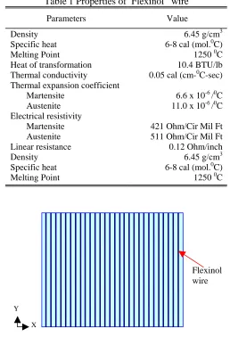
The structure is of dimension 100 mm × 100 mm × 2 mm as shown in Figure. 1, made from unsaturated polyester resin and reinforced with tissue mat glass fiber using hand lay-up technique. Details specimen preparation is similar to Tan, W.C. et. al (2006). The volume faction for the SMA wire had been designed to be 2.5%. The structure was then label with 25 point which shown in the Figure. 2.
Table1 Properties of Flexinol® wire
Parameters Value
Density 6.45 g/cm3
Specific heat 6-8 cal (mol.0C)
Melting Point 1250 0C
Heat of transformation 10.4 BTU/lb Thermal conductivity 0.05 cal (cm-0C-sec) Thermal expansion coefficient
Martensite 6.6 x 10⁻⁶ /0C
Austenite 11.0 x 10⁻⁶ /0C
Electrical resistivity
Martensite 421 Ohm/Cir Mil Ft
Austenite 511 Ohm/Cir Mil Ft
Linear resistance 0.12 Ohm/inch
Density 6.45 g/cm3
Specific heat 6-8 cal (mol.0C)
[image:3.595.167.425.130.508.2]Melting Point 1250 0C
FIGURE 1 Zero (00) degree Flexinol wire oriented hybrid composite plate. Y
X
Flexinol wire
1 2 3 4 5 6 7 8 9 10 11 13 12 14 15 16 18 17 19 20 21 23 22 24 25
[image:3.595.172.423.138.363.2]EXPERIMENT SETUP
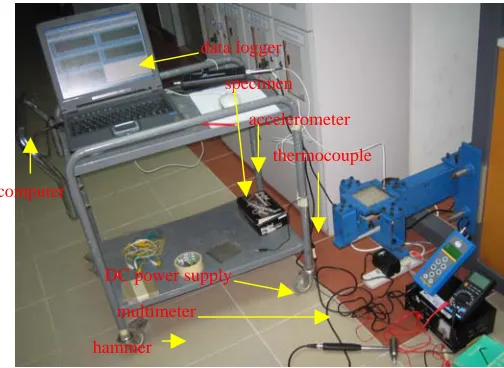
The impact hammer testing layout is shown in Figure 3. The Flexinol wire was heated up by the direct current and monitored by the digital multimeter. The temperature of the Flexinol wire was measured by the thermocouple. The roving impact hammer from PCB model DEWEN NY (716) 684-001 was used with the plastic hammer tip during the experiment.
The structure was clamped with a jig as shown in the Figure 3. The
accelerometer from Kristler model 8774A50 was placed near point 23 of the
[image:4.595.168.420.290.474.2]specimen to capture the vibration signal which generated from the impact hammer to the structure. The signal from the accelerometerwas then read by data logger 01db Symphonic before displayed at the computer with the supplied software.
FIGURE 3 Layout of experiment setup.
There are two types of testing; the testing with DC applied and without DC applied. For the test without DC, a calibration step for the roving hammer and the accelerometer need to be done first so that the software can be used to verify the signal that saved after captured. After the calibration, the impact testing can be done onto the structure.
The test began with using roving impact hammer onto the point 1 which shown in Figure 2. The signals captured by the accelerometerwithin the range set during the calibration will be accepted. The same step will be repeated to point 2 until point 25. The fresh data which saved from the software will then be exported to ME’scopeVES using *.uff format. Based on the *.uff file, ME’scopeVES able to display in FFT format and trace the fundamental frequency and other mode shape.
For the testing with DC applied, a pre-caution step needed to be taken so that the Flexinol wire did not touch the jig or other conductor surface. For every
computer
data logger
specimen
accelerometer
thermocouple
DC power supply
multimeter
repeated experiment, the DC was increased by 0.25A. The impact testing will only be conducted after the reading from the thermocouple was stable.
DATA AND ANALYSIS
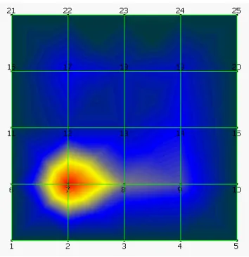
[image:5.595.203.384.228.418.2]From ME’scopeVES, FFT analysis was performed as shown in the Figure 4 and the mode shape during fundamental frequency is given in the Figure 5.
FIGURE 4 Example of FFT analysis for composite plate 0 degree without DC at all edges clamped.
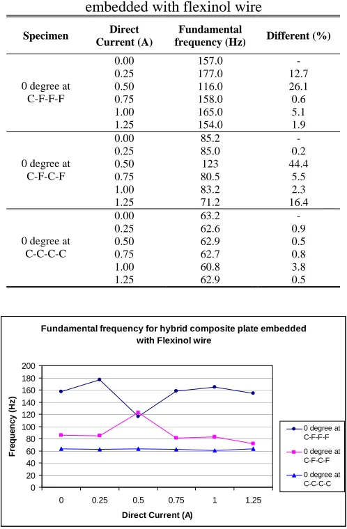
[image:5.595.210.387.464.647.2]From the FFT analysis the fundamental frequency was identified. The percentages of the fundamental frequency shifted were calculated using the condition without DC applied for each boundary condition and shown in the Table 2. The boundary conditions Free-Free-Free (C-F-F-F), Clamped-Free-Clamped-Free (C-F-C-F) and Clamped-Clamped-Clamped-Clamped (C-C-C-C) with difference DC applied to the 0 degree Flexinol wire oriented hybrid composite plate shifted the fundamental frequency. For the boundary condition C-F-C-F at 0.50A DC applied had been observed as the highest value shifted. Figure 6shows the graph of the fundamental frequency versus DC applied for the 0 degree Flexinol wire oriented hybrid composite plate at different boundary conditions.
Table 2 Fundamental frequency for 0 degree hybrid compasite plate embedded with flexinol wire
Specimen Direct Current (A)
Fundamental
frequency (Hz) Different (%)
0.00 157.0 - 0.25 177.0 12.7 0.50 116.0 26.1 0.75 158.0 0.6 1.00 165.0 5.1 0 degree at
C-F-F-F
1.25 154.0 1.9 0.00 85.2 - 0.25 85.0 0.2 0.50 123 44.4 0.75 80.5 5.5 1.00 83.2 2.3 0 degree at
C-F-C-F
1.25 71.2 16.4 0.00 63.2 - 0.25 62.6 0.9 0.50 62.9 0.5 0.75 62.7 0.8 1.00 60.8 3.8 0 degree at
C-C-C-C
1.25 62.9 0.5
Fundamental frequency for hybrid composite plate embedded with Flexinol wire
0 20 40 60 80 100 120 140 160 180 200
0 0.25 0.5 0.75 1 1.25
Direct Current (A)
Fr e que nc y ( H z )
[image:6.595.174.419.292.651.2]0 degree at C-F-F-F 0 degree at C-F-C-F 0 degree at C-C-C-C
Damping for hybrid composite plate embedded with Flexinol wire 0 1 2 3 4 5 6 7 8 9 10
0 0.25 0.5 0.75 1 1.25
Direct Current (A)
D a m p ing ( % )
0 degree at C-F-F-F 0 degree at C-F-C-F 0 degree at C-C-C-C
[image:7.595.170.420.260.649.2]During the fundamental frequency, the damping ratio for the structure were also been determined by ME’scopeVES and given in the Table 3. The damping ratio also changed with the DC applied and boundary conditions to the structure. For the boundary condition C-F-C-F, at 0.75A DC applied was the highest changes and hit the value of 8.68 from its origin of 2.67. The Figure 7 shows graphs of damping at fundamental frequency versus DC applied for the 0 degree hybrid composite plate at different boundary conditions. Both boundary conditions C-F-F-F and C-C-C-C having the similar function against the applied DC to the structure where the damping ratio decreased with the increasing DC applied to the structure.
Table 3 Damping for fundamental frequency for 0 degree hybrid compasite plate embedded with flexinol wire
Specimen Direct
Current (A) Damping Different
0.00 8.86 - 0.25 8.89 0.03 0.50 6.92 1.94 0.75 6.30 2.56 1.00 3.63 5.23 0 degree at
C-F-F-F
1.25 2.63 6.23 0.00 2.67 - 0.25 2.10 0.57 0.50 3.80 1.13 0.75 8.68 6.01 1.00 4.09 1.42 0 degree at
C-F-C-F
1.25 1.84 0.83 0.00 5.57 - 0.25 6.15 0.58 0.50 4.60 0.97 0.75 4.86 0.71 1.00 4.70 0.87 0 degree at
C-C-C-C
[image:7.595.176.417.284.525.2]1.25 5.87 0.30
CONCLUSION
Impact hammer testing can be used to determine the fundamental frequency for the hybrid composite plate without using finite element method and it is costless method where it also one of the non destructive method. This testing can be used to determine the mode shape, the fundamental frequency and the damping for the structure.
The fundamental frequencies mostly decrease for all boundary conditions when DC was started to applied onto the Flexinol wire. The fundamental frequency will also affect by the boundary condition but the all clamped case was found to detect the lowest fundamental frequency.
The boundary condition also played an important role for the damping of the hybrid composite plate where different pattern of results were displayed. For C-F-F-F case, the damping decreased with the increasing of DC but for C-C-C-C case the damping of structure increased and reached the highest value at 0.75A and then decreased.
Although this method can be used but there is still some difficulty faced such as the difficulty in controlling the temperatures during conducting the experiment especially in the process of natural cooling of the wire and in the measurement of temperature of the wire changed during the process of loading and unloading. This will affect the changes in electrical resistively of the martensite and austenite phases during the transformations.
The fundamental frequencies and the damping of the hybrid composite plate embedded with the shape memory alloy wires will be different for different boundary conditions applied onto it. For C-C-C-C condition, the fundamental frequency for the specimen is the lowest and C-F-C-F condition had been observed as the lowest value of damping most of the conditions where DC is applied onto it.
The results showed that the fundamental frequency and damping ratio for the hybrid composite plate were shifted and it depend on the heat level applied to the Flexinol wire and the boundary conditions of the plate. The highest value of the fundamental frequency that shifted was about 44.4% with boundary condition C-F-C-F with 0.5 A DC applied and the damping at fundamental frequency, 6.23 unit changes detected for the C-F-F-F boundary condition but with 1.25 A DC applied.
ACKNOWLEDGEMENTS
REFERENCES
Balta, J.A., Bosia, F., Michaud, V., Dunkel, G., Botsis, J. and Månson, J.A. 2005. Smart composites with embedded shape memory alloy actuators and fibre Bragg grating sensors: activation and control, Smart Mater. Struct. 14: 457-465.
Tan, W.C., Murni, A., Ghazali, M.I. and Jamian, S. 2006. Shape memory alloy hybrid composite plate for vibration control, International Conference on Composite and nano-Structures, Shah Alam, April 25 – 29.
Epps, J. and Chandra, R. 1997. Shape memory alloy actuation for active tuning of composite beams, Smart Mater. Struct.6: 251-264.
Ghomshei, M.M., Tabandeh, N., Ghazavi, A. and Gordaninejad, F. 2005. Nonlinear transient response of a thick composite beam with shape memory alloy layers, Composite: Part B36: 9-24.
Kin-Tak Lau, Li-Min Zhou, and Xiao-Ming Tao. 2002. Control of natural frequencies of a clamped-clamped composite beam with embedded shape memory alloy wires, Composite Structures58: 39-47.
Ostachowicz W., Krawczuk M. & Zak A.J. 1999. Natural frequencies of a
multilayer composite plate with shape memory alloy wires, Finite
Elements in Analysis and Design32: 71-83.
Roger C.A. 1990. Actice vibration and structural acoustic control of shape memory alloy hybrid composites: experimental results, J Acoust Soc Am
No 6(88): 71-83.
Simpson, J., Boller, C. 2002. in A-M.R. McGrown (Ed.),Performance of SMA-reinforced composites in an aerodynamic profile. Proceedings of SPIE;
Smart Structures and Materials 2002; Industrial and Commercial Applications of Smart Structures Technologies, vol. 4698, pp. 416-426.