A Design of Database System for STEP (AP203) Data from EXPRESS ENTITIES
1
Yusri Yusof, and
2Chen Wong Keong
1
Faculty Mechanical Engineering, Universiti Tun Hussein Onn Malaysia, Johor, 86400, MALAYSIA
2
Polytechnic Kuching Sarawak, Kuching, Sarawak, 93050 MALAYSIA
Abstract: From preliminary idea of a design until a fully functioned product, the use of data format is different in every stages of process. Data generated in design process is rich in geometry and topological format. Whereas, manufacturing process requires manufacturing feature-based data. Therefore, there is a need of a database which is not only able for storing and retrieving data, but also able to extract and separate the geometry and topological data for the use of subsequent process. This paper proposes a database system for extracting and separating the geometry and topological data from STEP AP203 (drawing file) based on EXPRESS entities and stored in the STEP database. This database system is built by using Microsoft Access relational database system. The strength of Microsoft Access relational database system is the ability to store large amounts of data in a highly normalized, tabular form, and to perform efficient quires across large data sets. Relational systems use Structured Query Language (SQL) for both data definition and data manipulation. At this moment, the database is developed by using Microsoft Access and the advantage of this database is the ability to migrate into other advanced RDBMS and this extracted geometry and topological data is beneficial for advanced STEP feature-based manufacturing process.
Key words: database system, STEP AP203, geometry and topological data, Microsoft Access
INTRODUCTION
Engineering activities are generally performed across departmental and organizational boundaries. Product development based on virtual enterprises, for example, is generally performed by several independent member companies that are physically located at different places. Information exchange and share among them is necessary. It is also true in different departments or even in different groups within a member company (Babu et al., 2010).
Information systems have become the nerve center of current computer-based engineering applications, which hereby put the requirements on engineering information modeling. Databases are design to support data storage, processing and retrieval activities related to data management, and database systems are the key to implementing engineering information modeling. Design and manufacturing companies eager to integrate their engineering processes around product databases, but engineering databases are expensive and difficult to create. Integration around product databases can enable concurrent engineering, a process where multiple engineers work on different facets of a product concurrently. However, integrated product databases are yet to be common in industry in the STEP-NC and EXPRESS entities perspective. Engineering design objects and their components are not independent. Spatio-temporal data modeling is essential in engineering design (Babu et al., 2010).
2. Material and Methods
The Standard for The Exchange of Product Model Data (STEP)
In today’s industry, product data throughout the lifecycle is often managed in different systems. Each of these systems has its own data format, so the same information is entered multiple times into different systems at different design phases leading to possible data redundancy and error. Industry vendors and users have since been seeking a common language to be used in an integrated system that can describe the entire product data throughout its lifecycle. Many solutions were proposed, the most successful being the STandard for Exchange of Product data model (STEP). STEP provides a mechanism that is capable of describing product data, independent from any particular system. The nature of this description makes it suitable not only for neutral file exchange, but also as a basis for implementing, sharing, and archiving product databases.
AP 203
ISO 10303-AP203 is the first and perhaps the most successful AP developed to exchange design data between different CAD systems (Zhao et al., 2009). After the initial release of AP203, other APs have been developed to support their particular industries. For example, AP 214 defines the core data for automotive mechanical design processes, AP 219 defines dimensional inspections, AP223 defines exchange of design and manufacturing product information for cast parts, AP 224 defines mechanical product definitions for process planning using machining features, AP 229 defines exchange of design and manufacturing product information for forged parts, AP 238 is the application interpreted model for computerized numerical controllers, and AP 240 defines process plans for machined parts (Zhao et al., 2009).
Boundary Representation
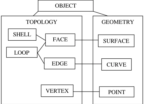
Boundary representations represent objects in terms of their ‘skin’, the boundary between ‘model’ and ‘non-model’. The skin is divided up into surface portions or faces. The faces are surrounded by sequences of edges, which are portions of curves between two adjacent surface portions. Edges, or curve portions, are delimited by vertices, which are also where faces meet. The data structure can be divided into two basic groups: one responsible for defining the structure of the object (the topological) and one the form or shape of the object (the geometry). The main elements, mentioned above, are the faces, edges, and vertices, together with their geometric forms: surface, curves, and points as shown in figure 1 (Stroud, 2010).
Fig. 1: Basic Elements Of Data Structure (Stroud, 2010)
3. Current Database Models
Engineering information modeling in databases can be carried out at two different levels: conceptual data modeling and logical database modeling. Therefore, we have conceptual data models and logical database models for engineering information modeling, respectively. Database models for engineering information modeling refer to conceptual data models and logical database models simultaneously (Babu et al., 2010).
OBJECT
TOPOLOGY GEOMETRY
[image:2.612.209.456.425.604.2]Conceptual data models
Much attention has been directed at conceptual data modeling of engineering information. Product data models, for example, can be viewed as a class of semantic data models (i.e., conceptual data models) that take into account the needs of engineering data. Recently, conceptual information modeling of enterprises such as virtual enterprises has received increasing attention. Generally speaking, traditional ER (relationship) and EER (extended entity-relationship) can be used for engineering information modeling at conceptual level (Babu et al., 2010).
Logical database model
Generic logical database systems used in engineering information modeling such as relational databases, nested relational databases, and object-oriented databases. Ahmed proposed in his paper a KSS (Kraftwerk Kennzeichen System) identification and classification system was used to develop database system for plant maintenance and management (Babu et al., 2010). Arnalte and Scala were built on top of a relational DBMS, an EXPRESS oriented information system for supporting information integration in a computer-integrated manufacturing environment (Babu et al., 2010). Goh have studied Object-oriented databases for STEP/EXPRESS. Based on the comparison with relational databases, the selections and characteristics of the object-oriented database and database management systems (OODBMS) in manufacturing were discussed in Zhang (Babu et al., 2010). Also, the formal transformation of EER and EXPRESS-G was developed in Ma. The present work propose a tool which separate the manufacturing data from STEP-NC file based on EXPRESS entities and stored in the STEP-NC manufacturing database (Babu et al., 2010).
Result And Discussion
Step AP203 Database Design
Conceptual data models are generally used for engineering information modeling at a high level of abstraction. However, engineering information systems are constructed based on logical database models. So at the level of data manipulation, that is, a low level of abstraction, the logical database model is used for engineering information modeling. Here, logical database models are often created through mapping conceptual data models into logical database models. In this conversion we used conceptual design for stores the geometry and topological data from EXPRESS entities.
Database Systems
The strength of relational database system is the ability to store large amount of data in a highly normalized, tabular form, and to perform efficient queries across large data sets (Babu et al., 2010). Relational systems use Structured Query Language (SQL) for both data definition and data manipulation. In the present work the database is developed using Microsoft Access. This database can be easily migrated into other advanced RDBMS (Babu et al., 2010).
Mapping STEP AP203 Data to Microsoft Access
The MS Access implementation uses the mapping the geometry and topological data from EXPESS entities to the relational model. Each entity is mapped to a table with columns for attributes. Each table has a column with a unique identifier for each instance. Attributes with primitive values are stored in place, and composite values like entity instances, selects, and aggregates are stored as foreign keys containing the unique instance identifier.
The MS Access primitive data types are not as extensive as those EXPRESS. Booleans and logical are approximated as Yes/No values; enumerations are stored as Text; the corresponding EXPRESS and MS Access types are shown in table I, II, III (Babu et al., 2010).
Design of EXPRESS Entity Database
Fig. 2: Geometry and topological (advanced-face) database design view
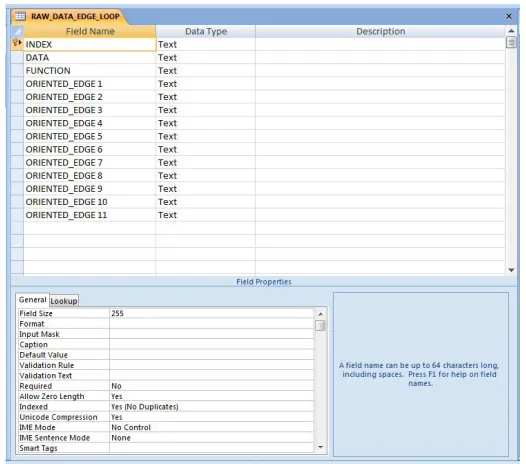
Fig. 3: Geometry and topological (edge loop) database design view
Discussion
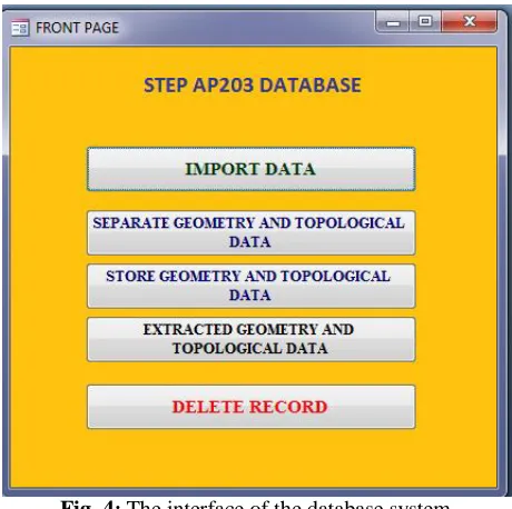
[image:4.612.193.439.71.248.2] [image:4.612.184.447.274.506.2]Fig. 4: The interface of the database system
Implementation
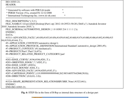
In this section, we show how to transform the STEP file from CAD for a design part. Most of the CAD systems use some form of B-Rep as their internal data structure. Examples of these systems are Pro/EngineerTM, I-DEASTM, and SolidWorksTM. The detailed data structure specific to each of these systems is different (El-Mehalawi and Allen Miller, 2003). In this project, STEP file is created from CAD system Autodesk Inventor. At first, a design part is created on Autodesk Inventer, and then save the file as *.stp, as shown in Fig.6. Then, the STEP AP203 text file in the form of B-Rep can be generated in Microsoft Notepad as shown in Fig. 7.
Implementation procedures are shown in the following steps.
Step 1: Design a part using CAD (Autodesk Inventor) and save the file as STEP file (*.stp) as shown in Fig.5. Step 2: Open the STEP file with Notepad and save as text file (*.txt) as Fig. 6.
Step 3: Import the data into the created database system
Step 4: Separate the geometry and topological data from STEP file in the following manner i. Read each line of character from the import STEP file
ii. Extract each line of geometry and topological data entity and then save them into different types of entity tables (e.g. shell table, advanced-face table, edge loop table, face table, edge table, point table and so on) Step 5: Filter and store all the parameter of the extracted geometry and topological data entity into a sensible data with using the Microsoft Access queries as shown in Fig.7.
Step 6: Display all geometry and topological data in different entity tables as shown in Fig. 8-10.
[image:5.612.200.435.535.666.2]ISO-10303-21; HEADER;
/**************************************************************** * Generated by software with PDE/Lib inside *
* PDElib Version v51a, created Fri 12/12/2008 * * International Technegroup Inc. (www.iti-oh.com) *
***************************************************************/ FILE_DESCRIPTION((''),'2;1');
FILE_NAME('C:\\Users\\Dell\\Desktop\\Part1.stp','2012-10-29T21:50:28',('Dell'),(''),'Autodesk Inventor 2010','Autodesk Inventor 2010','');
FILE_SCHEMA(('AUTOMOTIVE_DESIGN { 1 0 10303 214 1 1 1 1 }')); ENDSEC;
DATA;
#1511=ADVANCED_FACE('',(#1450,#1453,#1456,#1459,#1462,#1468,#1474,#1480,#1486,#1492,#1498,#15 04,#1510),#1444,.T.);
#5=APPLICATION_CONTEXT('automotive design');
#6=APPLICATION_PROTOCOL_DEFINITION('International Standard','automotive_design',2001,#5); #7=PRODUCT_CONTEXT('',#5,'mechanical');
#8=PRODUCT('Part1','Part1',$,(#7));
#9=PRODUCT_RELATED_PRODUCT_CATEGORY('part' ………..
#202=EDGE_CURVE('',#196,#196,#201,.T.); #203=ORIENTED_EDGE('',*,*,#202,.F.); #204=EDGE_LOOP('',(#203));
#205=FACE_BOUND('',#204,.T.);
#206=ADVANCED_FACE('',(#194,#205),#183,.F.);
#207=CARTESIAN_POINT('',(119.999999999999940,262.983160557642860,50.0)); #208=DIRECTION('',(0.0,0.0,-1.0));
…………
#1524=SHAPE_REPRESENTATION_RELATIONSHIP('SRR','None',#1523,#41); ENDSEC;
END-ISO-10303-21;
[image:6.612.66.587.70.480.2]Fig. 6: STEP file in the form of B-Rep as internal data structure of a design part
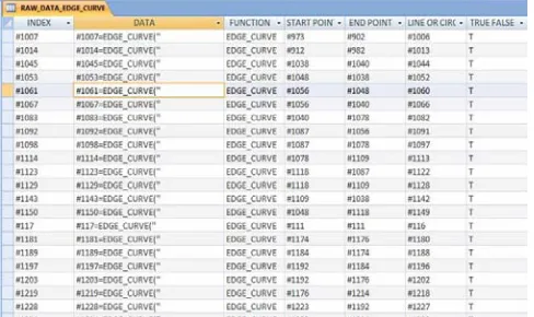
[image:6.612.197.435.473.629.2]Fig. 8: Extracted topological data (edge curve) from STEP AP203
[image:7.612.193.442.243.389.2]Fig. 9: Extracted geometry data (Cartesian point) from STEP AP203
Fig. 10: Extracted topological data (face) from STEP AP203
Conclusion
[image:7.612.190.441.413.596.2]ACKNOWLEDGEMENTS
The work reported in this paper has been supported by Research Fund of Universiti Tun Hussein Onn Malaysia (UTHM), and scholarship for Doctoral Program of Ministry of Education (MOE) of Malaysia.
REFERENCES
Abouel Nasr, E. S. & Kamrani, A. K. 2006. “A new methodology for extracting manufacturing features from CAD system. Computers & Industrial Engineering”, 51, 389-415.
Babu, K. S., Rao, D. D. N., Balakrishna, D. A. & Rao, C. S. 2010. “Development Of A Manufacturing Database System For Step-Nc Data From Express Entities. International Journal of Engineering Science and Technology”, 2 6819-6828.
El-Mehalawi, M. & Allen Miller, R.2003. “A database system of mechanical components based on geometric and topological similarity. Part I: representation. Computer-Aided Design”, 35, 83-94.
Kang, M., Han, J. & Moon, J. G. 2003. “An approach for interlinking design and process planning. Journal of Materials Processing Technology”, 139, 589-595.
Stroud, I. 2010. “Boundary Representation Modelling Techniques, Springer Publishing Company, Incorporated”.