© 2015, IRJET ISO 9001:2008 Certified Journal
Page 1152
The Role of Modular Programming in Industrial Control System
Varun
1, Ritula Thakur
21
M.E Scholar, Electrical Engineering Department, NITTTR Chandigarh (Panjab University), India
2Assistant Professor, Electrical Engineering Department, NITTTR Chandigarh (Panjab University), India
---***---Abstract -
The length of the control algorithm whichis developed for a particular plant to control its complexity increases as level of automation involved in it increases. This lengthy control algorithm is difficult to debug in case of occurrence of an error. The IEC-61131-3 programmable logic control standard has defined the concept of the modularity to overcome this problem. In this paper we use this approach to break our control algorithm into small chunks and then finally glue these chunks to implement the complete control operation.
Key Words:
Modular programming, Step-7 300/400 PLC,
digital/analog Input, digital/analog output, Fieldbus.
1.
IntroductionThe programmable logic controller is considered as the main limb of the plant automation. The PLC is defined in [1]as a microcomputer-based controlling device that uses stored instruction (i.e. control algorithm) in programmable memory to implement logic, sequencing, timing, counting and arithmetic functions through digital or analog input-output modules for controlling the machine and processes. As the size of industries grows in term of its control, the control system design proportionally starts to become more complex and distributed in nature. This is due to the reason that the number of variables involved in its control increases. Accessing the information of plant subsystem is not a big problem in the industrial domain as there are different communication techniques based on wire (for example PROFIBUS, PROFINET, MODBUS etc.) or wireless is available and is based on IEEE standards of communication. This data access bus system is known to be the field bus system in the industrial domain. The major differences between commercial office networks and industrial networks are provided in the [1]. This clearly indicates the complexity of industrial communication system over the office communication system.
The IEC-61131-3 standard is dedicated to the standardization of programming languages used in programming the PLC so that the programmer put more stress on implementation the control algorithm rather than wasting time on particular language selection. There are two text based languages and two graphical programming languages were included in this standard. One sequential flow chart language which based on the extended state machine concept is also found in it. SFC is used as a standard pathway of structuring the programs and function.
2. Hardware Description
The PLC used in the plant are either modular or embedded which depends upon the size of the plant systems. In the embedded PLC, whole functional units such as power module, DI/AI (digital/analog input) and DO/AO (digital/analog output) are included in the same functional module. The size of embedded module in terms of handing the plant input/output is limited. Where as to modular PLC are used in the bigger plant system where the need of further extension of plant could be solve by just putting a new module in the previously existing PLC. Fig. 1 provides the description of modular PLC. There are some special function modules such as CP module for efficient communication, SFM module for event counting or PID function implementation and IM module for interfacing the module to central rack. These modules can be placed on the mounting rack irrespective of simple signal module (i.e. simple DI/DO and AI/ AO).
2.1 Mounting Rack
This is a physical structure which provides support for all modules and also protects the backplane bus from physical damage. This unit restrict the number of modules on a rack.
© 2015, IRJET ISO 9001:2008 Certified Journal
Page 1153
Fig.1 Schematic diagram of a PLC
The power supply unit provides the appropriate power to the different module from the main supply which is provided by the electricity utility company. It provides 5V for CPU and 24V DC to the signal/Special function Modules in case of Siemens PLC. This ensures that, the modules are not extracting power form the measuring signal and not cause any distortion in it.
2.3 Central Processing Unit
The CPU performs the computation part of the control algorithm. The measured signal comes from the plant are acting as the process variable and enables control algorithm to perform the necessary computation. The final value of computed signal is directed towards the plant final control element with the help of output modules which take care of signals (i.e. type, magnitude etc.). The control algorithm is stored in the load memory of the CPU, which is transferred to the work memory location during the control operation.
2.4 Signal Modules
Standard Input Modules
The input modules provide the plant’s status to the operator and also act as initial step of running the control algorithm. The input modules may be digital or analog which depends upon the signal coming from the plant. [2, 3] provides more information of input and output modules.
Standard Output Modules
The output modules provide the operator to implement the control operation on the plant. The output signal may be digital or analog which depends upon control operation
which is planned to be implemented on the plant. [2, 4] provides more information of output modules.
2.5 Special Function Modules
Interfacing Modules
The interfacing modules provide a way to interface modules to the CPU. This module helps in extending the memory addressing capability of the central processing unit. If the distance between the two racks is less than 5m then the power is extracted from the P-bus where as if this distance is larger than the 5m then separated power module is used. In Siemens PLC its quantity is limited to 4 as reported in [2, 5].
Communication Processing Modules
It enables efficient communication between central control unit and remote location using different communication field bus system. CPU is even able to do the communication operation at its own, but its processing operation gets drastically effected. Hence CP relief the CPU from the communication operation and ensure that it put its strength of computation. [2, 6] provides more information of CP to the plant engineer.
Special Function Modules
These modules are used to perform some specific operation. Even standard signal modules can even do this work but it causes complex coding requirement which increases the CPU computation, unnecessary memory use and large scan time. Hence these modules perform the standard operation at their own and provides final signal to CPU. Counter module, PID modules are some of examples of them.
3. Modular Programming
The IEC 61131-3 standard of PLC is highly dedicated to its Programming. There the 2 text based and 2 graphical based programming languages mentioned in it for the programming purpose. Fig. 2 show more details of them. Sequential flow chart (graphical or test based) also called Grafcet is also mentioned in it which provides a way of structuring programs and functions blocks. More information of IEC-61131-3 standard could be found in [7-11]. The three program organisation units are defined in IEC-61131-3 standard. This POU is independent of programming languages. The POU is defined as i) Power
Supply Module
CPU
Memory unitInput Module
Output Module
Programming Device
Measured Signals
© 2015, IRJET ISO 9001:2008 Certified Journal
Page 1154
Function, ii) Function Block and Program. [12] provides [image:3.595.40.285.136.335.2]detailed information of POU, variable and constants etc.
Fig. 2 IEC 61131-3 Standard languages
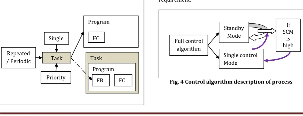
The execution of program, function and function block is taken care by the tasks as reported in [12]. Fig. 3 provides understanding of function of task. The POU accepts three input signals (i.e. single, periodic and priority) which define the execution of the control algorithm. It is even possible to call a function block which comes under the control of other task. This facility enabled inter-module accessing power.
The variables are also classified into tow group a) local, & b) global. Local variable are defined in the FB and FC. There application is limited to specific block. The global variables can be accessed throughout the program domain.
Fig.3 Modular definition of program based on IEC-61131-3 Programming Standard
There are various advantages of modular programming such as
i) Reduced algorithm development time.
ii) Easy error detection and correction in module. iii) Efficient implementation of complex control
algorithm by breaking it into small functional units.
iv) Easy understanding of program in small unit in comparison to big complex code.
v) Develop and use at the same time i.e. using some modules of code at the same time developing an individual module.
In order to demonstrate the modular programming two examples are described.
[13, 14] reported the advantages and disadvantages of all the programming languages listed in the IEC-61131-3 standard.
4. Implementation
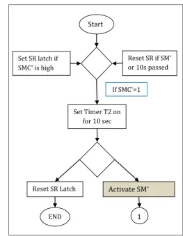
Here we used two examples to demonstrate the concept of modularity. One process is divided into two modules. Both the modules are using the function only which means that we do not prefer the function block. Fig. 4 describes the control operation implementation in the modules.
[image:3.595.34.558.567.767.2]The standby mode is defined as the initial operation mode. It is required that controller remains in this mode until it found signal that trigger it to the single control mode. These modes are names as per plant operation requirement.
Fig. 4 Control algorithm description of process Full control
algorithm
Standby Mode
Single control Mode
If SCM
is high Standard PLC
Programming Languages
Text Based Language
Graphical Language
Instruction List (IL)
Structured Text (ST)
Ladder Language
(LD) Function Block Diagram (FBD) Sequential
Flow Chart
Task
Priority Repeated
/ Periodic
Single
Task Program
FB FC
Program
© 2015, IRJET ISO 9001:2008 Certified Journal
Page 1155
The timer is also included in the control algorithm so thatafter the passage of some specific time instant the current state of plant is flashed again.
[image:4.595.296.560.153.493.2]4.1 Control Algorithm in Standby mode
Fig.5 Standby Mode logic
Where
SM* indicates the Standby Mode and
SMC* indicates the Single Mode Control
The coding of the above algorithm is down in Functional Block programming language of PLC which is a graphical programming technique. The memory block available in the CPU is used to store the initials information of the control algorithm during the process of computation. The variables are defined in the data block memory area of the
CPU memory where it is required to provide the data type of the variables.
4.2 Control Algorithm in Single Mode Control
Fig. 6 Single Control Mode
The Coding of this control algorithm is down in the other function. It gets cleared from the fig. 6 that as soon as the 10s passes in this mode the control is automatically shifted to the Standby mode. The task takes care of the proper execution of the control operation.
5. Results and Discussions
The individual function is working well in individually. The problems may arise at initially stages due to mapping of same memory location repeatedly for the computation purpose. But this error is easily overcome with proper assigning the different memory area for individual function. The individual modules are finally kept in the unconditional object block which is having the lowest priority among all object blocks. This object block is known as OB1 in Siemens PLC. The results of above algorithm can be analyzed using the simulator which is an
Start
Set SR latch if SMC* is high
Reset SR if SM*
or 10s passed
Set Timer T2 on for 10 sec
If SMC*=1
Reset SR Latch
Activate SM
*END
1
Start
Set SR latch if SM*
is high
Reset SR latch if SMC* is
high
Set timer T1 on for 10 sec
Again check SM*
and SMC* for High
If SMC* is
High
Activate SMC*
Mode Repeat previous steps
End If SMC* is
Low
If SM
*=1
[image:4.595.37.288.158.636.2]© 2015, IRJET ISO 9001:2008 Certified Journal
Page 1156
inbuilt component of the development software. Finally [image:5.595.305.561.85.359.2]the complete project t is loaded into the CPU memory that in the load memory area of the CPU. During the running of control algorithm, the copy of original code is copied to the working memory.
Fig.7 Hardware Definition
Fig.8 Standby Mode
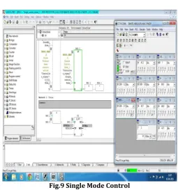
[image:5.595.41.535.172.764.2]Fig.9 Single Mode Control
Fig. 8 and 9 describes the Standby Mode and Single Mode Control. The simulator screen is placed side by to the main algorithm for easy understanding of the concepts.
6. Conclusion and Future Work
The modular programming is playing most important part in the complex control algorithms. Easy maintains, quick understanding and error correction, reduced code development time, and run while develop facility enables the control algorithm developer to follow it. But there is also a chance of occurrence of error when adopting this technique such as remembering the assigned memory location (i.e. to protect the use of same memory block to process different function at the same time). This is a common error encounter much time at initial stage. In future the stress is put on the PLC software verification which further extends the understanding of the control system reliability, verification and testing.
REFERENCES
[1] Groove, M. P. , Automation, production systems and computer-integrated manufacturing, Prentice Hall Press, 2007
[2] Berger, H, Automating with STEP-7 in LAD and FBD: Simatic S-7 300/ 400 Programmable Controllers, John Wiley & Sons.
[3] Product manual on, 6ES7321-1BL00-0AA0,
07/27/2012
[image:5.595.37.289.173.728.2]© 2015, IRJET ISO 9001:2008 Certified Journal
Page 1157
[6] Product manual on, 6ES7440-1CS00-0YE0.[7] A. Otto, K. Hellmann, IEC 61131-A General Overview and Emerging Trends, on IEEE Industrial Electronics Magazine, pp. 27-31, December 2009.
[8] K. H John and M. Tiegelkamp, IEC-61131-3 Programming Industrial Automation Systems, New York, Springer-Verlag 1995.
[9] D. Rzonca, J. Sadolewski, B. Trybus, Prototype environment for controller programming in the IEC 61131-3 ST language, in ConSIS, vol. 4, N0. 2, pp.134-148, December 2007.
[10]F.J. Molina, J. Barbarcho, C. Leon, A. Molina, and A. Gomez, Using Industrial Standards on PLC Programming Learning, in Proceeding of the 15th
Mediterranean Conference on Control and
Automation, June 27-29, 2007, Athens, Greece. [11]M. Ohman, S. Johansson, K.E. Arzen, Implementation
aspects of the PLC Standard IEC-1131-3, in Elsevier Journal on Control Engineering Practice, Vol. 6, pp. 547-555, 9 Feb. 1998.
[12] John KH, Tiegelkamp M. IEC 61131-3: programming
industrial automation systems: concepts and
programming languages, requirements for
programming systems, decision-making aids.
Springer Science & Business Media; 2010 Jun 16. [13]M. Maslar, PLC standard languages: IEC-61131-3,
IEEE Technical Conference on Pulp and Paper Industry, 10th – 14th Jun 1996, Birmingham, AL, USA.