Concurrent
CP/M™
Operating System
[!ill
DIGITAL
RESEARCHTM
Concurrent CP/M™
Operating System
COPYRIGHT
Copyright ©1984 by Digital Research Inc. All rights reserved. No part of this publication may be reproduced, transmitted, transcribed, stored in a retrieval system, or translated into any language or computer language, in any form or by any means, electronic, mechanical, magnetic, optical, chemical, manual or otherwise, ·without the prior written permission of Digital Research, Post Office Box 579, Pacific Grove, California, 93950.
DISCLAIMER
Digital Research makes no representations or warranties with respect to the contents hereof and specifically disclaims any implied warranties of merchantability or fitness for any par-ticular purpose. Further, Digital Research reserves the right to revise this publication and to make changes from time to time in the content hereof without obligation of Digital Research to notify any person of such revision or changes.
TRADEMARKS
CP/M and CP/M-86 are registered trademarks of Digital Research. ASM-86, Concurrent
CP/M, DDT, DDT-86, MP/M, MP/M-86, and PL/I are trademarks of Digital Research. Intel and MCS are registered trademarks of Intel Corporation. ISIS-II is a trademark of Intel Corporation. IBM is a registered trademark of International Business Machines.
The Concurrent CPIM Operating Syst~m Programmer's Reference Guide was printed in the United States of America.
Foreword
Concurrent CP/M@ is a multi- or single-user operating system targeted specifically for the Intel® 8086/8088/80186 family of microprocessors. It supports multiple CP/M program-ming environments each implemented on a virtual console. A different task runs concurrently in each environment.
This manual describes the invariant programming interface to Concurrent CP/M. It sup-ports the applications programmer who must create applications programs that run in the Concurrent CP/M environment.
Section 1 offers an overview of the entire operating system.
Section 2 describes the structure of the Concurrent CP/M file system.
Section 3 explains the format, structure, and uses of transient commands in the Concurrent CP/M environment.
Section 4 explains the creation of transient command files in the Concurrent CP/M envi-ronment.
Section 5 documents the structure and creation of resident system processes or resident command files permanently installed in the Concurrent CP/M environment.
. f .
Section 6 describes all the Concurrent CP/M system calls.
Concurrent CP/M is supported and documented through four manuals:
• The Concurrent CP/M Operating System User's Guide (hereinafter cited as Concurrent
CP/M User's Guide) documents the user's interface to Concurrent CP/M, explaining the various features used to execute applications programs and Digital Research utility programs .
• The Concurrent CP/M Operating System Programmer's Reference Guide (hereinafter cited as Concurrent CP/M Programmer's Reference Guide) documents the applications programmer's interface to Concurrent CP/M, explaining the internal file structure and system entry points, information that is essential for creating applications
pro-~rams that run in the Concurrent CP/M environment.
• The Concurrent CP/M Operating System Programmer's Utilities Guide (hereinafter
cited as Programmer's Utilities Guide) documents the Digital Research utility
pro-grams that programmers use to write, debug, and verify applications propro-grams written for the Concurrent CP/M environment .
• The Concurrent CP/M Operating System System Guide (hereinafter cited as Concur-rent CP/M System Guide) documents the internal, hardware-dependent structures of
Concurrent CP/M.
Table of Contents
1 Concurrent CP/M System Overview
1.1 Introduction. . . .. . . 1-1
1.2 Supervisor (SUP) ... ; 1-5
1.3 Real-time Monitor (RTM) ... 1-5
1.3.1 Process Dispatching ... 1-5
1.3.2 Queue Management... 1-7
1.3.3 System Timing Functions... 1-8
1.4 Memory Module (MEM) ... 1-9
1.5 Basic Disk Operating System (BDOS)... 1-9
1.6 Character I/O Module (CIO)... 1-10
1.7 Virtual Console Screen Management. . . 1-10
1.8 Extended Input/Output System (XIOS) ... 1-11
1. 9 Terminal Message Processes (TMP) .. .. . .. .. .. .. . . .. . .. .. . . . .. .. .. .. .. 1-12 1.10 Transient Programs... 1-12 1.11 System Call Calling Conventions... . . . 1-12 1.12 SYSTAT: System Status... 1-13
2 The Concurrent CP/M File System
2.1 File System Overview. . . 2-1
2.1.1 File-access System Calls... 2-2
2.1.2 Drive-related System Calls ... 2-3
2.2 File Naming Conventions... 2-5
2.3 Disk Drive and File Organization... 2-8
2.4 File Control Block Definition... 2-9
2.4.1 FCB Initialization and Usage... 2-12 2.4.2 File Attributes... 2-14 2.4.3 Interface Attributes . . . .. . . .. . . .. .. .. . . .. . . . .. . . .. . . . .. 2-16
2.5 User Number Conventions... 2-17
2.6 Directory Labels and XFCBs... 2-18
2.7 File Passwords. . . 2-22
2.8 File Date and Time Stamps: SFCBs... 2-24
2.9 File Open Modes... 2-26
2.10 File Security... ... 2-27 2.11 Extended File Locking... . . . .. . . 2-30 2.12 Compatibility Attributes... 2-31 2.13 Multisector I/O ... 2-34
Table of Contents
(continued)
2.14 Concurrent File Access... .. ... 2-35
2.15 File Byte Counts ... 2-37
2.16 Record Blocking and Deblocking ... :... 2-38
2.17 Reset, Access, and Free Drive... 2-39
2.18 BDOS Error Handling. . . 2-43
3 Transient Commands
3.1 Transient Program Load and Exit.. .. .. .. .. .. .. .. .. .. .. .. .. .. .. .. .. .. .. .. . 3-1
3.1.1 Shared Code... 3-2
3.1.2 8087 Support... 3-2
3.1.3 8087 Exception Handling... 3-3
3.2 Command File Format... . 3-3
3.3 Base Page Initialization... 3-5
3.4 Parent/Child Relationships ... '. . . . 3-8 3.5 Direct Video Mapping. . . 3-8
4 Command File Generation
4.1 Transient Execution Models... 4-1
4.1.1 The 8080 Memory Model... 4-2
4.1.2 The Small Memory Model... 4-4
4.1.3 The Compact Memory Model... 4-5
4.2 GENCMD ... ... ... 4-6
4.3 Intel Hexadecimal File Format... 4-9
5 Resident System Process Generation
5.1 Introduction to RSPs ... 5-1
5.2 RSP Memory Models... 5-1
5.2.1 8080 Model RSP ... 5-2
5.2.2 Small Model RSP ... 5-2
5.3 Multiple Copies of RSPs ... 5-3
5.3.1 8080 Model... 5-3
5.3.2 Small Model... 5-4
5.3.3 Small Model with Shared Code... 5-4
5.4 Creating and Initializing an RSP.. .. .. .. .. .. .. .. .. .. .. .. .. .. .. .. .. .. .. .. .. 5-4
5.4.1 The RSP Header... 5-7
Table of Contents
(continued)
5.4.2 The RSP Process Descriptor... 5-8
5.4.3 The RSP User Data Area... 5-9
5.4.4 The RSP Stack... ... ... ... 5-9
5.4.5 The RSP Command Queue... 5-9
5.4.6 Multiple Processes within an RSP ... ... 5-10
5.5 Developing and Debugging an RSP ... 5-11
6 System Calls
6.1 System Call Summary... . . . 6-13
6.2 Concurrent CP/M System Calls... 6-20
6.2.1 Console I/O System Calls... 6-21 6.2.2 Device System Calls... 6-41 6.2.3 Disk Drive System Calls... 6-44 6.2.4 File-access System Calls... 6-64 6.2.5 List Device I/O System Calls ... 6-122 6.2.6 Memory System Calls ... 6-128 6.2.7 Process/Program System Calls ... 6-139 6.2.8 Queue System Calls ... 6-162 6.2.9 System Information System Calls ... 6-174
Appendixes
A System Call Summary by Function Number.. .. .. .. .. .. .. .. .. .. .. .. .. .. .. .. .. A-I
B ASCII and Hexadecimal Conversions... .. .. .. .. .. .. .. .. .. .. .. .. .. .. .. .. .. . B-1
C Error Codes. . . C-l
D ECHO.A86 Listing. . . D-l
E 8087 Exception Handling.. . . E-l
Glossary ... Glossary-l
Index ... Index-l
Table of Contents
(continued)
Tables
1-1. Registers Used by System Calls... 1-13
2-1. File System Calls ... .
2-2. Valid Filename Delimiters ... .
2-3. Filetype Conventions ... ' .... .
2-4. Drive Capacity ... .
2-5. FCB Field Definitions ... .
2-6. File Attribute Definitions ... .
2~ 7. BDOS Interface Attributes F5' and F6' ... .
2-8. Directory Label Field Definitions ... .
2-9. XFCB Field Definitions ... , .... .
2-10. Password Protection Modes ... . 2-11. Compatibility Attribute Definitions ... . 2-12. BDOS Physical Errors ... , .... . 2-13. BDOS Extended Errors ... . 2-14. BDOS Error Codes ... . 2-15. BDOS Physical and Extended Errors ... .
2-3 2-6 2-7 2-8 2-11 2-15 2-16 2-19 2-21 2-22 2-32 2-44 2-45 2-47 2-49
3-1. Group Descriptors . . . 3-4
3-2. Group Descriptor Fields.. .. . ... .... 3-4
4-1. Concurrent CP/M Memory Models. . . 4-1
4-2. Intel Hex Field Definitions... .... 4-11
6-1. System Call Categories ... .
6-2. Concurrent CP/M System Calls ... .
6-3. System Call Summary ... .
6-4. Data· Structures Index ... .
6-5. CX Error Code Reports ... .
6-6. ACB Field Definitions ... .
6-7. C-RAWIO Calling Values ... .
6-8. Console Buffer Field Definitions ... .
6-9. C-READSTR Line-editing Characters ... .
6-10. DPB Field Definitions ... . 6-11. PFCB Field Definitions ... . 6-12. FCB Initialization ... . 6-13. MCB Field Definitions ... , .... . 6-14. MPB Field Definitions ... .
Table of Contents
(continued)
Tables
6-15. APB Field Definitions... 6-140 6-16. Command Line Buffer Field Definitions... 6-143 6-17.. PD Field Definitions.. . . 6-147 6-18. UDA Field Definitions ... '.' .. 6-152 6-19. CPB Field Definitions . . . 6-160 6-20. QPB Field Definitions... 6-163 6-21. QD Field Definitions... 6-169 6-22. SYSDAT Table Data Fields... 6-180 6-23. TOD Field Definitions... ... ... 6-186
A-I. System Call Summary by Function Number. .. .. .. .. . .. .. . .. .. . .. .. . .. .. .. .. A-I
B-1. ASCII Symbols... . . . B-1 B-2. ASCII Conversion Table... . . . .. . . B-1
C-1. Concurrent CP/M Error Codes... C-I
Figures
1-1. Concurrent CP/M Virtual/Physical Environments ... I-I
1-2. Concurrent CP/M Functional Modules... 1-3
2-1. FCB - File Control Block... 2-10
2-2. Directory Label Format. . . .. . .. . . .. . .. . .. .. . . .. .. .. .. .. . . .. .. . . .. . .. . . . 2-18
2-3. XFCB - Extended File Control Block... 2-20
2-4. Directory Record with SFCB... 2-24
2-5. SFCB Subfields... 2-24
2-6. Disk System Reset. . . 2-41
3-1. CMD File Header Format... 3-3
3-2. Group Descriptor Format... 3-3
3-3. Concurrent CP/M Base Page Values. . . 3-6
4-1. Initial Program Stack... 4-2
4-2. Concurrent CP
1M
8080 Memory Model ... 4-3Table of Contents
(continued)
4-3. Concurrent CP/M Small Memory ModeL.. . . 4-4 4-4. Concurrent CP/M Compact Memory Model... 4-5 4-5. Intel Hexadecimal File Formats... 4-10
5-1. 5-2. 5-3. 5-4. 6-1. 6-2. 6-3. 6-4. 6-5. 6-6. 6-7. 6-8. 6-9. 6-10. 6-11. 6-12. 6-13. 6-14. 6-15. 6-16. 6-17.. 6-18. 6-19. 6-20. 6-21. 6-22.
8080 and Small RSP Models ... . RSP Head Format ...•... RSP Command Queue Message ... . RSP Data Segment ... .
ACB - Assign Control Block ... . Console Buffer Format ... . Drive, RIO, or Login Vector Structure ... . DPB - Disk Parameter Block ... . Disk Free Space Field Format ... . PFCB - Parse Filename Control Block ... . MCB - Memory Control Block ... . MPB - Memory Parameter Block ... . MFPB - MJREE Parameter Block ... . APB - Abort Parameter Block ... . CLI Command Line Buffer ... . PD - Process Descriptor ... . UDA - User Data Area ... . CPB - Call Parameter Block ... . QPB - Queue Parameter Block ... . QD - Queue Descriptor ... . BDOS Version Number Format. ... . BIOS Descriptor Format ... ; ... . Operating System Version Number Format ... . SERIAL Number Format ... . SYSDAT Table ... . TOD Time-of-Day Structure ... .
Ta·ble of Contents
(continued)
Listings
6-1. Memory Control Block Definition... 6-129
6-2. Memory Parameter Block Definition... 6-130
6-3. Queue Parameter Block Definition... 6-164
D-l. ECHO .A86... D-l
E-l. 8087 Exception Handling.. .. .. .. .. .. .. .. .. .. .. .. .. .. .. .. .. .. .. .. .. .. .. .. . E-2
Section 1
Concurrent CP/M System Overview
1.1 Introduction
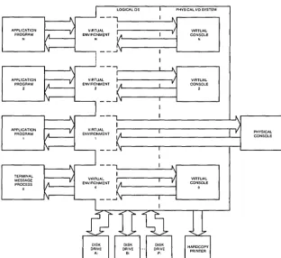
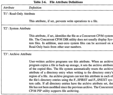
Concurrent CP/M is a multi- or single-user, multitasking operating system that lets you run multiple programs simultaneously by initiating tasks on two or more terminals or virtual consoles. Applications programs have access to system calls used by Concurrent CP/M to control the mUltiprogramming environment. As a result, Concurrent CP/M supports extended features, such as communication among and synchronization of independently running processes. Figure 1-1 depicts the relationships between applications programs, virtual environments, virtual consoles, and the user terminal.
[image:14.474.94.407.249.535.2]APPLICATION PROGRAM APPLICATION PROGRAM 2 APPLICATION PROGRAM TERMINAL MESSAGE PROCESS o
Figure 1-1.
[j]] DIGITAL RESEARCH®
VIRTUAL
ENVIRONM~NT
N
LOGICAL OS
1 I A
k
...1'1 - - - , VIRTUAL ENVIRONMENT 2 I 1,1 ( _ _ ...1 'IVIRTUAL ENVIRONMENT o I IA
k
...I~ 1 1 I I 1 I 1 I I ~ r ~ r"
VPHYSICAL I/O SYSTEM
VIRTUAL CONSOLE N VIRTUAL CONSOLE 2 VIRTUAL CONSOLE 0 PHYSICAL CONSOLE
Concurrent CP/M Virtual/Physical Environments
1.1 Introduction Concurrent CP/M Programmer's Guide
In the Concurrent CP/M environment there is an important distinction between a program and a process. A program is simply a block of code residing somewhere in memory or on disk; it is essentially static. A process, on the other hand, is a dynamic entity. You can think of it as a logical machine that executes not only the program code, but also the operating system routines necessary to support the program's functions.
When Concurrent CP/M loads a program, it creates a process associated with the loaded program. Subsequently, it is the process, rather than the program, that obtains access to the system's resources. Thus, Concurrent CP/M monitors the process, not the program. This distinction is a subtle one, but vital to your understanding of system operation as a whole.
Processes running under Concurrent CP/M fall into two categories: transient processes and Resident System Processes (RSPs). Transient processes run programs loaded into mem-ory from disk in response to a user command or system calls made by another process. Resident System Processes run code that is a part of the operating system itself. RSPs become an integral part of the operating system image during system generation. They are immediately available to perform operating system tasks. For example, the CLOCK process is an RSP that maintains the time of day within the operating system.
The following list briefly summarizes Concurrent CP/M's capabilities.
• Interprocess communication, synchronization, and mutual exclusion functions are provided by system queues.
• A logical interrupt mechanism using flags allows Concurrent CP/M to interface with any physical interrupt structure.
• System timing functions enable processes running under Concurrent CP/M to com-pute elapsed times, delay execution for specified intervals, and to access and set the current date and time.
• Shared file system allows mUltiple programs to access common data files while maintaining data integrity.
• Shared code support eliminates program loading of another copy of the same program and conserves memory space.
• 8087 support takes advantage of fast 8087 math instructions.
• Virtual console handling lets a single user run multiple programs, each in its own console environment.
• Real-time process control allows communications and data acquisition without loss of information.
- - - ' - - - I ! I D
DIGITAL RESEARCH®Concurrent CP/M Programmer's Guide 1.1 Introduction
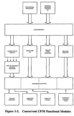
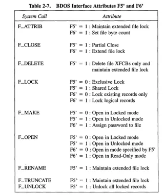
Functionally, Concurrent CP/M is composed of several distinct modules, as shown in Figure 1-2.
TERMINAL APPLICATION MESSAGE PROCESSES PROCESS xx
""'-...7
...
;:.-OS SUPERVISOR
""'-~
...
-~ ... ;.....
~;,.CHARACTER I 0 BASIC DISK MEMORY REALTIME
OS POOL
MODULE MANAGER MONITOR
I I I I
, , , ,
VIRTUAL CONSOLE SESSION MANAGER
-.:l~
... :::--..
--:::--..
.,7I I I
I I I
I I I
I EXTENDED I/O SYSTEM I
I I I
I I I
I I I
t
I t1
t
t
[image:16.470.117.371.100.494.2]SYSTEM HARDCOPY DISKETTE INTERRUPT CONSOLE PRINTER DRIVES CONTROL LOGIC
Figure 1-2. Concurrent CP/M Functional Modules
l!ID DIGITAL RESEARCHII!I
1.1 Introduction
• The Supervisor (SUP)
• The Real-time Monitor (RTM)
• The Memory Management Module (MEM) • The Character
lio
Module (CIO)iii The Virtual Console Screen Manager • The Basic Disk Operating System (BDOS)
a
The Extended 110 System (XIOS) • The Terminal Message Processor (TMP)Concurrent CP/M Programmer's Guide
The SUP module handles miscellaneous system calls such as returning the version number or the address of the System Data Area. SUP also calls other system calls when necessary.
The RTM module monitors the execution of running processes and arbitrates conflicts for the system's resources.
The MEM module allocates and frees memory upon demand from executing processes.
The CIO module handles all character I/O for console and list devices in the system.
The Virtual Console Screen Manager extends the CIO to support virtual console envi-ronments.
The BDOS is the hardware-independent module that contains the logically invariant portion of the file system for Concurrent CP/M. The BDOS file system is explained in detail in Section 2.
The XIOS is the hardware-dependent module that defines the interface of Concurrent CP / M to a specific hardware environment. See the Concurrent CP/ M System Guide for an explanation of the XIOS.
When Concurrent CP/M is executing a single program on a single virtual console, its speed approximates that of CP/M-86. But when multiple processes are running on several virtual consoles, the execution of each individual process slows according to the proportion of 110 to CPU resources it requires. A process that performs a large amount of I/O in proportion to computing exhibits only minor speed degradation. This also applies to a process that performs a large amount of computing, but runs concurrently with other processes that are largely I/O-bound. On the other hand, significant speed degradation occurs where more than one compute-bound process is running.
- - - IlIDDlGITAL RESEARCH®
Concurrent CP/M Programmer's Guide 1.2 Supervisor (SUP)
1.2 Supervisor (SUP)
The Supervisor module (SUP) manages the interface between processes and the operating system kernel. It also manages internal communication between operating system modules. All system calls, whether they originate from a transient process or internally from another system module, go through a common table-driven function interface in SUP. SUP also handles the P _LOAD (Load Process) and P _CLI (Call Command Line Interpreter) system calls.
1.3 Real-time Monitor (RTM)
The Real-time Monitor (R TM) is the real-time multitasking nucleus of Concurrent CP / M. The R TM performs process dispatching, queue management, flag management, device polling, and system timing tasks. User programs can also call many of the R TM system calls used to perform these tasks.
1.3.1 Process Dispatching
Although Concurrent CP/M is a multiprocess operating system, only one process has access to the CPU resource at any given time. Unless you specifically write a program to communicate or synchronize execution with other processes, a process is unaware of other processes competing for system resources.
The primary task of the RTM is to transfer, or dispatch, the CPU resource from one process to another. The RTM module called the Dispatcher performs this task. The RTM maintains two data structures, the Process Descriptor (PD) and the User Data Area (UDA), for each process running under Concurrent CP/M. The Dispatcher uses these data structures to save and restore the current state of each running process.
Each process in the system resides in one of three states: ready, running, or suspended. A ready process is one that is waiting for the CPU resource only. A running process is one that the CPU is currently executing. A suspended process is one that is waiting for a system resource or a specified event, such as the occurrence of an interrupt, an indication that polled hardware is ready, or the expiration of a delay period.
Any existing process is represented on a system list. The Dispatcher removes a process from one list and places it on another. The Process Descriptor of the currently running process is the first entry on the Ready List. Other processes ready to run are represented on the Ready List in order of priority. Suspended processes are on other system lists, depending on why the processes were suspended.
[Q] DIGITAL RESEARCHOli
1.3 Real-time Monitor (RTM) Concurrent CP 1M Programmer's Guide A dispatch operation can be summarized as follows:
1. The Dispatcher suspends the process from execution and stores its current state in the Process Descriptor and the UDA.
2. The Dispatcher places the process on an appropriate system list, depending on why the Dispatcher was called. For example, if a process is to delay for a certain number of system ticks, its Process Descriptor is placed on the Delay List. When a process releases a resource, the process is usually placed back on the Ready List. If another process is waiting for the resource, that process is taken off its current system list and also placed on the Ready List.
3. The highest priority process on the Ready List is chosen for execution. If two or more processes have the same priority, the process that has waited the longest executes first.
4. The Dispatcher restores the state of the selected process from its Process Descriptor and UDA, and gives it the CPU resource.
S. The process executes until it needs a busy resource, a resource needed by another process becomes available, or an interrupt occurs. At this point, a dispatch occurs, allowing another process to run.
Only processes on the Ready List are eligible for selection during dispatch. By definition, a process is on the Ready List if it is waiting only for the CPU resource. Processes waiting for other system resources cannot execute until the resources they require are available. Concurrent CP/M blocks a process from execution if it is waiting for:
• a queue message so it can complete a Q_READ operation.
• space to become available in a queue so it can complete a Q_ WRITE operation.
• a console or list device to become available.
• a specified number of system clock ticks before it can be removed from the system Delay List.
• an I/O event to complete.
These situations are discussed in greater detail in the following sections.
A running process not needing a resource and not releasing one runs until an interrupt causes a dispatch. While not all interrupts cause dispatches, the system clock generates interrupts every clock tick and forces a dispatch each time. Clock ticks usually occur 60 times a second (approximately every 16.67 milliseconds), and allow time sharing within a real-time environment.
- - - IIIDDIGITAL RESEARCH~
Concurrent CP
1M
Programmer's Guide 1.3 Real-time Monitor (RTM)Concurrent CP/M is a priority-driven system. This means that during a dispatch, the operating system gives the CPU resource to the process with the best priority. The Dispatcher allots equal shares of the system's resources to processes with the same priority. With priority dispatching, the system never passes control to a lower-priority process if there is a higher-priority process on the Ready List. Because high-higher-priority, compute-bound processes tend to monopolize the CPU resource, it is best to reduce their priority to avoid degrading overall system performance.
1.3.2 Queue Management
Queues perform several critical functions for processes ~unning under Concurrent CP/M. A process can use a queue for communicating with another process, synchronizing its execution with that of another process, and for exclusion of other processes from protected system resources. A process can make, open, delete, read from, or write to a queue with system calls similar to those used to manage disk files.
Each system queue consists of two parts: the queue descriptor, and the queue buffer. Concurrent CP/M implements these special data structures as memory files that contain room for a specified number of fixed-length messages.
When the Q_MAKE system call creates a queue, this queue is assigned a unique 8-character name. As the name queue implies, messages are read from a queue on a first-in, first-out basis.
A process can read from or write to a queue conditionally or unconditionally. If the queue is empty when a conditional read is performed, or full when a conditional write is performed, the system returns an error code to the calling process. On the other hand, if a process attempts an unconditional queue operation in these circumstances, the system suspends it from execution until the operation becomes possible.
More than one process can wait to read or write a queue message from the same queue at the same time. When these operations become possible, the system restores the highest priority process first; processes with the same priority are restored on a come, first-served basis.
Mutual exclusion queues are a special type of queue under Concurrent CP/M. They contain one message of zero length and their names follow a convention, beginning with the upper-case letters MX. A mutual exclusion queue acts as a binary semaphore, ensuring that only one process uses a resource at any time.
I!ID DIGITAL RESEARCHQP
1.3 Real-time Monitor (RTM) Concurrent CP
1M
Programmer's GuideAccess to a resource protected by a mutual exclusion queue takes place as follows:
1. A process issues an unconditional Q_READ call to the MX queue protecting the resource, thereby suspending itself if the message is not available.
2. When the message becomes available, the process accesses the protected resource. Note that from the time the process issues the unconditional read, any other process attempting to access the same resource is suspended.
3. The process writes the zero-length message back to the queue when it has finished using the protected resource, thus freeing the resource for other processes.
As an example, the system mutual exclusion queue, MXdisk, ensures that processes cannot access the file system simultaneously. Note that the BDOS, not the application software, executes the preceding series of queue calls. Therefore the mutual exclusion process is transparent to the programmer, who is only responsible for originating the disk system calls.
Mutual exclusion queues differ from normal queues in another way. When a process reads a message from a mutual exclusion queue, the RTM notes the Process Descriptor address within the Queue Descriptor. This establishes the owner of the queue message. If the operating system aborts the process while it owns the mutual exclusion message, the RTM automatically writes the message back to all mutual exclusion queues whose messages are owned by the aborted process. This grants other processes access to protected resources owned by the aborted process'.
1.3.3 System Timing Functions
Concurrent CP/M's timing system calls include keeping the time of day and delaying the execution of a process for a specified period of time. An internal process called CLOCK provides the time of day for the system. This process issues DEV _ WAITFLAG system calls . on the system's one second flag, Flag 2. When the XIOS Tick Interrupt Handler sets this flag, it initiates the CLOCK process, which then increments the internal time and date.
Subsequently" the CLOCK process makes another DEV _ WAITFLAG call and suspends itself until the flag is set again. Concurrent CP/M provides system calls that allow you to set and access the internal date and time. In addition, the file system uses the internal time and date to record when a file is updated, created, or last accessed.
- - - [ ! I D
DIGITAL RESEARCH®Concurrent CP
1M
Programmer's Guide 1.3 Real-time Monitor (RTM)The P _DELAY system call replaces the typical programmed delay loop for delaying process execution. P _DELAY requires that Flag 1, the system tick flag, be set approximately every 16.67 milliseconds, or 60 times a second; the XIOS Tick Interrupt Handler also sets this flag. When a process makes a P _DELAY system call, it specifies the number of ticks for which the operating system is to suspend it from execution. The system maintains the address of the Process Descriptor for the process on an internal Delay List along with its current delay tick count. When a DEV _SETFLAG call occurs, setting Flag 1, the tick count is decremented. When the delay count goes to zero, the system removes the process from the Delay List and places it on the Ready List.
Note: The length of a tick might vary from installation to installation. For instance, in Europe, a tick is commonly 20 milliseconds, yielding 50 ticks per second. The description of the P _DELAY system call in Section 6 describes how to determine the correct number of ticks to delay 1 second.
1.4 Memory Module (MEM)
Concurrent CP/M supports an extended, fixed partition model of memory management; the Memory Module handles all memory management system calls. In practice, the exact method that the operating system uses to allocate and free memory is transparent to the application program. Therefore you should take care to write code independent of the memory management model; use only the Concurrent CP/M specific memory system calls described in Section 6.
1.5 Basic Disk Operating System (BDOS)
Except for auxiliary device support, Concurrent CP/M BDOS is an upward-compatible version of the single-tasking CP/M-86 BDOS. It handles file creation and deletion, facilitates sequential or random file access, and allocates and frees disk space. In most cases, CP/M-86 programs that make BDOS calls for I/O can run under Concurrent CP/M without modifi-cation. Concurrent CP/M's BDOS is extended to provide support for multiple virtual consoles and list devices. In addition, the file system is extended to provide services required in a multitasking environment. The major extensions to the file system are
• File locking. Files opened under Concurrent CP/M cannot be opened or deleted by other tasks. This feature prevents accidental conflicts with other tasks.
[!ID DIGITAL RESEARCHa!I
1.5 Basic Disk Operating System (BOOS) Concurrent CP/M Programmer's Guide
• Shared access to files. As a special option, independent users can open the same file in shared or unlocked mode. Concurrent CP/M supports record locking and unlocking commands for files opened in this mode and protects files opened in shared mode from deletion by other tasks.
• Date Stamps. The BDOS optionally supports two time and date stamps, one recording when a file is updated, and the other recording when the file was created or last accessed.
• Password Protection. The password protection feature is optional at either the file or drive level. The operator or applications program assigns disk drive passwords, while application programs can assign file protection passwords in several modes.
• Extended Error Module. Besides the default error mode, Concurrent CP/M has two optional error-handling modes that return an error code to the calling process in the event of an unrecoverable disk error.
1.6 Character
1/0
Module (CIO)
The Character I/O module handles all console and list I/o. Under Concurrent CP/M, every character I/O device is associated with a data structure called a Console Control Block (CCB) or a List Control Block (LCB). These data structures reside in the XIOS. The CCB contains the current owner, status information, line editing variables, and the root of a linked list of Process Descriptors (PDs) that are waiting for access. More than one process can wait for access to a single console. These processes are maintained on a linked list of Process Descriptors in priority order. The LCBs contain similar information about the list devices. See the Concurrent CP/M System Guide for more information about LCBs and CCBs.
1.7 Virtual Console Screen Management
Virtual console screen management is coordinated by four separate modules: the CIO, the PIN (Physical INput) and VOUT (Virtual OUTput) processes, and the XIOS. The line editing associated with the C_READSTR call is performed in the CIo. The PIN process handles keyboard input for all the virtual consoles; It alSO traps and implements the CTRL-C, CTRL-S, CTRL-Q, CTRL-P, and CTRL-O functions. The VOUT process spools console output from processes running on background buffered mode consoles, and handshakes with the PIN process to display spooled console output when the background console is brought to the foreground. The XIOS decides which special keys represent the virtual consoles, and returns a special code from IO_CONIN when you request a screen switch. The XIOS also implements any screen saving and restoring when screens are switched. See the Concurrent
CP/M System Guide and the discussion of the IO_SWITCH function.
Concurrent CP/M Programmer's Guide 1.7 Virtual Console Screen Management
The PIN process reads the keyboard by directly calling the XIOS IO_CONIN function. This is the only place in the operating system IO_CONIN is called. The PIN scans the input stream from the keyboard for switch screen requests and the special function keystrokes CTRL-C, CTRL-S, CTRL-Q, CTRL-P, and CTRL-Q. All other keyboard input is written to the VINQ (Virtual Console INput Queue) associated with the foreground virtual console. The data in the VINQ becomes a type-ahead buffer for each virtual console, and is returned to the process attached to that console as it performs console input.
When PIN sees a CTRL-C it calls P _ABORT to abort the process attached to the virtual console, flushes the type-ahead buffer in the VINQ, turns off CTRL-S, and performs a DRV _RESET call for each logged-in drive. The P _ABORT call succeeds when the Process Keep flag is not on, saving the Terminal Message Processes (refer to P _CREATE for information on the process descriptor). The DRV _RESET calls affect only the removable media drives, as specified in the CKS field of the Disk Parameter Blocks in the XIOS (refer to the Concurrent CP/M System Guide for further details on Disk Parameter Blocks).
CTRL-S stops any output to the screen. CTRL-S stays set when a virtual console is switched to the background.
CTRL-O discards any console output to the virtual console. CTRL-O is turned off when any other key is subsequently pressed, except for the keys representing the virtual consoles.
CTRL-P echoes console output to the default list device specified in the LIST field of the process descriptor attached to the virtual console. If the list device is attached to a process, a PRINTER BUSY message appears.
All of the above control keys can be disabled by the C_MODE call. When one of the above control characters is disabled with C_MODE or when the process owning the virtual console is using the C_RAWIO call, the PIN does not act on the control character but instead writes it to the VINQ. It is thus possible to read any of the above control characters from an application program. These control keys are discussed in depth in the Concurrent CP/M
User's Guide.
1.8 Extended Input/Output System (XIOS)
The XIOS module is similar to the CP/M-86 Basic Input/Output System (BIOS) module, but it is extended in several ways. Primitive operations, such as console 110, are modified to support multiple virtual consoles. Several new primitive system calls, such as DEV _POLL, support Concurrent CP/M's additional features, including elimination of wait loops for real-time 110 operations.
[!QJ DIGITAL RESEARCHaII
1.9 Terminal Message Processes (TMP) Concurrent CP/M Programmer's Guide
1.9 Terminal Message Processes (TMP)
The Concurrent CP/M Terminal Message Processes (TMPs) are resident system processes that accept command lines from the virtual consoles and call the Command Line Interpreter (CLI) to execute them. The TMP prints the prompt on the virtual consoles.
Each virtual console has an independent TMP defining that console's environment, includ-ing default disk, user number, printer, and console.
1.10 Transient Programs
Under Concurrent CP/M, a transient program is one that is not system-resident. The system must load such programs from disk into available memory each time they execute. The command file of a transient program is identified by the filetype CMD. When you enter. a command at the console, the operating system searches on disk for the appropriate CMD file, loads it, and initiates it. Concurrent CP/M supports three different execution models for transient programs: the 8080 Model, the Small Model, and the Compact Model. Sections 4.1.1 through 4.1.3 describe these models in detail.
1.11 System Call Calling Conventions
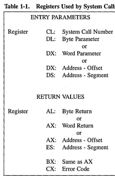
When a Concurrent CP/M process makes a system call, it loads values into the registers shown in Table 1-1 and initiates Interrupt 224 (via the INT 224 instruction), reserved by the Intel Corporation for this purpose.
- - - [!IDOIGITAL RESEARCH(J!)
Concurrent CP/M Programmer's Guide 1.11 System Call Calling Conventions
Table 1-1. Registers Used by System Calls
ENTRY PARAMETERS
Register CL: System Call Number DL: Byte Parameter
or DX: VVord Parameter
or DX: Address - Offset DS: Address - Segment
RETURN VALUES
Register AL: Byte Return or AX: VVord Return
or
AX: Address - Offset ES: Address - Segment
BX: Same as AX
ex:
Error CodeConcurrent CP/M preserves the contents of registers SI, DI, BP, SP, SS, DS, and CS through the operating system calls. The ES register is preserved when it is not used to hold a return segment value. Error codes returned in CX are shown in Table 6-5, CX Error Codes.
1.12 SYSTAT: System Status
The SYST A T utility is a development tool that shows the internal state of Concurrent CP / M. SYST A T describes memory allocation, current processes, system queue activity, and many informative parameters associated with these system data structures. Further-more, SYSTAT presents two views: either a static snapshot of system activity, or a continuous, real-time window into Concurrent CP / M.
I!ID DIGITAL RESEARCH'"
[image:26.479.150.345.51.349.2]1.12 SYST AT: System Status Concurrent CP 1M Programmer's Guide You can specify SYSTAT in one of two modes. If you know which display you want, you can specify it in the invocation, using an option shown in the menu below. If you do not specify an option, select a display from this menu by typing
A>SYSTAT <cr>
The screen clears and the main menu appears:
, Which Option?
H(elp)
M(emory)
O(verview)
P(rocesses - All)
Q(ueues)
U(ser Processes)
C(onsoles)
E(xit)
->-Press the appropriate letter to obtain a display.
When you select H(elp), the HELP file demonstrates the proper syntax and available options:
To use SYSTAT with the menu: At the system prompt type SYSTAT <CR>
To use SYSTAT without the menu: At the system prompt type the command
SYSTAT [option]
SYSTAT [option C]
-or-SYSTAT [option C
##]- - - I!IDDIGITAL RESEARCH$
Concurrent CP
1M
Programmer's Guide 1.12 SYSTAT: System Status-where-->
option
=M(emory) P(rocesses) O(verview) C(onso1es)
U(ser Processes) Q(ueues) H(elp)
->
C
=
Continuous display
~
=
1-2 digits indicating the period,
in seconds, between display refreshes.
Type any letter to return to the menu.
The M, P, Q, and U and C options ask you if you prefer a continuous display. If you type y, Concurrent CP/M asks for a time interval, in seconds, and then displays a real-time window of information. If you type n, a static snapshot of the requested information appears. In either case, press any key to return t9 the menu.
The M(emory) option displays all memory potentially' available to you, but it does not display restricted memory. The partitions are listed in memory-address order. Length param-eter is shown in paragraph values.
The O(verview) option displays an overview of the system parameters, as specified at system generation time. The display is not continuous.
The P(rocess) option displays all system processes and the resources they are using.
The Q(ueues) option displays all system queues, listing queue readers, writers, and owners.
The U(ser Processes) option displays only user-initiated processes in the same format as the P(rocess) option.
The C(onsoles) option displays console information; that is, background, foreground, buffered, suspended, purging, CTRL-Q, and so on.
The E(xit) option returns you to system level from the menu, as does CTRL-C.
End of Section 1
[Q] DIGITAL RESEARCH$
Section 2
The Concurrent CP/M File System
2.1 File System Overview
The Basic Disk Operating System (BDOS) file system supports from one to sixteen logical drives. Each logical drive has two regions: a directory area and a data area. The directory area defines the files that exist on the drive and identifies the data area space that belongs to each file. The data area contains the file data defined by the directory.
The directory area consists of sixteen logically independent directories. These directories are identified by user numbers 0 through 15. During execution, a process runs with a system parameter called the user number set to a single value. The user number specifies the current active directories for all drives on the system. For example, the Concurrent CP/M DIR utility displays only files within a directory selected by the current user number.
The file system automatically allocates directory and data area space when a process creates or extends a file, and returns previously allocated space to free space when a process deletes or truncates a file. If no directory or data space is available for a requested operation, the BDOS returns an error code to the calling process. The allocation and retrieval of directory and data space is transparent to the calling process. As a result, you need not be concerned with directory and drive organization when using the file system calls.
An eight -character filename and a three-character filetype field identify each file in a directory. Together, these fields must be unique for each file within a directory. However, files with the same filename and filetype can reside in different user directories without conflict. Processes can also assign an eight-character password to a file to protect it from unauthorized access.
i!IDDIGITAL RESEARCH<I!l
2.1 File System Overview Concurrent CP/M Programmer's Guide
All system calls that involve file operations specify the requested file by filename and filetype. For some system calls, multiple files can be specified by a technique called ambig-uous reference. This technique uses question marks and asterisks as wildcard characters to give the file system a pattern to match as it searches a directory.
The file system supports two categories of system calls: file-access system calls and drive-related system calls. The file-access system calls have mnemonics beginning with F_, and the drive-related system calls have mnemonics beginning with DRV _. The next two sections introduce the file system calls.
2.1.1 File-access System Calls
Most of the file-access system calls can be divided into two groups: system calls that operate on files within a directory and system calls that operate on records within a file. However, the file-access category also includes several miscellaneous functions that either affect the execution of other file-access system calls or are commonly used with them.
System calls in the first file-access group include calls to search for one or more files, delete one or more files, rename or truncate a file, set file attributes, assign a password to a file, and compute the size of a file. Also included in this group are system calls to open a file, to create a file, and to close a file.
The second file-access group includes system calls to read or write records to a file, either sequentially or randomly, by record position. BDOS read and write system calls transfer data in 128-byte units, which is the basic record size of the file system. This group also includes system calls to lock and unlock records and thereby allows mUltiple processes to have coordinated access to records within a commonly accessed file.
Before making read, write, lock, or unlock system calls for a file, you must first open or create the file. Creating a file has the side effect of opening the file for record access. In addition, because Concurrent CP/M supports three different modes of opening.files (Locked, Unlocked, and Read-Only), there can be other restrictions on system calls in this group that are related to the open mode. For example, you cannot write to a file that you have opened in Read-Only mode.
After a process has opened a file, access to the file by other processes is restricted until the file is closed. Again, the exact nature of the restrictions depends on the open mode. However, in all cases the file system does not allow a process to delete, rename, or change a file's attributes if another process has opened the file. Thus, the F __ CLOSE system call performs two steps to terminate record access to a file. It permanently records the current status of the file in the directory and removes the open-file restrictions limiting access to the file by other processes.
- - - I!IDDIGITAL RESEARCHI!!I
Concurrent CP/M Programmer's Guide 2.1 File System Overview
The miscellaneous file-access system calls include calls to set the current user number, set the DMA address, parse an ASCII file specification and set a default password. This group also includes system calls to set the BDOS Multisector Count and the BDOS Error Mode. The BDOS Multisector count determines the number of 128-byte records to be processed by the read, write, lock, and unlock system calls. The Multisector count can range from 1 to 128; the default value is one. The BDOS Error Mode determines whether the file system intercepts certain errors or returns on all errors to the calling process.
2.1.2 Drive-related System Calls
BDOS drive-related system calls select the default drive, compute a drive's free space, interrogate drive status, and assign a directory label to a drive. A drive's directory label controls whether the file system enforces file password protection for files in the directory.
It also specifies whether the file system is to perform date and time stamping of files on the drive.
This category also includes system calls to reset specified drives and to control whether other processes can reset particular drives. When a drive is reset, the next operation on the drive reactivates it by logging it in. Logging in a drive initializes the drive for directory and file operations. The purpose of a drive reset call is to prepare for a media change on drives that support removable media. Under Concurrent CP/M, drive reset calls are conditional. A process cannot reset a drive if another process has a file open on the drive.
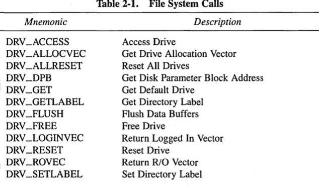
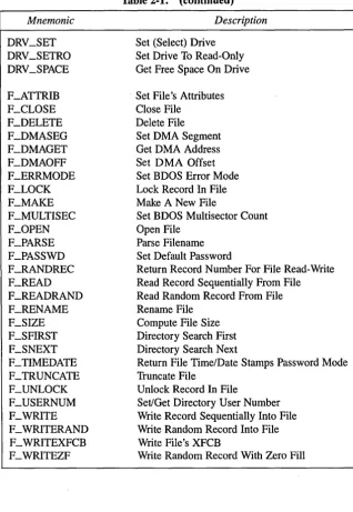
The following table summarizes the BDOS file system calls.
Mnemonic DRV_ACCESS DRV _ALLOCVEC DRV _ALLRESET DRV_DPB DRV_GET DRV_GETLABEL DRV_FLUSH DR V_FREE DRV _LOGINVEC DRV_RESET DRV_ROVEC DRV_SETLABEL
Table 2-1. File System Calls
Description
Access Drive
Get Drive Allocation Vector Reset All Drives
Get Disk Parameter Block Address Get Default Drive
Get Directory Label Flush Data Buffers Free Drive
Return Logged In Vector Reset Drive
Return RIO Vector Set Directory Label
DIGITALRESEARCH@ . . . ; . .
[image:32.469.88.405.371.555.2]2.1 File System Overview Mnemonic DRV_SET DRV_SETRO DRV_SPACE F_ATTRIB F_CLOSE F_DELETE F_DMASEG F_DMAGET F_DMAOFF F_ERRMODE F_LOCK F_MAKE F_MULTISEC F_OPEN F_PARSE F_PASSWD F_RANDREC F_READ F_READRAND F_RENAME F_SIZE F_SFIRST F_SNEXT F_TIMEDATE F_TRUNCATE F_UNLOCK F_USERNUM F_WRITE F _ WRITERAND F _ WRITEXFCB F_WRITEZF
[image:33.471.60.378.67.528.2]Concurrent CP/M Programmer's Guide
Table 2·1. (continued)
Description
Set (Select) Drive Set Drive To Read-Only Get Free Space On Drive
Set File's Attributes Close File
Delete File Set DMA Segment Get DMA Address Set DMA Offset Set BDOS Error Mode Lock Record In File Make A New File
Set BDOS Multisector Count Open File
Parse Filename Set Default Password
Return Record Number For File Read-Write Read Record Sequentially From File Read Random Record From File Rename File
Compute File Size Directory Search First Directory Search Next
Return File Time/Date Stamps Password Mode Truncate File
Unlock Record In File
Set/Get Directory User Number Write Record Sequentially Into File Write Random Record Into File Write File's XFCB
Write Random Record With Zero Fill
Concurrent CP/M Programmer's Guide 2.1 File System Overview
The following sections contain information on important topics related to the file system. Read these sections carefully before attempting to use the system calls described individually in Section 6.
2.2 File Naming Conventions
Under Concurrent CP/M, a file specification consists of four parts: a drive specifier, the filename field, the filetype field, and the file password field. The general format for a com-mand line file specification is shown below:
{d:} filename {.typ} {;password}
The drive specifier field specifies the drive where the file is located. The filename and filetype fields identify the file. The password field specifies the password if a file is password pro-tected.
The drive, type, and password fields are optional, and delimiters are required only when specifying their associated fields. The drive specifier can be assigned a letter from A to P, where the actual drive letters supported on a given system are determined by the XIOS implementation. When the drive letter is not specified, the current default drive is assumed.
The filename and password fields can contain one to eight non-delimiter characters. The filetype field can contain one to three non-delimiter characters. All three fields are left justified and padded with blanks, if necessary. Omitting the optiona] type or password fields implies a field specification of all blanks.
I!IDDIGITAL RESEARCH®
2.2 File Naming Conventions Concurrent CP/M Programmer's Guide
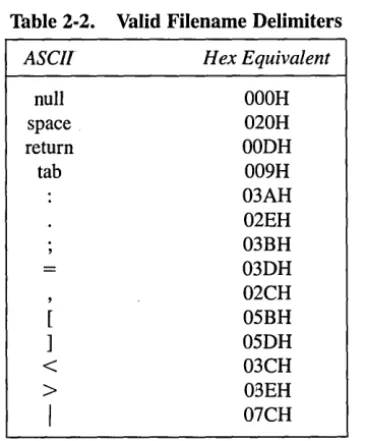
Under Concurrent CP/M, the P _CLI system call interprets ASCII command lines and loads programs. The P _CLI system call makes F _PARSE system calls to parse file specifi-cations from a command line. F _PARSE recognizes certain ASCII characters as delimiters when it parses a file specification. These characters are shown in Table 2-2.
Table 2-2. Valid Filename Delimiters
ASCII Hex Equivalent
null OOOH
space 020H
return OODH
tab 009H
03AH 02EH 03BH 03DH 02CH 05BH 05DH
<
03CH>
03EHI
07CHThe F _PARSE system call also excludes all control characters from the file specification fields and translates all lowercase letters to uppercase.
Avoid using parentheses and the backslash character, \, in the filename and filetype fields because they are commonly used delimiters. Use asterisk and question mark characters, * and ?, only to make an ambiguous file reference. When F _PARSE encounters an asterisk in a filename or filetype field, it pads the remainder of the field with question marks. For example, a filename of X* . * is parsed to X??????? . ??? The BDOS F _SFIRST, F _SNEXT, and F _DELETE system calls match a question mark in the filename or filetype fields to the corresponding position of any directory entry belonging to the current user number. Thus, a search operation for X??????? ??? finds all the files in the current user directory beginning in X. Most other file-access BDOS system calls treat the presence of a question mark in the filename or filetype fields as an error.
- - - I ! I D
DIGITAL RESEARCH® [image:35.476.135.318.132.352.2]Concurrent CP/M Programmer's Guide 2.2 File Naming Conventions
It is not mandatory to follow the file naming conventions of Concurrent CP/M when you create or rename a file with BDOS system calls directly from an application program. How-ever, the conventions must be used if the file is to be accessed from a command line. For example, the P _CLI system call cannot locate a command file in the directory if its filename or filetype field contains a lowercase letter.
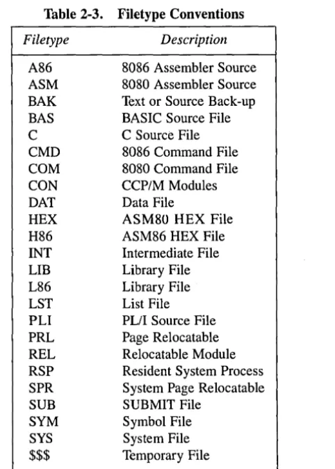
As a general rule, the filetype field names the generic category of a particular file, and the filename field distinguishes individual files within each category. Although they are generally arbitrary, Table 2-3 lists some of the generic filetype categories that have been established.
Table 2-3. Filetype Conventions
Filetype Description
A86 8086 Assembler Source ASM 8080 Assembler Source BAK Text or Source Back-up BAS BASIC Source File C C Source File CMD 8086 Command File COM 8080 Command File CON CCP/M Modules DAT Data File
HEX ASM80 HEX File H86 ASM86 HEX File INT Intermediate File LIB Library File L86 Library File LST List File PLI PL/I Source File PRL Page Relocatable REL Relocatable Module RSP Resident System Process SPR System Page Relocatable SUB SUBMIT File
SYM Symbol File SYS System File
$$$ Temporary File
[!QJ DIGITAL RESEARCH®
[image:36.474.148.389.189.526.2]2.3 Disk Drive and File Organization Concurrent CP/M Programmer's Guide
2.3 Disk Drive and File Organization
The file system can support up to sixteen logical drives, identified by the letters A through P. A logical drive usually corresponds to a physical drive on the system, particularly for physical drives that support removable media such as floppy disks .. High-capacity hard disks, however, are commonly divided into multiple logical drives. If a disk contains system tracks reserved for the boot loader, these tracks precede the tracks of the disk mapped by the logical drive. In this manual, references to drives mean logical drives, unless explicitly stated otherwise.
The maximum file size supported on a drive is 32 megabytes. The maximum capacity of a drive is determined by the data block size specified for the drive in the XIOS. The data block size is the basic unit in which the BDOS allocates space to files. Table 2-4 displays the relationship between data block size and total drive capacity.
Table 2-4. Drive Capacity
Data Block Size
lK
2K
4K 8K 16K
Maximum Drive Capacity
256 kilobytes 64 megabytes 128 megabytes 256 megabytes 512 megabytes
Each drive is divided into two regions: a directory area and a data ar~a. The directory area contains from one to sixteen blocks located at the beginning of the drive. The actual number is set in the XIOS. Directory entries residing in this area define the files that exist on the drive. In addition, the directory entries belonging to· a file identify the data blocks in the drive's data area that contain the file's records. The directory area is"logically subdivided into sixteen indepem!ent directories identified as user 0 through 15. Each independent directory shares the actual directory area on the drive.
- - - [!IDDIGITAL RESEARCH®
Concurrent CP/M Programmer's Guide 2.3 Disk Drive and File Organization
Each disk file may consist of a set of up to 262,144 (40000H) 128-byte records. Each record of a file is identified by its position in the file. This position is called the record's Random Record Number. If a file is created sequentially, the first record has a position of zero, while the last record has a position one less than the number of records in the file. Such a file can be read sequentially, beginning at record zero, or randomly by record position. Conversely, if a file is created randomly, records are added to the file by specified position. A file created in this way is called sparse if positions exist within the file where a record has not been written.
The BDOS automatically allocates data blocks to a file to contain the file's records on the basis of the record positions consumed. Thus, a sparse file that contains two records, one at position zero, the other at position 262,143, consumes only two data blocks in the data area. Sparse files can be created and accessed only randomly, not sequentially. Note that any data block allocated to a file is permanently allocated until the file is deleted or truncated. These are the only mechanisms supported by the BDOS for releasing data blocks belonging to a file.
Source files under Concurrent CP/M are treated as a sequence of ASCII characters, where each line of the source file is followed by a carriage return/line-feed sequence, ODH followed by OAH. Thus, a single 128-byte record could contain several lines of source text. The end of an ASCII file is denoted by a CTRL-Z character (lAH), or a real end-of-file, returned by the BDOS read system call. Note that these source file conventions are not supported in the file system directly but are followed by Concurrent CP/M utilities such as TYPE and ASM-86@). In addition, CTRL-Z characters embedded within other types of files such as CMD files do not signal end-of-file.
2.4 File Control Block Definition
The File Control Block (FCB) is a system data structure that serves as an important channel for information exchange between a process and BDOS file-access system calls. A process initializes an FCB to specify the drive location, fileI.1ame and filetype fields, and other infor-mation that is required to make a file-access call. For example, in an F _OPEN system call, the FCB specifies the name and location of the file to be opened. In addition, the file system uses the FCB to maintain the current state and record position of an open file. Some file-access system calls use special fields within the FCB for invoking options. Other file-file-access system calls use the FCB to return data to the calling program. All BDOS random I/O system calls require the calling process to specify the Random Record Number in a 3-byte field at the end of the FCB.
[!ID DIGITAL RESEARCH®
2.4 File Control Block Definition Concurrent CP/M Programmer's Guide
When a process makes a BDOS file-access system call, it passes an FCB address to the BDOS. This address has two 16-bit components: register DX, which contains the offset, and register DS, which contains the segment. The length of the FCB data area depends on the BDOS system call. For most system calls, the minimum length is 33 bytes. For the F _READ RAND, F _ WRITERAND, F _ WRITEZF, F _LOCK, F _UNLOCK, F _RAND REC, F_SIZE, and F_TRUNCATE system calls, the minimum FCB length is 36 bytes. When the F_OPEN or F_MAKE system calls open a file in Unlocked mode, the FCB must be at least 35 bytes long. Figure 2-1 displays the FCB data structure in two formats.
00 01 ... 09 ... 12 13 14 15 16 ... 32 33 34 35
1-+-+-+-+-+-+
OOH OR F1 F2 F3 F4 F5 F6 F7 ...
08H F8
T1 >2 >3
1
EX
1
cs1
RS
1
RC 10H 00 01 02 03 04 05 06 07 ...+--4--+--+--4--+
- - + 18H 08 09 010 011 012 013 014 01520H CR
1
RO1
R11~-4-+-"""
Figure 2·1. FCB . File Control Block
- - - [l]J DIGITAL RESEARCH®
Concurrent CP/M Programmer's Guide 2.4 File Control Block Definition
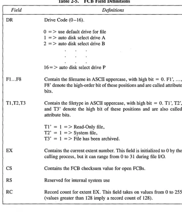
The fields in the FCB are defined as follows:
Field
DR
Fl. .. F8
Tl,T2,T3
EX
CS
RS
[image:40.475.61.434.94.537.2]RC
Table 2-5. FeB Field Definitions
Definitions
Drive Code (0-16).
o
=>
use default drive for file 1 =>
auto disk select drive A 2 =>
auto disk select drive B16
=
>
auto disk select drive PContain the filename in ASCII uppercase, with high bit
=
O. Fl', ... , F8' denote the high-order bit of these positions and are called attribute bits.Contain the filetype in ASCII uppercase, with high bit = O. Tl', T2', and T3' denote the high bit of these positions and are also called attribute bits.
Tl' 1 =
>
Read-Only file, T2' 1=
>
System file,T3' 1 =
>
File has been archived.Contains the current extent number. This field is initialized to 0 by the calling process, but it can range from 0 to 31 during file
I/o.
Contains the FCB checksum value for open FCBs.
Reserved for internal system use
Record count for extent EX. This field takes on values from 0 to 255 (values greater than 128 imply a record count of 128).
i!IDDIGITAL RESEARCH®
2.4 File Control Block Definition Concurrent CP/M Programmer's Guide
Field
DO ... D15
CR
RO,R1,R2
Table 2-5. (continued)
Definitions
Normally filled in by Concurrent CP/M and reserved for system use. Also used to specify the new filename and filetype with the F_RENAME system call.
Current record to read or write in a sequential file operation. This field is normally set to zero by the calling process when a file is opened or created.
Optional Random Record Number in the range 0-262,143 (0 - 3FFFFH). RO, R1, R2 constitute an 18-bit value with low byte RO, middle byte R1, and high byte R2.
Note: The 2-byte File ID is returned in bytes RO and R1 of the FCB when a file is suc-cessfully opened in Unlocked mode (refer to Section 2.10).
2.4.1 FeB Initialization and Usage
The calling process must initialize bytes
°
through 11 of the referenced FCB before making the following file-access system calls: F_ATTRIB, F_DELETE, F_MAKE, F_OPEN, F_RENAME, F_SFIRST, F_SIZE, F_SNEXT, F_TIMEDATE, F_TRUN-CATE, and F_ WRITEXFCB. Normally, the DR field specified the drive location of the file, and the name and type fields specify the name of the file. You must also set the EX field of the FCB before calling F _MAKE, F_OPEN, F _SFIRST, and F _ WRITEXFCB. Except for the F _ WRITEXFCB system call, you can usually set this field to zero. Note that the F_RENAME system call requires the calling process to place the new filename and filetype in bytes D 1 through D 11.The remaining file-access calls that use FCBs require an FCB that has been initialized by a prior file-access system call. For example, the F _SNEXT system call expects an FCB initialized by a prior F_SFIRST call. In addition, the F_LOCK, F_READ, F_READ-RAND, F_UNLOCK, F_WRITEF_READ-RAND, and F_WRITEZF system calls require an FCB that has been activated for record operations. Under Concurrent CP/M, only the F_OPEN and F_MAKE system calls can activate an FCB.