A Multiple Views Model for Variability Management
in Software Product Lines
R. Bashroush, I. Spence, P. Kilpatrick, TJ. Brown, C. Gillan
School of Electronics, Electrical Engineering and Computer Science
Queen’s University Belfast
{r.bashroush, i.spence, p.kilpatrick, tj.brown, c.gillan}@qub.ac.uk
Abstract
With current trends towards moving variability from hardware to software, and given the increasing desire to postpone design decisions as much as is economically feasible, managing the variability from requirements elicitation to implementation is becoming a primary business requirement in the product line process. Nowadays, a medium size software system may encompass hundreds if not thousands of variability points introducing a new level of complexity that current techniques struggle to manage. In this paper, we present a new approach to variability management by introducing a multiple views model (4VM) where each view caters for specific set of concerns that relate to a particular group of stakeholders.
1. Introduction
Within Software Product Lines, features play an important role in specifying the fixed and variable parts of the architectures of product families and configurable systems. In its simplest form, a feature is an aspect of a system, such as a behavior or an attribute, from the end user’s point of view. Feature Modeling emerged from the work by KC Kang et al [1] on domain analysis techniques.
Managing variability within the feature model is a key step for the success of a product family. Variability management is about managing the commonalities and variabilities within a product line. Commonalities are structured lists of assumptions that are true for all product members. Variabilities are structured lists of assumptions about how product members differ.
A classic example of variability is found in mobile phone product lines where variabilities include: the screen size, number of keys, language, etc.
A Variation Point identifies a variability within the product line and its possible bindings by describing several variants. A variant is a possible way to realize or bind a variation point at a specified stage of the development process (design time, compilation time, run-time, etc.) [2].
Bachmann and Bass [3] proposed a classification for architectural variabilities (Functional, Data, Control, Technology, etc.) while Svahnberg and Bosch in [4] talked about different levels of variability (Product Line, Product, Component, etc.).
As variability is geared more towards software, and as more products are being included within a single product line, current complex systems tend to comprise a large number of variability points which makes traditional manual feature modeling techniques cumbersome and difficult to use. As a result, a number of variability management techniques have emerged.
Among those are FODA [1] and FORM [5] by KC Kang et al; FeatuRSEB [6] which combined aspects of the FODA method and the Reuse-Driven Software Engineering Business (RSEB) [7] method; and Bosch’s modeling techniques [8]. Other commercial methodologies and tools include BigLever Software Gears [9] and Pure::Variants [10].
where each view caters for a specific set of concerns and relates to a particular group of stakeholders.
In the following, we begin in section 2 by discussing the scope and concerns covered by our model. Section 3 then introduces the Four Views Model (4VM) and gives details of each of the views. Finally, we draw conclusions in section 4.
2. The 4VM Scope
In this section, we discuss some variability management requirements and concerns which we have identified through experience and collaboration with other research and industrial partners. These requirements are in the form of information and relationships that should be captured about features in a feature model. The Four Views Model (4VM) is built around these concerns. More concerns can be added to the list in the future to accommodate special application domain or enterprise requirements (e.g. feature evolution, etc.).
2.1. Feature dependency
Within real-life systems, features in a model affect each other in a number of ways. Some features cannot be supported unless other feature(s) are supported in a product (mutually dependent); other features cannot be supported in the same product at the same time (mutually exclusive).
For example, consider an automobile product family where: engine size (e.g. 1.1L, 2L, etc.), gearbox (e.g. Auto, Manual – gears:4,5,6 etc.), and chassis type (sport, saloon, estate, etc.) are among the features of the product family. The number of gears in a gearbox is dependent on the engine size; so an engine size 1.1L and a 5-gear gearbox may be mutually exclusive (cannot coexist in the same product). Similarly, chassis type is dependent on the engine size; an estate chassis may require at least an engine size of 1.8L (mutually dependent).
Dependencies can be quite difficult to model, especially those that relate to quality attributes. Hence, dependencies should not only be represented as first class citizens in any feature model, but also the technique used for capturing dependencies should allow for complex dependency representation.
2.2. Feature interaction
While the presence or absence of features within a feature model may affect the existence of other features (feature dependency), feature interaction is concerned
with how different feature combinations affect the system architecture. Features are realized in an architecture using different components and configurations. Different feature combinations might lead to the inclusion of different architectural components and configurations.
For example, consider two optional features: FeatureA and FeatureB. Assume that, if FeatureA is supported by a product, it is realized in the architecture using Component1; similarly, if FeatureB is supported, it is realized in the architecture using Compnent2. Within a product that supports FeatureA, if supporting FeatureB means only the inclusion of Component2 in the product architecture, then these features are considered independent (do not interact). However, if supporting FeatureB (at the same time as FeatureA) means the inclusion of other components than Component1 and Component2 (and perhaps the exclusion of Component1 and/or Component2), then FeatureA and FeatureB are considered to be interacting features.
Predicting feature interaction in a system is a challenging task. Minimizing feature interaction is considered good practice as it reduces the architecture complexity when relating features to architectural structures. One way to minimize feature interaction is by restructuring the feature model and introducing new features to abstract those interactions (which we refer to as feature abstraction and is discussed in section 3).
2.3. Variability binding time
As discussed earlier, variation points are places in the design or implementation where variation occurs. Variability is due to unmade decisions that are left open as long as economically feasible. However, specifying the point in time when a variation point is to be bound to a specific variant is important.
A number of possible binding times have been identified and used in industry. Examples are:
- Design time: where the decision about a
variability point is made at the design stage. Beyond that point (e.g. implementation stage, run time, etc.), this variation point is not visible. An example of a design time binding is to allow for linking features to the inclusion/exclusion of architectural components as well as the reconfiguration of the architecture. This is design time variability and binding.
- Implementation time: the variation point is not
variability with C/C++ is the use of pre-processor directives. In the compiled version of the system (the executable), variability points introduced using pre-processor directives are invisible.
- Link time: this is when the variation point is not
decided upon until linking time. An example of link time variability is MS Windows Dynamic Link Libraries (DLLs).
- Load time: the variation point is not decided upon
until the load of the system. Load time variability can be introduced using a number of mechanisms such as configuration files.
- Run time: Depending on the application, this
tends to be the most desirable binding time. This is when variation points are left open until the run time when the end user can make the decision on how to bind the variability. However, due to price (cost, effort, time to implement, etc.) and complexity (complexity of the system, size of code, etc.) this is not always a feasible option. There are numerous examples of run time variability where variation points are bound including, for example, using the application’s “options” or “settings” menu.
2.4. Feature implementation time
In industry, software systems are usually built incrementally; there is rarely a software product that is built as a final release from the first edition. Products are usually enhanced and features added to them continuously over time. Planning for future releases of products, the features to be implemented in these products, and the timing, is a key step for the success and sustainability of a product line.
So, feature implementation time should also be captured within the feature model as it contributes to
product versioning.
2.5. Cost/Benefit analysis
The effort needed and cost involved in realizing features as well as their foreseen benefit should be documented in the feature model. This provides valuable input to the overall project costing and the product versioning process.
Although in general it is not an easy task to specify the cost/effort and benefit involved in realizing a given feature, adequate estimates can be obtained using information gathered and experiences gained from previous similar projects.
2.6. Open/Closed sets of features
Within industrial projects, it is rarely the case that the architect is furnished with the system’s comprehensive and complete set of features. Rather, features are continuously added (and modified) to the initial feature model over time - even after the system design process has commenced.
Designing a system around an open and changing set of features that can be modified anytime is a very challenging task. To overcome this problem, some industries differentiate between two types of features:
closed and open features.
Closed sets of features are sets of features that
cannot be changed or modified by the architect or the development team and serve as the core of the product or product line. Modifying such features requires the approval of a management appointed committee or a designated authority which would analyze the impact and feasibility of any requested modification to such features.
On the other hand, open sets of features are those that tend to change over time (for example due to technology advance or the addition of new features) and are less likely to affect the overall system when altered. Such features can be modified and changed by the project manager, architect, or the development team depending on the nature of the feature.
Such information should be clearly specified in the system feature model.
2.7. Negative features
Naturally, the development of feature models has typically focused on the features that are to be supported by a product or product line. Little attention has been paid to features that are not to be supported by a given product (or a range of products). Limiting the features supported by different products within a product line supports the development of product ranges, for example, varying from low-end products (that support a minimum number of features) to high-end ones (with most/all of the features enabled).
Negative features are features that are specified not
to be supported by a given product(s). If such negative
features are specified, the product (or product line) architecture should be designed in a way to prohibit the enabling of such features by end users of the product.
In more critical application domains, overlooking negative features could have more adverse effects. For example, overlooked negative features had more serious consequences within a US Department of Defense (DoD) funded project that was aimed at developing a GPS (Global Positioning System) based product family. The products within the family varied from low precision civilian based products to high precision high-end military versions. However, end users buying the low end civilian products, with simple tweaking of the system, were able to get access to the services and precision available for the high-end military systems.
2.8. Alternative feature names
Variability management exists at the different stages of the development life-cycle, from requirements, to architecture design and implementation. Different teams (e.g. stakeholders, architects, developers, etc.) use their own mechanisms to manage variability and to express features. So, it is possible that the same feature could be referred to by different names within different teams. Hence, it is important to keep track of the features and their alternative names within the feature model.
2.9. Feature cardinality
It is always desirable to delay design decisions as much as is economically feasible (creating variation points). However, variation points come with a price (increased complexity of the system, performance degradation, increase in cost and marketing time, etc.). One potential solution to alleviate the effect of open variation points is by attaching a limited number of possible variants that could be bound to a given variation point. This is usually referred to as feature
cardinality.
2.10. Multiple views
It is generally agreed that different stakeholders have interest in viewing different aspects (views) of the product line variability model. So, it is important for a variability management mechanism to be able to extract and present relevant information about the family model in dedicated views for different groups of stakeholders (users, system analysts, developers, etc.). This could considerably contribute to alleviating the graphical overload when showing all the information in one view (compared to multiple views). This forms the
basis of the 4VM model and is discussed in more detail in the following section.
3. 4VM
In the previous section a number of issues which need to be captured within a feature model were identified and discussed. In this section, the Four Views Model for Variability Management (4VM) is introduced. The 4VM proposes a four view presentation of the feature model. The 4VM addresses all the issues and concepts identified in the previous section. The views adopted in the 4VM model are:
- Business View: where the information related to
the project management, cost/benefit analysis, etc. is presented.
- Hierarchical & Behavioral View: where the way
the different features are organized (usually presented in a tree structure) along with the behavior attached to each feature is presented.
- Dependency & Interaction View: where the
dependency and interaction among features is presented.
- Intermediate View: where some design decisions
are injected into the feature model to take it one step further towards the architecture domain in an attempt to bridge the gap between the feature model and the system architecture.
In the following section, each of these views is discussed in detail and example views are taken from the network emulator case study [11].
3.1. Business view
The Business View is aimed at the project business and management stakeholders. It acts as a portal for inputting and presenting information related to:
- Feature implementation time - Feature Cost/Benefit analysis - Open/Closed sets of features - Negative features
These properties are usually specified and used by the project managers to carry out system-wide business analyses which support decision making such as when to introduce features within a product line; what features are feasible from a business perspective, etc. An example business view is shown in Figure 1 below.
that is one that cannot be deleted or modified by the architects/developers.
Figure 1. 4VM - Business view example
We could also see in the example above that the
Effects feature (and sub-features) is marked as closed.
This means that only a designated authority can modify this feature set (add new effects, modify existing properties, etc.). By right clicking over the feature, it is possible to change feature properties such as its cost, implementation time, etc. Also, the tool could allow for generation of project costing (based on the information contained within the feature model), feature introduction timeline (product versioning), etc.
3.2. Hierarchical & Behavioral view
The Hierarchical and Behavioral View is the view provided by most existing feature modeling techniques. In this view, information related to the structure of the feature model and the behavior of the features is captured. Among other potential users, this view is mainly targeted at architects and developers.
[image:5.612.73.294.106.297.2]Within our group, work is in progress for developing CASE tool support for this view [12] where the Use Case Maps (UCM) notation [13] is being used to model feature behavior. Figure 2 below shows an example (taken from the network emulator case study) of what is typically presented within the Hierarchical and Behavioral view.
Figure 2. 4VM - Hierarchical & Behavioural view example
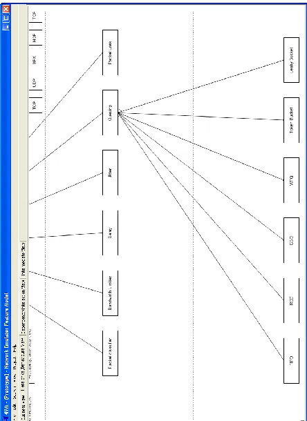
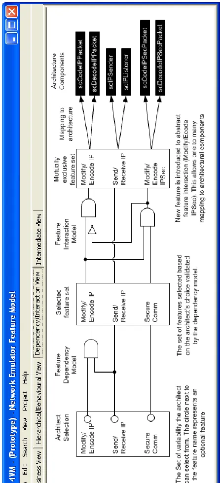
3.3. Dependency and Interaction view
Due to the size and complexity of feature dependency and interaction within real-life systems, a separate view is created within the 4VM to model these relationships. The Dependency and Interaction View is complementary to the Hierarchical and Behavioral View.
In this work, feature dependency and feature interaction are defined as follows:
- Feature Dependency: a feature-to-feature
dependency where the inclusion of one or more features affects one or more features within the system.
- Feature Interaction: a feature-to-architecture
dependency where the inclusion of one or more features affects the architecture structure (different component sets and/or configurations, etc.).
In this view, logic design is proposed to capture the dependency and interaction relationships. Once the relationships are modeled, standard logic algorithms can be used to simplify the models.
model pointing out any conflicts within the feature selection.
Once feature dependency is verified, the selected feature set is fed to the feature interaction model that outputs a new mutually exclusive set of features with new features introduced to abstract feature interaction
which is a novel approach proposed to handle feature interaction.
Returning to the network emulator case study [11], consider the “requires” relationship that exists between Modifying/encoding IP packets and Sending/Receiving IP packets. For a system to support Modifying and encoding of IP packets, it should be able to receive (and send) such packets in the first place. Assume that a new feature is to be added to the system to introduce the support for secure communication. Although secure communication (using IPSec) will not affect the sending and receiving of packets at the network level, it would require a change to the coding (encryption is added to the process) and decoding (decryption is added to the process) of IP packets. Figure 3 below shows the dependency and interaction view for IP support in the network emulator case study.
In this example, the feature dependency model captures the dependency of Modify/Ecnode IP feature
on Send/Receive IP feature. This is done using an AND
gate. If Send/Receive IP feature is not selected,
Modify/Ecnode IP feature cannot be selected. The
mapping of textual relationship description into logic circuits can be relatively straightforward where “not” maps to inverters, “and” to AND gate, and “or” to OR gate. With more complex expressions and relationships, existing logic methods and algorithms can be used at a later stage to simplify the overall model.
In Figure 3, the first column to the left shows what options the architect has to choose from. An empty circle means an optional feature.
Once the architect makes his selection, the selection is validated against the dependency model and any conflict is reflected in the second column (the middle one). The architect could then go back and choose a different feature set to resolve the conflict.
Once a non-conflicting feature set is selected, it is then passed to the interaction model where interactions are resolved by introducing new abstract features. In the example above, the Modify/Ecnode IPSec feature was introduce to abstract the interaction between
Modify/Ecnode IP feature and Secure Comm feature.
The advantage of resolving feature interaction at this stage is that it minimizes architecture complexity by making the relationship between the feature set and the architecture structure a one-to-many relationship
[image:6.612.316.539.131.621.2]rather than a many-to-many relationship. This is achieved by making the feature set a mutually independent set with the introduction of abstract features.
Figure 3. 4VM - Dependency and Interaction view example
architects. Also, textual logic expressions can be used instead of a graphical notation.
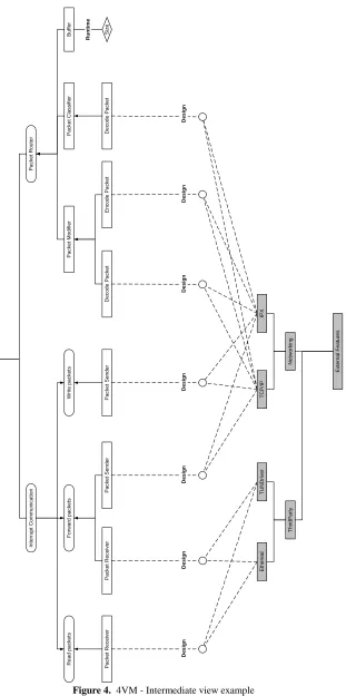
3.4. Intermediate view
Finally, the intermediate view has been introduced in an attempt to bridge the gap between feature modeling and the architecture design. This gap exists between the two domains due to the fact that the feature model is based on end-user and stakeholder concerns while the architecture structure is designed to accommodate technical concerns.
To bridge this gap, the intermediate view proposed attempts at injecting design decisions into the feature model to take it one step further towards the architecture domain. As such, it may be regarded as an intermediate stage between feature model and system architecture.
The structure of the intermediate view and the selection of the design decisions to be injected in the feature model to create the intermediate view depend heavily on the architecture design approach used. For example, in the network emulator case study [11], ADLARS [14] was used as the ADL for the architecture design and description. ADLARS partitions the space into three dimensions: Concurrency (captured within Tasks), Structure and Functionality (captured within Components) and Behavior (Captured by Interaction Themes). So, the feature model would be much easier to map to architecture structures if it shows what features are to be implemented concurrently and what features are mere functionality. By injecting such design decisions in the feature model, we end up with the intermediate view which is easier to follow at the architecture design process.
A small part (due to lack of space) of the intermediate view of the network emulator case study is shown in Figure 4 below.
Figure 4 shows three types of features:
- Concurrency features: which are features that
require a separate thread of execution each, and map to different ADLARS tasks within the system architecture description.
- Functionality features: which are features that
describe system functionality (usually as a part of a specific thread of execution) and map to ADLARS components and sub-components within the system architecture description.
- External features: these are features that are
external to the system or product family (over which we have no control) and with which the system would need to interact. These are classified in three types:
Platform: related to the platform the system is
running on (RTOS, Unix, Win32, etc.)
Third party software: e.g. TUNDrive, a piece
of third party software that provides user applications with a virtual Ethernet network interface card over Unix based systems (the one used in the network emulator case study).
Networking technologies: e.g. TCP/IP, IPX,
etc. in case our system needs to communicate over the network (which is the case for the network emulator). Also, to better identify with ADLARS (where Tasks are composed of Components, etc.), the features within the intermediate view are related in three ways:
- Composition: which is represented by a bottom up
arrow and means that a given feature is composed of the features below it. For example, the “Forward Packets” feature (Figure 4) is composed of two features, “Packet Receiver” and “Packet Sender”.
- Realization: which is represented by a top down
arrow and means that a given feature is realized or deployed by the features below it, that is, the parent feature is a template feature implemented by one of the children features. For example, the “Interrupt Communication” feature could either be: “Read Packets”, “Write Packets” or “Forward Packets”.
- Environment: which relates the variability of a
feature to an external feature (environment). For example, the “Packet Sender” feature is related to what network protocol is used (e.g. TCP/IP, IPX, etc.) which is an environment feature.
In te rr u p t C o m m u n ic a ti o n R e a d p a c k e ts W ri te p a c k e ts F o rw a rd p a c k e ts P a c k e t R e c e iv e r P a c k e t S e n d e r P a c k e t R e c e iv e r P a c k e t S e n d e r T U N D ri v e r E th e re a l E x te rn a l F e a tu re s T h ir d P a rt y IP X T C P /I P N e tw o rk in g D e s ig n D e s ig n D e s ig n D e s ig n N e tw o rk E m u la to r P a c k e t R o u te r B u ff e r P a c k e t M o d if ie r P a c k e t C la s s if ie r D e c o d e P a c k e t D e c o d e P a c k e t E n c o d e P a c k e t S iz e R u n ti m e D e s ig n D e s ig n D e s ig n
4. Conclusion
In this paper, a number of feature modeling needs are identified and discussed. These needs are summarized below:
- Capturing complex feature dependency - Capturing and resolving feature interaction - Specifying variability binding time
- Specifying feature implementation time (product versioning)
- Capturing information related to the feature Cost/Benefit analysis
- Specifying Open and Closed sets of features - Specifying Negative features
- Capturing alternative feature names - Specifying feature cardinality - Allowing for multiple views
Then, a multiple-view model feature modeling technique is introduced. The Four View Model for Variability Management (4VM) technique proposes the distribution of the feature modeling information into four views where each view is be dedicated to a particular theme and stakeholders. These views are:
- Business View: where the information related to
the project management, cost/benefit analysis, etc. is presented. This view is geared towards project managers as main users where then can specify feature costing, open and closed features, feature introduction time (product versioning), etc.
- Hierarchical & Behavioural View: where the way
the different features are organized (usually presented in a tree structure) along with the behaviour attached to each feature is presented. This view is geared towards architects and captures the end user concerns. This is the view that is currently adopted by most feature modelling techniques.
- Dependency & Interaction View: where the
dependency and interaction among features is presented. This view is geared more towards architects and provides a formal basis for capturing feature dependency using logic design. Also, feature interactions are modelled in the same way and resolved by the introduction of abstract features.
- Intermediate View: where some design decisions
are injected into the feature model to take it one step further towards the architecture domain in attempt to bridge the gap between the feature model and the system architecture. This view is geared towards architects and provides a transition stage towards the architecture.
The next stage in this research is to take the prototype tool (shown in the figures) and try to develop a full featured CASE tool. The shape and structure of the graphical notation to be used in each of the views is also an open research question and industrial feedback will be an important factor in making such decisions.
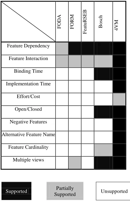
Finally, the table below shows how the 4VM measures against the identified requirements discussed in this chapter compared to existing feature modeling techniques.
The 4VM supports all the identified needs. The only two restrictions in the current version are: first, 4VM provides a fixed number of views (four views) for the feature model rather than unrestricted configurable multiple-views; and second, 4VM does not allow for complicated cost/benefit analyses on the feature model. These two issues are to be addressed in the future versions of the 4VM model and its toolset.
F
OD
A
F
ORM
F
ea
tu
RS
EB
Bo
sc
h
4
VM
Feature Dependency
Feature Interaction
Binding Time
Implementation Time
Effort/Cost
Open/Closed
Negative Features
Alternative Feature Name
Feature Cardinality
Multiple views
Supported Partially
[image:9.612.315.541.294.644.2]Supported Unsupported
5. Acknowledgement
We would like to thank Felix Bachmann and the SPL group at the SEI/CMU for their valuable input to this work during its initial stages in 2004. Also, we would like to thank Jaap van der Heijden, Chritiene Aarts and Bas Engel at the Software Architecture department, Philips Research Labs, Eindhoven, for their input and feedback on this work.
6. References
[1] K. C. Kang, S. G. Cohen, J. A. Hess, W. E. Novak, and A. S. Patterson, "Feature Oriented Domain Analysis (FODA) feasibility study," Software Engineering Institute, Carnegie Mellon University CMU/SEI-90-TR-21, 1990.
[2] J. Bosch, G. Florijn, D. Greefhorst, J. Kuusela, H. Obbink, and K. Pohl, "Variability Issues in Software Product Lines." In proceedings of the 4th International Workshop on Product Family Engineering, Berlin, Germany, 2002. pp. 13-21.
[3] F. Bachmann and L. Bass, "Managing Variability in Software Architecture." In proceedings of the ACM SIGSOFT Symposium on Software Reusability, May 2001. pp. 126-132.
[4] M. Svahnberg and J. Bosch, "Issues Concerning Variability in Software Product Lines." In proceedings of the Third International Workshop on Software Architectures for Product Families, 2000. pp. 146-157. [5] K. C. Kang, J. Lee, and P. Donohoe, "Feature-Oriented
Product Line Engineering," IEEE Software, vol. 19, pp. 58-65, July/August 2002.
[6] M. Griss, J. Favaro, and M. d'Alessandro, "Integrating Feature Modeling with the RSEB." In proceedings of the Fifth International Conference on Software Reuse, Vancouver, BC, Canada, June 1998. pp. 76-85.
[7] I. Jacobson, M. Griss, and P. Jonsson, Software Reuse - Architecture, Process and Organization for Business Success. New York: ACM Press, 1997.
[8] J. v. Gurp, J. Bosch, and M. Svahnberg, "On the Notion of Variability in Software Product Lines." In proceedings of the Working IEEE/IFIP Conference on Software Architecture (WICSA 2001), August 2001. pp. 45-54.
[9] "BigLever Software Gears,"
http://www.biglever.com/solution/product.html. [10] "Pure-Systems Pure::Variants,"
http://www.pure-systems.com/Variant_Management.49.0.html.
[11] R. Bashroush, I. Spence, P. Kilpatrick, and T. J. Brown, "A Real-time Network Emulator: ADLARS Case Study." In proceedings of the 3rd Asia Pacific International Symposium on Information Technology, Istanbul, Turkey, January 2004. pp. 610-618.
[12] T. Brown, R. Gawley, R. Bashroush, I. Spence, P. Kilpatrick, and C. Gillan, "Weaving Behavior into Feature Models for Embedded System Families." In proceedings of the 10th International Software Product Line Conference SPLC 2006, Baltimore, Maryland, USA, August 2006. pp. 52-64.
[13] R. J. A. Buhr and R. S. Casselman, Use Case Maps for object-oriented systems: Prentice Hall, 1996.
[14] R. Bashroush, T. J. Brown, I. Spence, and P. Kilpatrick, "ADLARS: An Architecture Description Language for Software Product Lines." In proceedings of the 29th Annual IEEE/NASA Software Engineering Workshop, Greenbelt, Maryland, USA, April 2005. pp. 163 - 173.