Iris Segmentation using Geodesic Active Contour for
Improved Texture Extraction in Recognition
Minal K. Pawar
P.G.Student,
Department of E & Tc,
Sinhgad College of Engineering,
Pune.
Sunita S. Lokhande
Asst. Professor, Department of
E & Tc,
Sinhgad College of Engineering,
Pune.
V. N. Bapat
GITM Jhajjav
ABSTRACT
Automatic identification/verification of a person through biometrics has been getting extensive attention due to an increasing importance of security. The most popular biometric authentication scheme employed for the last few years is Iris Recognition. The performance of iris recognition system highly depends on segmentation. For instance, even an effective feature extraction method would not be able to obtain useful information from an iris image that is not segmented accurately. The iris proposed recognition module consists of the preprocessing system, segmentation, feature extraction and recognition. Mainly it focuses on image segmentation using Geodesic Active Contours and comparison with traditional methods of segmentation. As active contours can 1) assume any shape and 2) segment multiple objects at the same time, they lessen some of the concerns related with conventional iris segmentation models. The iris texture is extracted in an iterative fashion by considering both local and global properties of the image. The matching accuracy of an iris recognition system is observed to improve upon application of the proposed segmentation algorithm. Experimental results on the CASIA (Institute of Automation, Chinese Academy of Sciences) Interval version3 iris databases implemented in MATLAB shows the efficiency of the proposed technique application.
General Terms
Pattern Recognition, Computer vision, Biometrics, Image processing.
Keywords
Iris recognition, iris segmentation, level sets, snakes, geodesic active contours (GACs), iriscodes.
1.
INTRODUCTION
Biometrics is the science which deals in identification of person based on his physiological and/or behavioral characteristics. The two categories of biometric identifiers include physiological and behavioral characteristics. Physiological characteristics are those which a person physically owns like fingerprints, iris patterns, face, ear shape, hand geometry, retina patterns, palm prints etc. and behavioral characteristics are the attitude of a person like gait, voice, signature etc. The requirements for a characteristic to be a biometric are universality, uniqueness, permanence and collectability. Applications of these systems include computer systems security, e-banking, credit card, access to buildings in a secure way.
Iris recognition is recognizing a person by analyzing random pattern of iris. Iris recognition is the most trustworthy method of person authentication due to unique textures,
non-invasiveness, and stability throughout the human life time, public acceptance, and availability of user friendly capturing Devices. The function of an iris recognition system is to extract, represent and compare the textural complexity present on the surface of the iris. Such a system comprises of iris segmentation, feature extraction (encoding) and feature matching.
Each algorithm of iris recognition system starts with iris segmentation. Iris segmentation is to locate the valid part of the iris for iris biometrics, including finding the pupillary and limbic boundaries of the iris, localizing its upper and lower eyelids if they occlude and detecting and excluding any superimposed occlusions of eyelashes, shadows or reflections. It is reported that most failures to match in iris recognition system result from inaccurate iris segmentation. So for the better performance of the iris recognition system correct segmentation method plays vital role.
2. RELATED WORK
filtering, Edge weighing according to position and curvature. Dobes et al.[14] has applied Canny edges detection, Angularconstrained Hough transform. Daugman et al.[6] uses active contours based on Fourier series and generalized coordinates.
Figure1: Block diagram of iris recognition system
The remainder of the paper is organized proposed system and baseline segmentation, encoding and matching method is described in Section 3. Section 4 provides an overview of the segmentation technique based on GACs. The matching performance due to this novel scheme is reported in Section 4. Section 5 concludes the paper.
3. IRIS RECOGNITION SYSTEM
Figure 1 is showing block diagram of an implemented iris recognition system, the basic blocks are as follows:
3.1 Iris Database
The database used for experimentation on the iris recognition system is CASIA Interval version3 database. It consists of total 2639 iris images of 249 subjects. The images were captured indoor mostly in two sessions with the resolution of 320*280.[23]
3.2. Pre-processing
The pre-processing is done before segmentation. Processing of the acquired iris image involves detection of specular reflections and the stage must remove noise and elements that can affect the feature extraction process. We used Gaussian filtering, and inpainting if specular reflections in the image is present.
3.3 Segmentation
The Geodesic Active Contours are used to segment the iris. To illustrate performance enhancement of recognition by using GAC technique, two other traditional methods viz., Integro-Differential Operator and Hough transform are also implemented.
3.3.1 Iris Segmentation Using Geodesic Active
Contour
The iris segmentation procedure using GAC can be divided mainly into two steps: 1.Pupil segmentation, and 2. Iris segmentation.
3.3.1.1 Pupil Segmentation
For the detection of the pupillary boundary, the eye image is first smoothed using a 2-D median filter. Then from that image minimum pixel (Min) value is determined. The iris is then binarized using a threshold value 30+ (Min). As predicted other than the pupil, other dark regions of the eye (e.g., eyelashes) are with less value than this threshold value. A 2-D median filter is then applied on the binary image to remove the comparatively smaller regions related with the eyelashes. Based on the median-filtered binary image, the exterior boundaries of all the remaining objects are traced.
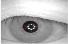
Generally, the largest boundary of the residual regions of the eye corresponds to the pupil. However, when the pupil is constricted, it is very likely that the boundary of the detected region corresponding to the eyelashes is larger than that of the pupil. But pupil cannot be considered as circle. So an ellipse fitting procedure is carried out on all detected regions. Finally, if the major and minor axes of the ellipse are same then as a result detected region will be circle in some cases. The area whose circumference contains the maximum number of black pixels is deemed to be the detected pupil. Sometimes, specular reflections can appear close to the boundary of the pupil that may confuse the pupil segmentation procedure. It is clear that the pupil is under-segmented due to the occurrence of the specular reflection near the pupil boundary. Hence, if specular reflection (bright spots in an image) is noticed in the neighborhood of the pupil, it is “inpainted” using the surrounding information. The final result of pupil segmentation is shown in the figure 2.
3.3.1.2
Iris Segmentation
For detection of the limbic boundary of the iris, method based on a level sets representation of the Geodesic active contour (GAC) model is used. This approach is based on the relation between active contours and the computation of geodesics (minimal length curves). The GAC scheme is contour evolution scheme based on image content and curve regularity.
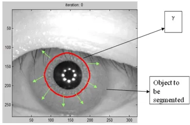
[image:2.595.357.499.615.707.2]The technique is to evolve the contour from inside the iris under the influence of geometric measures of the iris image. GACs combine the energy minimization approach of the classical “snakes” and the geometric active contours based on curve evolution. Evolution terminates when contour encounters the “boundary” of the object and able to detect boundary even if gaps exist in the boundary.GAC can split
Figure 2: Pupil Segmentation of image S1011L07 from CASIA interval version 3 database
Compare
Match Score
Decision Database
Iris Image Segmentation Normalization Feature
Extraction Pre-Processing
Iris Image Segmentation Normalization Feature
Figure 3: Curve
evolving towards the boundary of the object which is to be segmented.and merge at local minima.
Let (t) be the curve that has to gravitate toward the boundary of any object, at a particular time as shown in Figure 3. The time t is the iteration number. Let be a function defined as a signed distance function from the curve
) (t
.Thus,
(
x
,
y
)
distance of point (x,y) to the curve
(
t
)
. curve the outside is y) (x, if 0, curve the inside is y) (x, if , 0 curve the on is y) (x, if 0, ) , (x y
(1)
is of the same dimension as that of the image I(x,y )which is to is to be segmented. The curve
(
t
)
is a level set of the function
. Level sets are the set of all points in
where
some constant. Thus,
0: is the zeroth level set,
1: is the first level set and so on.
is the implicit representation of the curve
(t)and is called as the embedding function since it embeds the evolution of (t). The embedding function evolves under the influence of image gradients and regions characteristics so that the curve) (t
approaches the boundary of the object. [4][9]
Thus, instead of evolving the parametric curve
(t) (e.g.,the Lagrangian approach used in snakes), the embedding function itself is evolved. For the implementation, the initial curve)
(
t
is assumed to be a circle of radius r just beyond the pupillary boundary. Let the curve (t) be the zeroth-level set of the embedding function. This implies that,. 0
dt
d
The evolution equation for
t such that
(
t
)
remains the zeroth level set is given by,
t(
c
)
(2)where, K the stopping term for the evolution, is an image dependant force and is used to decelerate the evolution near the boundaries; c is the velocity of the evolution;
indicatesthe degree of smoothness of the level sets; and
is the curvature of the level sets computed as,2 3 2 2 ) ( 2 2 2 y x yy xy y x
xx y x
(3)
Where
x is the gradient of the image in the x direction; y
is the gradient in the y direction;
xxis the second ordergradient in the x direction;
yy is the second order gradient in the y direction;
xy is the second order gradient first in the x direction and then in the y direction. Equation (4) is the level set representation of geodesic active contour model. This means that the level set C of
is evolving according to the equation,
c
N
N
N
C
t
(4)where, N is the normal to the curve. The first term
)
(
N
provides the smoothing constraints on the level sets by reducing the total curvature of the level sets. The second term
cN
acts like a balloon force and it pushes the curve outward towards the object boundary.The goal of stopping function is to slow down the evolution when it reaches the boundaries. However, the evolution of the curve will terminate only when K=0, i.e., near an ideal edge. In most images gradient values will be different along the edge, thus necessitating different K values. In order to circumvent this issue, the third geodesic term
N
is necessary so that the curve is attracted towards the boundaries (
points toward the middle of the boundary).This term makes it possible to terminate the evolution process even if (a) the stopping function has different values along the edges, and (b) gaps are present in stopping function. The stopping term used for the evolution of level sets is given by, )) , ( ) , ( ( 1 1 ) , ( y x I y x G y
x (5)
Where, I(x,y) is the iris image and κ and α are constants. As from the equation it can be seen that K(x,y) is not a function of t. In the implementation the obtained stopping function is shown in the figure 4. [k=1.8,α=8]
Figure 4: Stopping Function (K) of image S1011L07 from CASIA interval version 3 database
(a)
(b)
(c)
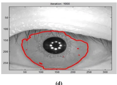
[image:4.595.72.261.71.197.2](d)
Figure 5: Evolution of the GAC during iris segmentation. (image S1011L07 from CASIA interval version3 database)
(a) Iris image with initial contour ( Zeroth level set ). (b) Mesh plot of the signed distance function
.(X and Y axis correspond to the size of the iris image and the Z axisrepresents different level sets). (c) Contours after 250 iterations, (d)Final Contour after 1000 iterations.
and the embedding function,
, over the image domain is initialized to a signed distance function from
(t0)which looks like a cone. Discretizing equation (2) leads to the following expression:
tj i t
j i t t
j i j i t j i t
j i t
j i
c t
' , , ,
' , '
, , 1
,
(6)
Where, tis the time step. (
t
=0.05). The firstterm t
j i
c',
on the right hand side of the aboveequation is the velocity term (advection term) and in case of the limbic boundary segmentation, acts as an inflation force. The second term
t t
j i j
i
, , is curvature based
smoothing term and can be discretized using central differences. (c=1 and
1
for all iris images).The thirdgeodesic term t
j i t
j i, ,
is also discretized using the central differences.
One important feature of GACs is their ability to handle “splitting and merging” boundaries. This is especially important in the case of iris segmentation since the radial fibers may be thick in some portions of the iris, or the crypts present in the ciliary region may be unusually dark, leading to prominent edges in the stopping function as shown in figure 3. If the segmentation technique is based on parametric curves, then the evolution of the curve might terminate at these local minima. However, GACs are able to split at such local minima and merge again. Thus, they are able to effectively deal with the problems of local minima thereby ensuring that the final contour corresponds to the true iris boundary. The stopping criterion for the evolution of GACs is image independent and does not take into account the amount of edge details present in an image. Thus, if the iris edge details are weak, the contour evolution may not stop at the desired iris boundary leading to an over segmentation of the iris. Over segmentation can be avoided by developing an adaptive stopping criterion for the evolution of the GACs.[4]
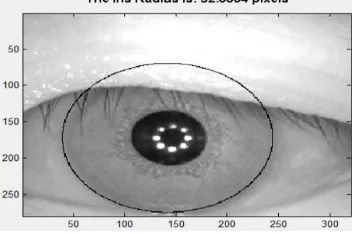
[image:5.595.90.269.341.458.2]The extracted contour is used to create the binary mask that is used for the matching of the iriscodes (3.6). To normalize the iris and convert it to a rectangular entity, its radius and the corresponding center coordinates have to be estimated. If the occlusion due to the upper or lower eyelids is large, then a circle that fits all the points on the extracted
Figure 6: Accurate estimation of radius of image S1011L07 from CASIA interval version 3 database
contour will lie within the actual boundary of the iris. Thus, only those points on the contour lying on the boundary of the iris and sclera (as opposite to the iris and the eyelids) should be used to estimate the radius and center of the iris. To make sure this, six points at angles of [-30°,0°,30°,150°,180°,210°] with respect to the horizontal axis are chosen from the extracted contour and their mean distance from the center of the pupil is calculated. This value is used as the approximate radius (R) of the iris . A circle is next fitted through all the points on the contour that are within a distance of R±10 pixels from the center of the pupil. The center and radius of such a circle is the center (x,y) and the radius R of the iris. [4] Figure 6 illustrates the estimated radius by this approach.
3.3.2. Daugman’s Integro Differential Algorithm
The best known and thoroughly examined iris segmentation method is Daugman et.al.[21] method using Integro differential operators, which are a variant of the Hough Transform, which act as circular edge detectors and have been used to determine the inner and the outer boundaries of the iris. They also have been used to determine the elliptical boundaries of the lower and the upper eyelids. An integro differential operator can be defined as:
0 0 0
0,y ) r,x ,y x
(r,
ds
r
y
x
I
r
r
G
2
)
,
(
)
(
max
(7)where, I(x,y) is the image, the operator search over the image domain I(x,y) for the maximum in the blurred derivative with respect to increasing radius r, of the normalized contour integral of I(x,y) along a circular arc ds of radius r and center ( x0 ,y0). The symbol * donates convolution and G(r) is a
Gaussian filter used as a smoothing function. It is obvious that the results are inner and outer boundaries of iris. First, the inner boundary is localized, due to the significant contrast between iris and pupil regions. Then, outer boundary is detected, using the same operator with different radius and parameters. The eyelids can be detected in a similar fashion by performing the integration over an elliptical boundary rather than a circular one. [21]
Since the operator works with raw derivative information, it does not suffer from the thresholding problems of the Hough transform. However, the algorithm can fail where there is noise in the eye image, such as from reflections, since it works only on a local scale. This acts as a limitation of the operator. [19]
3.3.3. Hough Transform
The circular Hough transform can be employed to decide the radius and centre coordinates of the pupil and iris regions. Firstly, an edge map is generated by calculating the first derivatives of intensity values in an eye image and then thresholding the result. From the edge map, votes are cast in Hough space for the parameters of circles passing through each edge point. These parameters are the centre coordinates x
c
and y
c
, and the radius r, which are able to define any circle according to the equation (8),
0
2 2
2
r
y
x
c c (8)A maximum point in the Hough space will correspond to the radius and centre coordinates of the circle best defined by the edge points. Wildes et al. and Kong and Zhang et al. also make use of the parabolic Hough transform to detect the eyelids, approximating the upper and lower eyelids with parabolic arcs, which are represented as equation (9),
x hj sinj y kjcosj
aj
x hj
cosj
y kj
sinj
2
(9)
where, aj controls the curvature, (hj, kj) is the peak of the
parabola and θj is the angle of rotation relative to the x-axis.
There are a number of problems with the Hough transform method. First of all, it requires threshold values to be chosen for edge detection, and this may result in critical edge points being removed, resulting in failure to detect circles/arcs. Secondly, the Hough transform is computationally intensive due to its „brute-force‟ approach, and thus may not be suitable for real time applications.
Both of Daugman & Wilds systems make use of first derivatives of image intensity to signal the location of edges that correspond to the borders of the iris.[19]
3.4. Normalization
Iris segmentation is followed by a normalization generate a fixed dimension feature vector that provide itself to matching. The rubber sheet model proposed by Daugman maps each point in the (x, y) domain to a pair of polar coordinates (r,θ). This results in a fixed size unwrapped rectangular iris image.
3.5. Feature Extraction
For accurate recognition result, the most discriminating information present in an iris pattern must be extracted. Only the significant features of the iris must be encoded so that comparisons between iris can be made. Log Gabor filters are then used to extract the textural information (encoding) from the unwrapped iris.
A disadvantage of the Gabor filter is that the even symmetric filter will have a DC component whenever the bandwidth is larger than one octave. However, zero DC component can be obtained for any bandwidth by using a Gabor filter which is Gaussian on a logarithmic scale, this is known as the Log-Gabor filter. The frequency response of a Log-Log-Gabor filter is given as:
2
0 2
0
]
2
[log
]
[log
exp
)
(
f
f
f
f
G
(10)Where, f
0
represents the centre frequency, and σ gives the bandwidth of the filter. [19]
3.6. Matching Algorithms
The feature vectors are compared using a similarity measure for which matching algorithms are used. Let I1 and I2be the
two iris codes to be compared, and M1 and M2 be their
respective masks. The Hamming distance (HD) is calculated:
2 1
2 1 2
1
M M
M M I
I HD
(11)
where the XOR operator,
, detects the disagreement between the corresponding bits in the iris codes, the AND operator,
,ensures that the Hamming distance is calculated using only the bits generated from the true iris region and the operator
computes the norm of the bit vector. Ideally, the Hamming distance between two images of the same iris will be 0 corresponds to genuine score.4. RESULTS
The matching performance of the implemented GAC segmentation scheme and traditional Daugman integrodifferential operator & Masek Hough transform is evaluated on the CASIA interval version3 database in MATLAB 2010a (Intel core3 processor).
Performance evaluation parameters used for the evaluation of the recognition system are False Acceptance rate (FAR) and False Rejection Rate (FRR). Using these two parameters the plot of Receiver Operating Characteristic (ROC) is obtained as illustrated in figure 8.From the accuracy of recognition, the performance of the integro-differential operator segmentation is poor compared to Masek‟s method and the GAC technique which is shown in Table 5.3
The accurate estimation of radius by GAC method is shown in figure 7. It is compared with the integro differential operator and hough transform.
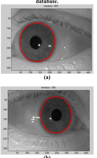
[image:6.595.310.544.150.638.2]It must be noted that the GAC technique used for segmenting the iris is suitable for operating on the iris images of different databases (CASIA V3, WVU nonideal, etc.) The accurate segmentation results of the non ideal eye imagesfrom WVU
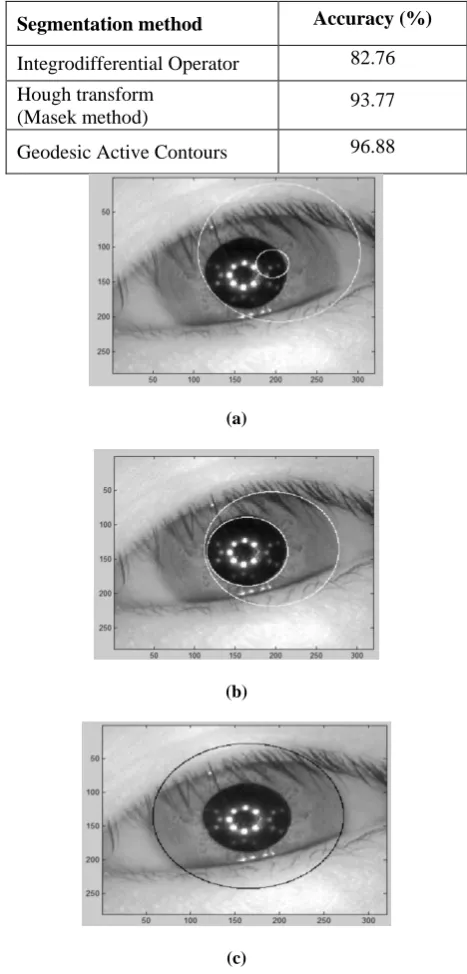
Table 5.3: Accuracy of recognition using each segmentation method for CASIA-Interval-3 database.
Segmentation method
Accuracy (%)
Integrodifferential Operator
82.76
Hough transform
(Masek method)
93.77
Geodesic Active Contours
96.88
(a)
(b)
(c)
Figure 7: Radius obtained from segmented output on S1144L02 image from CASIA interval V3 database (a)
Integro differential operator, (b) Masek’s method,(c) Geodesic active contour
Figure 8: Receiver Operating Characteristic of all three segmentation methods on the CASIA interval version3 iris
database.
(a)
(b)
Figure 9: Segmentation result on the images of WVU off-angle database irides using GAC: (a) Image 1_1, (b) Image
19_2
Thus, GAC scheme which is an evolution process used to extract the limbic boundary of the iris as well as the contour of the eyelid for separating iris texture from its surroundings.
5. CONCLUSION
The process of segmenting the iris plays a vital role in iris recognition systems. In this paper, GAC technique for iris segmentation is presented. The comparisons of experimental results on the CASIA interval version3 dataset indicate the benefits of the GAC over the Daugman‟s integro differential operator and Masek‟s Hough transform. The GAC algorithm also supports in accurately estimating the radius of the iris and its center. As active contours can assume any shape and can segment multiple objects simultaneously, the GAC approach lessens some of the concerns related with the traditional models. The stopping criterion for the evolution of GACs is image independent and does not take into account the amount of edge details present in an image. Thus, if the iris edge
details are weak, the contour evolution may not stop at the desired iris boundary leading to an inaccurate segmentation. The time required to segment the iris using GAC is more though it gives more accuracy.
7. REFERENCES
[1] B.Chouhan & S.Shukla, “Comparative Analysis Of Robust Iris Recognition System Using Log Gabor Wavelet And Laplacian Of Gaussian Filter,” International Journal of Computer Science & Communication (IJCSC),Vol.2, No.1, pp. 239-242,Jan-Jun2011.
[2] Hugo Proenca, “Iris Recognition: On the Segmentation of Degraded Images Acquired in the Visible Wavelength”, IEEE Transactions On Pattern Analysis And Machine Intelligence, Vol. 32, No. 8, August 2010. [3] Ann A. Jarjes, Kuanquan Wang, Ghassan J. Mohammed,
“Iris Localization: Detecting Accurate Pupil Contour and Localizing Limbus Boundary”, 2nd International Asia Conference on Informatics in Control, Automation and Robotics,978-1-4244-5194,Apr-2010
[4] S.Shah & A. Ross, “Iris Segmentation Using Geodesic Active Contours”, IEEE Transactions on Information Forensics And Security,Vol.4, No.4, pp.824-836, Dec2009.
[5] Kevin W. Bowyer, Karen Hollingsworth, Patrick J. Flynn, “Image understanding for iris biometrics: A survey”, Computer Vision and Image Understanding, Elsevier, 110 281–307, 2008.
[6] J. Daugman, “New methods in iris recognition,” IEEE Trans. Syst.,Man, Cybern., vol. 37, no. 5, pt. B, pp. 1167–1175, 2007.
[7] Abhyankar A, Schuckers S., “Active shape models for effective iris segmentation,” In: Proceedings of the SPIE Conference on biometric technology and human identification Orlando, FL.p. 62020H.1–10. , 2006. [8] J.Zuo, N.Kalka, & N. Schmid, “A Robust Iris
Segmentation Procedure for Unconstrained Subject Presentation,” Proc. Biometric Consortium Conf., pp.1-6, 2006.
[9] A.Ross and S. Shah, “Segmenting Non-Ideal Irises Using Geodesic Active Contours,” Proc. IEEE 2006 Biometric Symp., pp. 1-6, 2006.
[10]L.R. Kennell, R.W. Ives, and R.M. Gaunt, “Binary Morphology and Local Statistics Applied to Iris Segmentation for Recognition,” Proc. IEEE Int‟l Conf. [11]Image Processing, pp. 293-296, Oct. 2006.
[12]H. Proenca and L.A. Alexandre, “Iris Segmentation Methodology for Non-Cooperative Iris Recognition,” Proc. IEEE Vision, Image, & Signal Processing, vol.153, no. 2, pp. 199-205, 2006.
[13]E. Arvacheh and H. Tizhoosh, “A Study on Segmentation and Normalization for Iris Recognition,” MSc dissertation, Univ. of Waterloo, 2006.
[image:7.595.91.247.279.533.2][15]M. Dobes, J. Martineka, D.S.Z. Dobes, and J. Pospisil, “Human Eye Localization Using the Modified Hough Transform,” Optik, vol. 117, pp. 468-473, 2006.
[16]V. Caselles, R. Kimmel, and G. Sapiro, “Geodesic active contours,” Int. J. Comput. Vision, vol. 22, no. 1, pp. 61– 79, Feb./Mar. 1997.
[17]Z. Zheng, J. Yang, and L. Yang, “A Robust Method for Eye Features Extraction on Color Image,” Pattern Recognition Letters, vol. 26, pp. 2252- 2261,2005. [18]Ma L, Tan T, Wang Y, Zhang D., “Efficient iris
recognition by characterizing key local variations”, IEEE Trans Image Process; 13:739–50, 2004.
[19]Ma L, Tan T, Wang Y, Zhang D., “Personal identification based on iris texture analysis”, IEEE Trans Pattern Anal Machine Intell; 25:1519–33,2003.
[20]L. Masek, “Recognition of Human Iris Patterns for Biometric Identification”, M.S. Dissertation, The University of Western Australia, 2003.
[21]Wildes R.P., “Iris recognition: an emerging biometric technology”, Proc. of IEEE, Vol.85, No. 9, September 1997.
[22]J. Daugman, “High confidence visual recognition of persons by a test of statistical independence,” IEEE Trans. Pattern vol. 15, no. 11, pp. 1148–1161, Nov. 1993.