25
A Framework for Enterprise Mashups
Architectural Patterns
Ossama M. Rashed
Department of Computer Science, Faculty of Computers and Information, Cairo University, Egypt
Amr Kamel
Department of Computer Science, Faculty of Computers and Information, Cairo University, Egypt
ABSTRACT
Web 2.0 has introduced some new technologies and concepts in the web development arena. Based on the objectives of building situational, agile, efficient, variant, and low-cost web applications, the idea of Mashups has evolved. The business need to reduce the cost of building new, small-to-medium-size applications that may not be durable to the extent that justifies the high cost of building traditional web applications has emphasized the Mashups direction.
Mashups focus on what is widely called “Long Tail” which represents the 80% of the applications that affect 20% of the users as opposed to the traditional enterprise applications as shown in Figure 1 below:
In mashups, given a set of mashups building blocks (e.g., widgets), a large number of situational applications may be composed with little or no coding effort to serve certain business need. It is to be noted that this paper deals with enterprise mashups (that are data-centric) rather than user mashups (that are visual-centric).
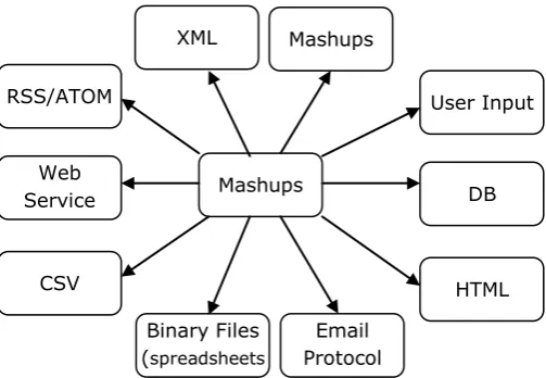
An important feature in enterprise mashup is its ability to “mash up” data from different sources. These sources may include XML, HTML, Web Services, RSS, and others. Figure 2 depicts different data sources that can be mashed up together.
Moreover, existing mashups can be utilized to result into new mashups that provide a completely-new mashups. This trend allows for a better agility and response time for business demands.
Because the process of assembling mashups is repetitive, standardizing or formalizing this process would save much effort and time for further assembly processes and would ensure better final results as well. This paper defines a pattern structure to be followed by those contributing to standardizing the process of mashup assembly. Moreover, it provides a sample mashup design pattern that would clearly realize this concept.
General Terms
Web 2.0, Software Engineering, Web Development
Keywords
Mashup, Web 2.0, Architectural Patterns, Design Patterns, Widgets
1.
INTRODUCTION
ProgrammableWeb.com lists slightly less than 7000 mashups with around 3 mashups being added each day. There are more than 327,873 published widgets and counting daily. The decision of when to use which of them to assemble a new mashup becomes significantly difficult. Moreover, it is not an easy task to define how those selected widgets are orchestrated together to give the wished result.
Software industry has witnessed a very important, and useful, concept called “Design Patterns”. This concept was first adapted to patternzie Object-Oriented common problems along with their solutions and conditions especially for desktop and enterprise applications. Thanks to OO Design mashupsApplica
tions Users
Mashups Area
80% of the applications serving 20% of the users
Traditional Enterprise Applications Area
20% of the applications serving 80% of the users
Figure 1: Long tail graph showing Mashups area of interest
Mashups
User Input
DB
HTML
Email Protocol Binary Files
(spreadsheets
) CSV
Web Service RSS/ATOM
[image:1.595.308.560.208.382.2]Mashups XML
patterns, many problems were solved saving time and effort with satisfactory results.
The same concept of patternization is still valid to be applied to the Mashups development. The reason behind the need to have separate design/architecture patterns to mashups that differs from traditional design patterns is the nature of mashups. The main characteristics that distinguish mashups are:
1. In most cases, mashups are meant to be developed by non-technical people (e.g., business users and administrators). Hence, there’s a need to define not only the technical value of the pattern, but also the business value. Such determination doesn’t exist in traditional design patterns
2. Mashup building blocks are smaller web modules (e.g., widgets, portlets, gadgets …etc.) while classes and methods are their counterpart in OO design. This means that traditional OO design patterns would not fit in this case
3. In mashups, the main focus in put on the definition of how the small building blocks are assembled together to create a mashup. No great attention is paid to the programming language in which they are written nor the number of methods contained in each class
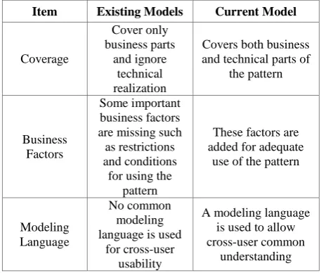
[image:2.595.47.276.441.635.2]Some efforts were exerted in this area; however, they lack some important features. The table below describes the main differences between this framework and existing efforts in Mashup Paterns:
Table 1. Differences between this model and existing ones Item Existing Models Current Model
Coverage Cover only business parts and ignore technical realization
Covers both business and technical parts of
the pattern
Business Factors
Some important business factors are missing such as restrictions and conditions
for using the pattern
These factors are added for adequate
use of the pattern
Modeling Language
No common modeling language is used
for cross-user usability
A modeling language is used to allow cross-user common
understanding
Throughout this paper, the mashup building block will be referred to as widget for simplicity although it can be any other component (portlet, gadget …etc.)
In this paper, will start by listing the core widgets, then define the structure for a pattern that specifies how these widgets may fit together to represent that pattern, and finally will give an illustrative use case.
2.
CORE WIDGETS
As discussed earlier, widgets are the building blocks of the mashup. There are core widgets that may be used in
composing a mashup. These core widgets include, but not are limited to:
Fetch
This widget type is used to fetch/retrieve date from a certain data source. It can also be used to unlock data from a closed source (e.g., department attendance excel sheet). Usually, such widgets are placed at the beginning of the Mashup structure and other widget types follow. This type includes the following widgets:
o XML fetch: Fetching XML documents and feeds including RSS & Atom feeds and other XML-based documents.
o HTML fetch: Used to crawl and parse web pages and extract some information from within web pages (HTML parsing and String manipulation) o Other structured data (e.g., CSV)
o API (google maps, google docs …etc.)
o DB
o Web Service
Filter
o XML Filter: A filter widget that takes, as an input, XML document and filters it based on a certain criteria and returns the resultant XML o String Filter: A filter widget that uses Regular
Expressions to filter an incoming stream and returns the resultant string
Transform
o A transformation from a particular data type or format to another one based on predefined rules. Process
o Combine: combines input from different sources o Logical operations: applies logical operators (e.g.,
less than, equal, …etc.) on input and returns the result
o Business rule(s): applies some business rules depending on the nature of the mashup purpose. Input
o User Input: a widget that takes input from user. This input can be in any format (e.g., text, file, URL …etc.)
Output
o Formatted output: Text-based output including all text formats (e.g., RSS, String, date, numbers …etc.)
o Dashboard output: Graph-based output including all types of dashboards (e.g., bar charts, pie charts, meter chart …etc.)
27 Other widgets and/or widget categories may be added by
other contributors from the mashup development community as new widgets come up.
3.
PATTERN STRUCTURE
FRAMEWORK
In this section, the mashup pattern structure will be defined. New efforts to develop mashup patterns may follow this structure to define these new patterns in order to have a unified view of what a mashup is. Besides, this will allow a better experience exchange. Below is the framework definition.
3.1
Problem
A problem definition including the business need and challenges. The required objective should be clear, specific and measurable.
3.2
Solution (Pattern Definition)
This section should highlight how different widgets are assembled together to address the mentioned problem. All details that are important to the adoption of this particular solution should be pointed out
3.3
Pattern Name
This section determines the pattern name. This name should be short (one or two words maximum), meaningful and unique.
3.4
Contributing Widgets
Widgets that contribute in the assembly of this particular mashup should be listed here
3.5
Conditions
This section describes conditions and constraints enforced on this pattern. In some cases, this pattern should not be used in certain domains and/or under certain conditions depending on the nature of the pattern and the nature of the domain this pattern to be used in as well
3.6
Mashup Modeling Language (MML)
It is very common to represent different software designs using diagrams. These diagrams provide a unified language among different software engineers and other stakeholders. Among these diagrams is the flowchart diagram that can be used in both technical and business areas. Mashup Modeling Language (Flowchart-like diagram) will be used to represent the design of mashup patterns.Each block in the diagram will represent a single widget performing a certain task. Widgets participating in this diagram are extracted from the core widgets illustrated earlier. Mashup Modeling Language (MML) consists of the following building blocks:
3.6.1
Fetch Widgets
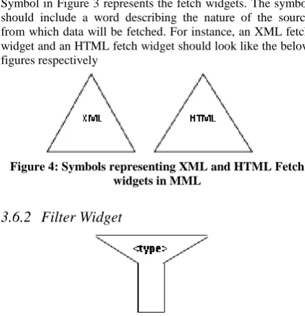
Symbol in Figure 3 represents the fetch widgets. The symbol should include a word describing the nature of the source from which data will be fetched. For instance, an XML fetch widget and an HTML fetch widget should look like the below figures respectively
3.6.2
Filter Widget
This symbol represents the filter widgets. As with fetch widgets, a string should be added to indicate the filter type (XML or String)
3.6.3
Process Widget
This symbol indicates a process widget. It’s clear that this symbol is semantically the same as used in normal flowchart process. Again, the process widget type should be written inside the process symbol.
3.6.4
Process Widget
This symbol indicates an input. There’s no need to define the input type as it would always refer to a user input.
3.6.5
Transform Widget
[image:3.595.315.537.75.305.2]This symbol refers to a transformation widget that takes, as an input, a certain data format and transfers it to another format based on predefined rules. Source Data format should be Figure 3: Symbol used to represent Fetch widget in MML
Figure 4: Symbols representing XML and HTML Fetch widgets in MML
Figure 5: Symbol used to represent Filter widget in MML
Figure 6: Symbol used to represent process widget in MML
[image:3.595.386.463.387.449.2]Figure 7: Symbol used to represent input widget in MML
[image:3.595.366.524.653.705.2]indicated on the left arrow and the destination should be indicated on the right arrow.
3.6.6
Output Widget
This symbol represents an output widget. Output type should be clearly identified on the symbol (e.g., Dashboard, report …etc.)
4.
CASE STUDY
4.1
Problem
An enterprise wants to get daily updates on its main competitor in the market. Originally, the enterprise assigned some personnel to track the competitor’s news from different websites/feeds. These personnel browse several websites, read the news and write a report. This process; however, is time and effort consuming and, most importantly, error prone. The enterprise management then decided to automate this whole process through utilizing available information sources in a mashup.
4.2
Solution (Pattern Definition)
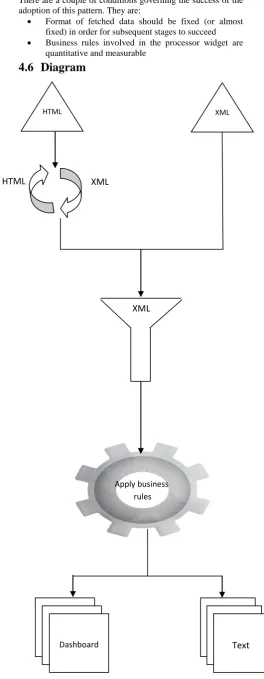
The mashup that addresses this problem should initially contain a widget that fetches data from different sources (stock feed, competitor enterprise’s RSS, and news portals). However, not all fetched data will be included in the final report, so there will be a need to develop a filter widget to exclude irrelevant data.
Filtered data are not necessarily formatted in the same format (XML,HTML …etc.). Hence, these data are subject to a transformer widget that would transfer all data structures to a unified structure (XML). The next step is to process these filtered and transformed data using a processor widget. The aim of using this widget is to apply business rules on these data. These business rules may include as many and fine grained business details as the enterprise needs. However, using only basic rules and indicators may be more accurate in some cases. Examples for business rules include the calculation of the change percent in the competitor enterprise share in the stock.
Finally, an output widget is used to display the report in a certain format. In this case, the report may include a graph representing the curve of the share price in the stock as well as text-based indicators (e.g., the competitor has acquired Company X for Y$)
4.3
Pattern Name
Competitor Analyzer Pattern4.4
Contributing Widgets
Fetch data from enterprise’s RSS feed, news portals, stock feed, and chamber of commerce periodical Filter unwanted data and ignore it
Transform fetched data into a single data structure (e.g., XML)
Process remaining data by applying business rules (example: IF data contains X DO Y )
Output result
4.5
Conditions
There are a couple of conditions governing the success of the adoption of this pattern. They are:
Format of fetched data should be fixed (or almost fixed) in order for subsequent stages to succeed Business rules involved in the processor widget are
quantitative and measurable
4.6
Diagram
Figure 9: Symbol used to represent output widget in MML
HTML
HTML XML
XML
Apply business rules
Dashboard Text
[image:4.595.297.562.91.772.2]29
5.
Conclusion
In this paper, a discussion was made on how enterprise mashups can be patternized for a better common understanding and knowledge exchange in the mashups development. Then, the paper went through defining the model to be followed in defining new mashup design patterns, and came with a case study illustrating the concept in more practical details.
Besides, the Mashup Modeling Language was discussed in details and covered in the use case defining how different widgets may cooperate to result in a certain-purpose mashup.
6.
ACKNOWLEDGMENTS
Thanks to my wife Sara, my parents and Dr. Amr Kamel for their continuous support and help
7.
REFERENCES
[1] Enterprise Mashups why do I care? Ross Mason. [2] Statistical Data as a Service and Internet Mashups by
Zoltan Nagy. Seminar on Emerging Trends in Data Communication and Dissemination, United Nations. [3] The Business Case for Enterprise Mashups. Nicole
Carrier, Tom Deutsch, Chris Gruber, Mark Heid, Lisa Lucadamo Jarrett
[4] Mashup Patterns, Michael Ogrinz