© 2018, IRJET | Impact Factor value: 6.171 | ISO 9001:2008 Certified Journal | Page 2819
Automatic Center Stand For Motorcycle
Aakarsh B S
1, Guntumadugu Girish Raj
2, Lakshmisha H M
3, Likhith H M
4, Dr. T. Madhusudhan
51,2,3,4
UG Students at SJBIT, Bengaluru, Karnataka, India
5
Dr.T.Madhusudhan: Head of Department, Department of Mechanical engineering, SJBIT,
Bengaluru, Karnataka, India
---***---Abstract -
Conventionally two components are used forstanding the motorcycle, namely side stand and center stand. Both components undergo static loading. The side stand is easily deployed allowing the motorcycle to lean to the left side. The task of mounting two wheelers on the center stand can be challenging. To operate center stand, rider has to get down from bike and has to pull against the lever which is difficult sometime. Rider has to lift minimum 50% of weight of motorcycle to engage the center stand. It becomes more difficult in case of heavy two wheelers like the Royal Enfield or if the rider is old. In this paper, an automated centre stand is designed and fabricated which uses a linear actuator powered by a battery to lower the stand and lift the vehicle and park it on the stand. This stand minimises human efforts to almost zero. In addition, the self-balancing mechanism was firmly established which lifts the motorcycle upright on uneven surfaces. As a result, it has become possible to install this automated centre stand in mass production scooter.
Key Words- Center stand, linear actuator, key operated, battery, DPDT switch, spur gear, etc
1. INTRODUCTION
In modern developing world, automobile plays important role especially two wheelers because it saves the time of traveller by reaching the target place very faster. Two wheelers refer vehicles that run on two wheels. India is the second largest producer of two wheeler and stand next to China and Japan in terms of production. Now a day’s there are thousands of bikes running on the road. In densely populated area, parking of two wheeler is main problem. Since every individual use side stand rather than center stand.
A center stand is a device on a bicycle or motorcycle that allows the bike to be kept upright without leaning against another object or the aid of a person. High-speed racing motor bikes have only center stand.
1.1 Advantage of Center Stand Over Side Stand
The side stand although easy makes the bike rest on three points of contacts namely: The Front and rear wheel and the stand. The Front and rear wheel experience almost equal amount of force of the bike`s Weight but the side stand experiences a greater force. The bike is however tilted in this position makes it difficult to do some repair or inspection work on the tilted side. On the central stand the bike entirely lays on the stand and just touches either of front or rear tyre with almost no force.
Using a side stand would make the load acting on bearings and other pivotal points in an angular manner that it might cause slight misalignment in long term use which might affect the performance of bike.
When we are filling air in our tyres we cannot check it by hand as in bicycle tyres. We need proper pressure gauge. But using pressure gauge will provide different results when the bike tyre is in side stand as contact pressure(remember three point contact) along with air pressure will provide wrong reading. Using a center stand will put almost zero force on tyres which will get accurate readings.
1.3 Problem Identification
On surveying, it was found that around 72% males and 28% females drive scooters. Among those 72% males, around 20% are oldies and remaining are adults. Mostly females and old people find it difficult to apply centre stand and hence this made us develop and make it automated. Moreover, applying a side stand;
1. Develops fatigue in stand.
2. Increases chances of accident.
3. Requires more parking spaces.
4. Reduces battery life since the electrolyte is in constant touch with electrode. [2]
1.4 Solution For Above Problems
The automated center stand is fixed at the same location for that of the conventional stand. It has two main parts; the lower unit and the upper unit. The upper unit is pivoted to the motorcycle frame and the lower unit is joined to a curved surface for easy lifting. The linear actuator is powered by automobile battery, controlled by toggle DPDT switch which changes the polarities of the supply. The linear actuator is pivoted to the stand assembly which distributes load equally on both the limbs of the stand.
2. MAIN COMPONENTS OF PROJECT
1) DC motor 2) Spur gear
© 2018, IRJET | Impact Factor value: 6.171 | ISO 9001:2008 Certified Journal | Page 2820 2.1 Component Specification
2.1.1 DC motor
A DC motor is a class of rotary electrical machines that converts direct current electrical energy into mechanical energy. Nearly all types of DC motors have some internal mechanism, either electromechanical or electronic, to periodically change the direction of current flow in part of the motor. A DC motor's speed can be controlled over a wide range, using either a variable supply voltage or by changing the strength of current in its field windings. The most common type of motor is a 12V DC motor. It is small and inexpensive, yet powerful enough to be used for many applications. One characteristics of a 12V DC is the operating voltage.
Fig 1: DC Motor
2.1.2 Spur Gear
Spur gears or straight-cut gears are the simplest type of gear. They consist of a cylinder or disk with teeth projecting radially. The teeth are mainly involute but less commonly cycloid. The edge of each tooth is straight and aligned parallel to the axis of rotation. These gears mesh together correctly only if fitted to parallel shafts. No axial thrust is created by the tooth loads. Spur gears are excellent at moderate speeds but tend to be noisy at high speeds. Here we have used spur gear which has required gear ratio to obtain the required rpm to drive rod. Gears are generally made from metallic materials to have sufficient strength and properties. Here we have used 48 teeth and 12 teeth spur gear.
Fig 2: Spur Gear
2.1.3 Linear Actuator Housing
Attaching a motor to an electric linear actuator requires an adaptor or housing. The mounting hardware needed varies based on motor type and brand as well as on how the motor is to be mounted either inline or reverse parallel. An inline configuration directly couples the motor’s driving shaft to the actuator through housing. This configuration provides excellent motor support and allows maximum power transmission from the motor to the actuator. We have used parallel housing.
2.1.4 Key Operated Switch
A key switch (sometimes called a lock switch) is a switch that can be activated only by the use of a key. They are usually used in situations where access needs to be restricted to the switch's functions. Key operated switch is mainly used for security and safety purpose. It operates as that of a conventional switch with rotary action. It can be activated only by using a key. Different types of key switches are available on the bases of ampere rating. The main advantage of using key operatedswitch instead of normal switch is to avoid accidental application of normal switch while riding the vehicle. It also covers child safety and operation by unskilled users.[3]
Fig 3: Key Switch
2.1.5 DPDT Switch
A switch is an electrical component that can "make" or "break" an electrical circuit, interrupting the current or diverting it from one conductor to another. The mechanism of a switch removes or restores the conducting path in a circuit when it is operated.
DPDT stands for double pole double throw switch. This is a dual ON/OFF switch consisting of two on position. It has six terminals, two are input contacts and remaining four are the output contacts. Two input contacts are connected to one set of output contacts in one position and in another position, input contacts are connected to the other set of output contacts.[5]
Fig 4: DPDT switch
2.1.6 Battery
lead-© 2018, IRJET | Impact Factor value: 6.171 | ISO 9001:2008 Certified Journal | Page 2821 acid type, using six series-connected cells to provide a
nominal 12 volt system.Despite having a very low energy-to-weight ratio and a low energy-to-volume ratio, its ability to supply high surge currents means that the cells have a relatively large power-to-weight ratio. These features, along with their low cost, make them attractive for use in motor vehicles to provide the high current. As they are inexpensive compared to newer technologies, lead–acid batteries are widely used.
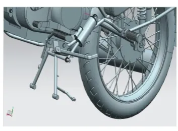
3. DESIGN AND CALCULATION
Fig 5: Assembled View of Center Stand With Linear Actuator
3.1 Design of Spur Gear
Power input = Pin = Voltage*current=V*I = 12*3.8 = 33.6W
Power output= Pout = Force*velocity=F*v =1000N*16.6mm/sec Assume α= 200 Full Depth Involute
3.1.1 Identification of Weaker Member
Both gear and pinion is made of same material i.e. cast iron
From design data hand book table 23.10 ∴𝞼o = 55 MPa
Since gear and pinion is made of same material, ∴ Pinion is a weaker member .
From design data hand book table 23.6 Assume Z1 = 12
Hence from lewis equation for bending
y1 = 0.154 – = 0.078
3.1.2 Tangential tooth load
Ft1 =
Where n = speed of weaker member
r = radius of weaker member ∴ r1= = = 6m
also Cs =1.5 from data hand book N= power in KW = 16X10-3 KW
∴Ft1 = in N...(1)
3.1.3 Tangential Tooth Load From Lewis Equation
Ft1= 𝞼o b1 y 1 P Cv ...23.93
Where 𝞼o=allowable static stress of weaker member b=3πm to 4πm
y= lewis form factor P= πm
Vm= = 3.7699m Cv= velocity factor
∴ Ft1=134.77m2Cv...(2) Equating equation (1) and (2) m3Cv = 0.04723...(3)
Trial 1:
Select m = 0.4mm
Vm= 3.7699(0.4) = 1.5079m/sec Cv= for Vm ≤ 7.5m/sec
∴ Cv= = 0.6654
For safe design m3Cv≥ 0.04723
( 0.43)X0.6654 ≤ 0.04723 It is not suitable
Trial 2:
Select m = 0.5mm
Vm= 3.7699(0.5) = 1.8849m/sec Cv= = 0.6141
For safe design m3Cv≥ 0.04723
(0.533)X0.6141 ≥ 0.04723 0.0767 ≥ 0.04723
Hence design is safe From table 23.3
Module (m) = 0.5mm
3.1.4. Check for the Stress
Induced stress
𝞼ind = (𝞼0Cv)ind = = 20.7851N/mm2 Allowable stress
[image:3.595.72.249.213.343.2]© 2018, IRJET | Impact Factor value: 6.171 | ISO 9001:2008 Certified Journal | Page 2822 = 55x0.6141 = 33.7755 N/mm2
for safe design
(𝞼0Cv)ind< (𝞼0Cv)allowable
20.7851 < 33.7755
Hence design is safe
Dimensions
Addendum = 1m = 1x0.5 = 0.5mm Pitch circle = Zm = 12x0.5= 6mm b = 10m =10x0.5 = 5mm
tooth thickness = m = =0.7853mm
3.1.5 Check forDynamic Load
According to Buckingham’s equation
Dynamic load Fd= Ft + .
From fig (23.35a) forVm=2.2619m/sec error f=0.125 from table 23.32
for, f=0.125, and cast iron material load factor C=725KN/m
∴Fd=66.0509N
3.1.6 Check for Wear Load
According to Buckingham’s equation for wear load Fw = d1bQK
Ratio factor (Q) = =4
Q = = 1.6 =4 ∴Z2 = 48 teeth
From table 23.37B
Load stress factor K =1.4362 (for pinion and gear made of cat iron)
Hence Fw= (mZ1)(5)(1.6)(1.4362) = (0.5x12)(5)(1.6)(1.4362) ∴Fw=68.9376N
For safe design Fw>Fd 68.9376>66.0509
Hence design is safe
4.
WORKING PRINCIPLE OF CENTER STAND
When the switch is turned on, the battery supplies power to the DC motor, which drives the spur gear and in turn pushes the linear actuator pivoted at the centre of the stand assembly and actuates and pushes the stand downwards.
On touching the ground, it is not possible for the stand to move any further and hence the motorcycle gets lifted gradually.
On full displacement of the actuator, the stand is in applied position.
The actuator cannot be manually displaced which gives an additional benefit in respect to safety.
On reversing the polarity through the switch, the actuator starts to displace in reverse direction and hence lifting the stand and lowering the motorcycle back onto the wheels.[1]
5. ADVANTAGES
1. Requires less human efforts 2. Requires less parking spaces
3. Easy to handle for women and old people. 4. Easy to use for handicaps.
5. Easy to install and uninstall
6. Balances the motorcycle upright on uneven surfaces [4]
6. CONCLUSION
This project helps in reducing the painful task of applying the center stand (especially for ladies and old person) and also reduces the parking constraint. The equipment would provide best result just by actuating the center stand using linear actuator operated by automobile battery. The project is very useful for heavy bikes, sports bike etc since it improves the performance of bike. The linear actuator is connected to the existing center stand assembly which distributes load equally on both the limbs of center stand. The main advantage of this mechanism is reduction of human efforts and parking space required compared to a vehicle parked on side stand. It also includes safety precautions.
7. REFERENCES
© 2018, IRJET | Impact Factor value: 6.171 | ISO 9001:2008 Certified Journal | Page 2823 2) Design and Development of Automatic Center Stand
For Two Wheeler (International
Journal of Innovations in Engineering and Science, Vol. 2, No.5, 2017 ) e-ISSN:2456-3463 , Ashish jyoti, Ajit Kumar.
3) Hydraulic Pump Based Center Stand For Parking Motorcycle (International Journal of Science, Engineering and Technology Research (IJSETR)Volume 6, Issue 3, March 2017, ISSN: 2278 -7798),Manjunath G. Kallur.
4) Design and Analysis of Standing Device for Two Wheeler (International Engineering Research Journal Page No 361-371), Ankitkumar K. Shriwas, Vidyadhar C. Kale.