International Research Journal of Natural and Applied Sciences
Vol. 2, Issue 11, Nov 2015 IF- 2.818 ISSN: (2349-4077)
© Associated Asia Research Foundation (AARF)
Website: www.aarf.asia Email : [email protected] , [email protected]
LOW TEMPERATURE SYNTHESIS OF NI-ZN FERRITE BY CERAMIC
METHOD MODIFICATION WITH A PRECURSOR
Vikas J. Pissurlekar Department of Chemistry,
P.E.S.‟s R.S.N. College of Arts and Science, Ponda, Goa - 403 401.
ABSTRACT
Nickel zinc ferrite with general formula NixZn(1-x)Fe2O4 where X= 0.2, 0.4, 0.6, and 0.8,
was prepared by modifying the ceramic method at a lower temperature. The temperature is much
lower than those used in the conventional ceramic method for the preparation of ferrites
(~10000C). The structural, magnetic and electrical properties were investigated. The lattice
constant is in the range of 8.3564 X 10⁻⁸-8.4178 X 10⁻⁸. The lattice parameter decreased with
increase nickel content. The SEM revealed formation of nano size particles The dc resistivity of
the sintered specimens was observed to be ~108 ohm cm which is greater, by at least two orders
of magnitude, than that for specimens prepared by the conventional ceramic method.
KEYWORDS: ceramic method, low temperature, lattice parameters, nano size, dc resistivity
1. INTRODUCTION:
There is a constant efforts by different researchers to synthesis and characterize
nano-crystalline ferrites due to their enhanced structural, magnetic, and electrical properties, when
compared with their bulk counterparts [1]. Nickel–Zinc ferrites are most versatile soft magnetic
ferrites having low coercivity, high electrical resistivity, high curie temperature and low
dielectric loss which makes them an excellent material for use in different industrial areas with
multiple applications as radio-frequency applications, magnetic cores of read–write heads for
high-speed digital tape or disk recording, power transformer in electronic and
[2-4]. The performance of the spinel ferrite is strongly dependent on its synthesizing technique,
also on the ionic radii and concentration of the substituted divalent metal ions. The conventional
ceramic method of preparation involving reaction between oxides at high temperatures is
cumbersome, time consuming, and has a drawback of causing chemical inhomogenity due to
evaporation of some component, formation of bigger particle with larger pore size material, lack
of reproducibility of products. Attempts are made towards improving the technological
performance of ferrites by the development of various non-conventional methods involving
mainly solution techniques. The advantages of these techniques are the appreciable reduction in
the synthesizing temperature and the resulting ferrite being of improved microstructure. These
techniques are auto-combustion [5], co-precipitation [6], hydrothermal [7], precursor [8, 9],
reverse micelle [10], sol–gel [11], etc.
In the present investigation an attempt is made to overcome the disadvantages of a
conventional ceramic method by coupling it with a non conventional method like precursor to
produce nickel zinc ferrites at a lower temperature. The oxides of nickel, zinc and iron are ball
milled for homogenous mixing and then treated with a ligand to produce a precursor, which on
decomposition produce the ferrite material.
2. EXPERIMENTAL PROCEDURES:
The stoichiometric amounts of pure 99.9% nickel oxide (Thomas Baker make), zinc
oxide (Thomas Baker make) and ferric oxide (Thomas Baker make) was taken as starting
materials. The mixture was then ball-milled with ball to material ratio of 10 at 80 rpm speed for
10 hrs in Acmas Technocracy Ball Mill (model Acm - 8203) to obtain a powdered mixture. This
mixture was then treated with calculated amount of aqueous oxalate hydrazinate ligand to
produce a precursor and homogenized to a thick paste. The resulting paste was dried slowly by
the conventional heating which on drying gets ignited to form a finely divided solid powder
which was found to be magnetic in nature. This powder was used for characterization as well as
to study the structural, magnetic and electrical properties.
The structural characterization of the prepared Ni-Zn ferrite nanoparticles was carried out
diffraction technique using Rigaku, X-ray advance Power diffractometer using Cu Kα radiation
(λ = 1⋅54183 Å). The step size employed was 0⋅02°, in the range of 200–800. The IR absorption
spectra for the samples were recorded in the wavelength range 700cm-1to 400 cm-1 by using
FTIR Shimadzu Model IR prestige 21 series spectrophotometer. The average crystallite size was
calculated by Debye–Scherer's equation using data obtained from X-ray diffractograms. The
morphology and microstructure of obtained powders were examined using a scanning electron
microscope (SEM) Model JEOL 5800LV. The DC electrical resistivity helps in understanding
conductivity mechanism in ferrite samples. The DC resistivity of the samples was carried out
by two probe method using the instrument supplied by Pushpa Scientific Hyderabad [12]. The
instrument consists of a muffle type furnace, which can give temperature up to 8000C. It has a
stable D. C. source of 10 volts (D. C. voltmeter 0 to 10 volts range), a D. C. microammeter (0 to
500 μA range) and ionic conductivity cell with two brass electrodes. In a typical experiment, the
Ni-Zn ferrite powder sample was pressed under 75 KN pressure applied for about 5 minutes to
make pellets of 1.0 cm diameter and 2-3 mm thickness. The pellet was silver pasted on either
side for establishing good ohmic contacts with the electrodes. It was then placed between the two
brass electrodes of the conductivity cell. At constant voltage, the current at various temperatures
was recorded while cooling from 5000C to room temperature. By knowing the value of current
and voltage across the sample, resistivity of the sample could be calculated by using the relation.
ρ = RA/t Ω·cm (1)
Where R: Resistance of the sample; A: Surface area of the sample = π r2; r: Radius of the
sample; t: Thickness of the sample.
3. RESULTS AND DISCUSSION:
20 40 60 80
x=0.8
x=0.2 x=0.4 x=0.6
2
in
te
ns
ity
Formation of single phase cubic spinel structure of NixZn(1-x)Fe2O4 (X=0.2, 0.4, 0.6, and
0.8) samples was confirmed with help of XRD patterns obtained for all the samples as shown in
Figure 1.
Table 1: Variation of lattice constant
Samples Lattice constant “a” in cm.
Ni0.2Zn0.8Fe2O4 8.4178 X 10⁻⁸
Ni0.4Zn0.6Fe2O4 8.3824 X 10⁻⁸
Ni0.6Zn0.4Fe2O4 8.3645 X 10⁻⁸
Ni0.8Zn0.2Fe2O4 8.3564 X 10⁻⁸
The values of lattice constants „a‟ estimated from XRD peaks were found to decrease
with increase in Ni concentration and are in the range of 8.3564 X 10⁻⁸-8.4178 X 10⁻⁸ shown in
table 1. This decrease is attributed to the lower ionic radii of Ni (0.78Ao) as compared to Zn
[image:4.612.219.387.362.472.2](0.82Ao), and is in agreement with reported values [13].
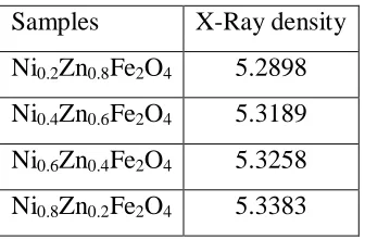
Table 2: Variation of X-Ray density Samples X-Ray density
Ni0.2Zn0.8Fe2O4 5.2898
Ni0.4Zn0.6Fe2O4 5.3189
Ni0.6Zn0.4Fe2O4 5.3258
Ni0.8Zn0.2Fe2O4 5.3383
The X-ray density calculated for the samples synthesized using oxide method are shown
in table 2, it lies in the range of 5.2898 g/cc for Ni0.2Zn0.8Fe2O4 to 5.3383 g/cc for Ni0.8Zn0.2Fe2O4
as the lattice constants decreases the X-ray density is found to increase as it is inversely
proportional to the lattice constant
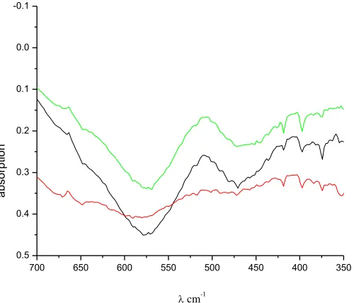
IR Spectroscopy allows us to identify the spinel structure. The three typical vibrational
bonds associated with spinel structure are at (1) 600-550 cm-1 (2) 450-385 cm-1 for metal oxygen
bonds. IR spectra were obtained for all the samples under investigation confirming formation of
The infrared spectra for NixZn(1-x)Fe2O4 where X= 0.2, 0.4, 0.6, and 0.8 ferrite sample is
shown in Fig.2 recorded in the range of 700-400 cm-1
700 650 600 550 500 450 400 350
0.5 0.4 0.3 0.2 0.1 0.0 -0.1
a
b
so
rp
tio
n
[image:5.612.178.428.95.309.2]cm-1
Figure 2: IR spectra of NixZn1-x Fe2O4samples
The IR spectra of samples show two peaks, one in the range 600-550 cm-1 for tetrahedral
stretching vibration and the other 450-385 cm-1 for octahedral stretching vibration corresponding
to spinel structure. For NixZn(1-x)Fe2O4 where X= 0.2, 0.6, and 0.8 sample synthesized by this
modified method two bands in the range at 570-581 cm-1 and 469-476 cm-1 are observed. IR
spectral data of all the ferrite samples are in agreement with the reported value [14].
(a) (b)
Figure 3: SEM micrograph of (a) Ni0.4Zn0.6Fe2O4 and (b)Ni0.8Zn0.2Fe2O4.
As can be seen from the SEM micrograph Fig 3(a) and (b) NixZn(1-x)Fe2O4 samples
[image:5.612.187.466.487.595.2]nickel content. This may be attributed to the lower lattice constants therefore smaller crystallite size
Table 3: Variation of particle size
Concentration of Nickel Particle size in nm
0.2 38.4
0.4 30.2
0.6 27.3
0.8 20.1
The particle size of samples is calculated using the Scherer formula, indicated in table 3
is in the range from 38.4 nm to 20.1 nm. , which also confirmed by the SEM micrograph shown
[image:6.612.170.451.318.567.2]in Figure 3.
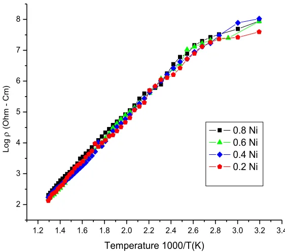
Figure 4: Variation of resistivity (log) with 1000/T (K) for NixZn(1-x)Fe2O4 samples.
The temperature dependence of DC electrical conductivity measured in the temperature
range 300 K - 873 K is shown in the Figure 4. It follows the Arrhenius plot. This graph shows
1.2 1.4 1.6 1.8 2.0 2.2 2.4 2.6 2.8 3.0 3.2 3.4
2 3 4 5 6 7 8
Log
(
O
hm
C
m
)
Temperature 1000/T(K)
that by increasing temperature conductivity increases hence resistivity decreases. This confirms
that the ferrite under investigation has semi conductor behavior. Wherein initially the
conductance is low and it increases with the temperature and also undergoes ferrimagnetic to
paramagnetic transition. The curve has two distinct broad parts; initial parts of curve indicating
low conductance at lower temperature and later on sharp increase with steep slope when
conductance increases or resistivity decreases. The samples show resistivity value in the range
5.5022 X 10⁶ ohm cm to 0.6551 X 10⁸ ohm cm with low value for Ni0.2Zn0.8Fe2O4 and high for
Ni0.8Zn0.2Fe2O4 sample, with increasing Ni2+ from x = 0.2 to x = 0.8. The reason for increase in ρ
on increasing Ni composition is because Zn2+ ions prefer the occupation of tetrahedral sites (A)
and Ni ions prefers the occupation of octahedral sites (B). But Fe ions partially occupies A and B
sites. On increasing Ni concentration at B sites, Zn ions concentration at A sites will decrease.
This leads to migration of some Fe ions from B site to A site to balance the reduction in Zn ions
concentration at A sites. As a result the number of ferric and ferrous ions at B sites which are
responsible for electrical conductivity in ferrites decreases consequently resistivity increases by
increasing Ni ion concentration. [15, 16]. Similar trend of resistivity have been reported by the
other researchers [17]. Electronic conduction mechanisms in ferrites have been studied by many
and various models have been proposed; however, the thermally activated hopping model is
found to be more appropriate in explaining quantitatively the electrical behavior of Ni–Zn ferrite.
In the hopping process the additional electron on ferrous (Fe2+) ion requires little energy to move
to an adjacent (Fe3+) ion on the equivalent lattice sites (B sites). In the presence of the electric
field, these extra electron hopping between iron ions give rise to the electrical conduction.
Therefore any change in the (Fe2+) ion content in spinel ferrite lattice and/or the distance between
them is crucial to the intrinsic resistivity of Ni–Zn ferrite. It is also affected by impurities. The
introduction of another cation into the lattice causes a change in the valence distribution on the B
sites, then the number of electrons potentially available for transfer will be altered. This is crucial
for the conduction mechanism.
References:
[1] S. F. Neues, M.W.E. van den Berg, W. Grunert and L. Khodeir, J. Am. Chem. Soc. 127
(2005) 12028
[3] U.R. Lima, M.C. Nasar, R.S. Nasar, M.C. Rezende and J.H. Araujo, J. Magn. Magn.
Mater. 320 (2008) 1666.
[4] J.-S. Kim, J.-R. Ahn, C.W. Lee, Y. Murakami and D. Shindo, J. Mater. Chem. 11 (2001)
3373.
[5] T. Slatineanu, A.R. Iordan, M.N. Palamaru, O.F. Caltun, V. Gafton and L. Leontie, Mater.
Res. Bull. 46 (2011) 1455
[6] M.U. Islam, T. Abbas, S.B. Niazi, Z. Ahmad, S. Sabeen and M.A. Chaudhry, Solid State
Commun. 130 (2004) 353–356.
[7] Li Xia Wang Guisu, Low temperature synthesis and growth of superparamagnetic
Zn0.5Ni0.5Fe2O4 nanosized particles, J. Magn. Magn. Mater.321 (2009) 1276–1279.
[8] K. Suresh and K.C. Patil, J. Solid State Chem. 99 (1992) 12–17
[9] S. Prasad and N. Gajbhiye, Magnetic studies of nano sized nickel ferrite particles
synthesized by the citrate precursor technique, J. Alloys Compd.265 (1998) 87–92.
[10]Thakur Sangeeta and Katyal S.C. Singh M., Structural and magnetic properties of nano
nickel–zinc ferrite synthesized by reverse micelle technique, J. Magn. Magn. Mater. 321
(2009) 1–7.
[11]D. Chen and R. He, Synthesis of nickel ferrite nanoparticles by sol–gel method, Mater.
Res. Bull. 36 (2001)1369–1377.
[12]Resistivity Measurement (two probe method) Product manual Pushpa Scientific
Hyderabad (2008).
[13]H. Rahmouni, A. Benali, B. Cherif, E. Dhahri, M. Boukhobza, K. Khirouni and M.
Sajieddine “Structural and electrical properties of Zn1-xNixFe2O4 ferrite” Physica B
466-467(2015)31–37
[14]Tamara Slatineanu, Alexandra Raluca Iordan, Mircea Nicolae Palamaru Ovidiu Florin
Caltun, Vasilica Gafton and Liviu Leontie,” Synthesis and characterization of
nanocrystalline Zn ferrites substituted with Ni” Materials Research Bulletin 46 (2011)
1455–1460
[15]U. Ghazanfar, S. A. Siddiqui and G. Abbas, “Study of Room Temperature dc Resistivity
in Comparison with Activation Energy and Drift Mobility of NiZn Ferrite,” Materials
[16]M. E. Shabashy, “DC Electrical Properties of Zn-Ni Ferrites,” J. Magn. Magn. Mater. Vol.
172, No. 1-2, 1997, pp. 188-192.
[17] G. Joshi A. Khot and S. Sawant. “Revised Values of Effective Ionic Radii”, Solid State