2019 International Conference on Information Technology, Electrical and Electronic Engineering (ITEEE 2019) ISBN: 978-1-60595-606-0
Application of Thermo-sensor in Brain-computer Interface
Ming-xiang GUI* and Jing HUANG
1School of Information Science and Engineering, Hunan University, Changsha, China (410000)
2Department, South China University of Technology, Guangzhou, China (510640)
*Corresponding Author
Keywords:Thermo-sensor, The brain-computer interface, Signal acquisition system.
Abstract. The high precise thermo-sensors are introduced to the brain-computer interface for data acquirement. The structures, parameters and properties of most recent thermo-sensors are presented in detail. The suitable signal acquisition system is also discussed in this paper.
Introduction
The performance of brain-computer interfaces (BCIs) is limited by numerous factors such as the nonstationary nature of brain signals, limitations of the signal processing and classification methods used and a limited understanding of the underlying cognitive processes [1]-[2].
Currently, the major recording modalities for BCI are electrophysiological signals. Research by systems neurophysiologists studying motor systems has uncovered how kinematic parameters of movement control are encoded in neuronal firing rates [3], [4]. Capitalizing on these neuroscience findings, several groups were able to develop real-time, closed-loop, BCI systems capable of multidimensional control [5]. Initially, the system was tested on nonhuman primates [5], but electrode arrays have also been implanted in several severely disabled individuals for multidimensional control of a computer cursor [6], [7] or a robotic arm [8], [9].
Actually, the brain or body temperature is another property reflecting response to stimulation. But it is seldom used in these analyses. In this paper, we will introduce two types of thermo-sensors which is available for the data collection and signal detection in the BCI field.
Thermo-sensor for Signal Detection and Data Collection
Highly Sensitive Microfluidic Chip Sensor for Biochemical Detection[10]
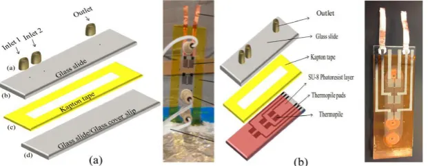
Chip calorimetry offers a power tool for fast and high throughput analysis of biochemical process. We will describe the design of a novel, highly sensitive, and continuous flow microfluidic chip sensor with an integrated antimony (Sb)–bismuth (Bi) thin-film thermopile heat detection element. The device contains a single flow channel that is 120 μm high and 10-mm wide with two fluid inlets and one fluid outlet. An Sb-Bi thin film thermopile is fabricated on the inner surface of the bottom channel wall using thermal evaporation and was passivized with a 3 μm SU-8 photoresist layer.
The sensor can detect dynamic temperature changes in the order of 10−6K. The limit of detection of heat power of the device was calculated to be 8.8 pW. With the obtained remarkable sensitivity and heat power detection limit, the microfluidic chip sensor can potentially be used to investigate biochemical processes, such as enzyme- catalysed reactions, and metabolic activity of cells.
optimized value based on fabrication conditions such as thermal evaporator, and shadow mask technique.
Figure 1. Antimony (Sb)-bismuth (Bi) thin-film thermopile sensor fabricated on a glass coverslip. Enlarged view shows the individual metal lines and thermocouple junctions.
Thermopiles have measuring and reference junction sets (Figure 1). The fabricated thermopiles typically have a resistance of 20 K and showed a Seebeck coefficient of 7.14 μV (mK)−1.
Microfluidic Chip Sensor (MCS). A microfluidic chip sensor (MCS) is fabricated by integrating the thermopile on the channel wall of the microfluidic device. A microfluidic device is fabricated by sandwiching a 100 μm thick dual side adhesive tape (kapton.com) between a microscope glass slide (thickness-1.2 mm and thermal conductivity, k-1.05 W m−1 K−1) and a microscope glass coverslip (thickness-170 μm and thermal conductivity, k-1.05 W m−1 K−1). Before sandwiching, the dual side adhesive tape is cut with a pattern that forms the channel using a Graphtec plotter (Graphtec Inc, USA). Inlet holes (Inlet 1 and Inlet 2) and an outlet hole were pre-drilled onto the microscope glass slide for fluid flow. Two configurations of the microfluidic chip sensors (MCS-1, MCS-2) were fabricated, tested and evaluated. MCS-1 was fabricated with the glass coverslip containing thermopile sensor facing outside of the channel (Figure 2a). The thermopiles are protected by attaching a 25 μm thick tape to prevent damage due to handling. MCS-2 was fabricated with the coverslip containing thermopile sensor facing the channel (Figure 2b). Thermopiles were passivized using a 3 μm thick SU-8 (Microchem, USA, thermal conductivity k-0.2 W m−1 K−1) photoresist layer to protect from the fluid flow.
Thermal resistance (R) for the reaction generated by the flow in the microfluidic channel to the thermopile for both MCS configurations can be calculated by the following equation [12]:
) /(k A L
R where: L- thickness of the layer (m), k-thermal conductivity (W m−1 K−1), and A-area
of the layer (m2). The area for the calculation is the reaction zone area, which is approximately 24
mm2 (the width of the hydrodynamically focused sample is approximately 4 mm and the length of
the thermopile measuring junction’s region is 6 mm). The total thermal resistance in the MCS-1 is due to the thermal resistance of the glass coverslip, which is 6.07 K W−1, and the total thermal resistance in the MCS-2 only the 3 μm thick SU-8 layer which is 0.833 K W−1.
Figure 2. (a) MCS-1 configuration showing the fabrication of microfluidic device with thermopiles outside the fluidic channel. (b) Schematic of the MCS-2 configuration with a SU-8 passivation layer on thermopiles facing inside of the channel. Pictures next to the schematics in A and B are the fabricated MCS configurations. The microfluidic channel
[image:2.595.146.457.617.738.2]Experimental Setup. The experimental setup (Figure 3) used for this study consists of two syringe pumps, which continuously flow water into the inlets of the MCS. Since the flows are in microscale, mixing happens only at the interface as viscosity dominates compared to inertia. This results in a hydrodynamically focused flow [13] in the center, when fluid is flown in inlet 1 and inlet 2 simultaneously (Figure 4). Lee et al. [13] derived the relationship for the width of the hydrodynamic flow in rectangular microfluidic channels as the ratio of the inlet flow rates. An injection valve with a 13 μl sample loop is used to inject the sample into the inlet 2 flow for generating a chemical reaction. The inlet 2 flow is hydrodynamically focused into the MCS. The reaction is generated over the measuring junctions of the thermopile, which generates a proportional voltage.
[image:3.595.154.433.283.388.2]This voltage is detected by a nanovoltmeter (Agilent 34420A, Agilent technologies, USA) and is recorded in a computer. To demonstrate the operation of the MCS, the exothermic nature of glycerol water mixing reaction is utilized. The enthalpies of mixing of water with glycerol over the entire composition range at 298.15 K is determined to be exothermic with a maximum enthalpy of −500 J/mol at molar fraction of 0.5 [14].
Figure 3. Schematic of the experimental setup.
Signal Acquisition System[15]
[image:3.595.199.396.504.612.2]Scalp signal has a very low amplitude ( uV) and their noisy nature make it hard to detect them. Another issue is the DC offset of the signal due to electrode-tissue interface. This DC offset is usually 20-50 mV and about 500 times bigger than the signal. Thus, a very low noise, high input impedance and high CMRR (Common Mode Rejection Ratio) instrumentation amplifier is required to amplify these signals and reject the DC offset.
Figure 4. Architecture of the signal acquisition system.
Figure 5. The instrumentation amplifier AD623 and the passive high-pass filter.
[image:3.595.223.375.644.708.2]The Instrumentation Amplifier and the Passive High-Pass Filter. Due to the high impedance of electrode-tissue interface, a voltage follower is added before the instrumentation amplifier. The schematic of instrumentation amplifier and passive highpass filter is shown in Figure 5.
Instrumentation amplifier AD623 is used as preamplifier. It is an integrated single supply instrumentation amplifier based on a modified classic three op amp approach that delivers railto-rail output swing on a single supply (+3V to +12V supplies). Low-power consumption (1.5mW at 3V), wide supply voltage range, and high CMRR make the AD623 ideal for battery powered medical applications. The gain is set to about 26 dB. It cannot be set to too high because the DC component may be amplified to the saturation state.
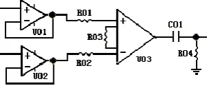
To remove the DC offset component from the output of instrumentation amplifier, a passive high-pass filter with 0.05Hz cut-off frequency is adopted. Otherwise, the offset component may saturate the next stage amplifier. The filter is composed of C01 and R04 as shown in Figure6.
[image:4.595.225.371.377.447.2]The Main Stage Amplifier and the Active Two-Stage Lowpass Filter. The amplitude of signals from the output of instrumentation amplifier is very low and should be further amplified. The TLC27L4 quad operational amplifiers are chosen for the main amplification, which combine a wide range of input offset voltage grades with low offset voltage drift (0.1mV/ Month typically), high input impedance (1012 typically), extremely low-power (195uW at 25°C, VDD = 5V), and high gain. The circuit of the main stage amplifier and two-stage lowpass filter is shown in Figure6. The main stage amplifier has a gain of 21 dB with high precision, low-power non-inverting operational amplifier as in Figure6. The 3 dB cut-off frequency of low-pass filter was set to 35Hz to reduce the power line interference.
Figure 6. The main stage amplifier and the active low-pass filter.
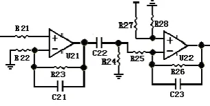
Figure 7. The second stage amplifier and interface coupling circuit.
The Second Stage Amplifier and the Interface Coupling Circuit. The total gain of the instrumentation amplifier and the main stage amplifier is about 51dB, which is not enough for signal amplification. The second stage amplifier with a gain of 21dB and the interface coupling circuit with a gain of 20dB are adopted, as shown in Figure7. Therefore the total gain of the acquisition circuit is about 92 dB. The interface coupling circuit couples the amplified signal and the A/D converters built-in MSP 430 MCU.
[image:4.595.222.375.481.558.2]Conclusion
The thermo-sensor is precise(10-6K) for temperature detection so it can be used in the data acquirement in BCIs. AS an auxiliary data for the accurate judgement of mental diseases, it is an efficient and low-cost.
References
[1] G. Schalk, Brain-computer symbiosis, J. Neural Eng., 5, 2008, 1-15.
[2] B. Z. Allison, E. W. Wolpaw, and J. R. Wolpaw, Brain-computer interface systems: Progress and prospects, Expert Rev. Med. Devices, 4, 2007, 463-474.
[3] A. P. Georgopoulos, J. F. Kalaska, R. Caminiti, and J. T.Massey, On the relations between the direction of two-dimensional arm movements and cell discharge in primate motor cortex, J. Neurosci., 2, 1982, 1527-1537.
[4] A. P. Georgopoulos, A. B. Schwartz, and R. E. Kettner, Neuronal population coding of movement direction, Science, 233,1986, 1416-1419.
[5] D. M. Taylor, S. I. Tillery, and A. B. Schwartz, Direct cortical control of 3D neuroprosthetic devices, Science, 296, 2002, 1829-1832.
[6] L. R. Hochberg, M. D. Serruya, G. M. Friehs, J. A. Mukand, M. Saleh, A. H. Caplan, A. Branner, D. Chen, R. D. Penn, and J. P. Donoghue, Neuronal ensemble control of prosthetic devices by a human with tetraplegia, Nature, 442, 2006, 164-171.
[7] S. P. Kim, J. D. Simeral, L. R. Hochberg, J. P. Donoghue, and M. J. Black, Neural control of computer cursor velocity by decoding motor cortical spiking activity in humans with tetraplegia, J. Neural Eng., 5, 2008, 455-476.
[8] L. R. Hochberg, D. Bacher, B. Jarosiewicz, N. Y. Masse, J. D. Simeral, J. Vogel, S. Haddadin, J. Liu, S. S. Cash, P. van der Smagt, and J. P. Donoghue, Reach and grasp by people with tetraplegia using a neurally controlled robotic arm, Nature,485, 2012, 372-375.
[9] J. L. Collinger, B. Wodlinger, J. E. Downey, W. Wang, E. C. Tyler-Kabara, D. J. Weber, A. J. McMorland, M. Velliste, M. L. Boninger, and A. B. Schwartz, High-performance neuroprosthetic control by an individual with tetraplegia, Lancet, 381, 2013, 557-564.
[10] Varun Lingaiah Kopparthy and Eric J. Guilbeau, Highly Sensitive Microfluidic Chip Sensor for Biochemical Detection, IEEE Sensors Journal, 17, 2017, 6510-6514.
[11] V. L. Kopparthy, S. M. Tangutooru, G. G. Nestorova, and E. J. Guilbeau, Thermoelectric microfluidic sensor for bio-chemical applications,Sens. Actuators B, Chem., 166–167, 2012, 608-615.
[12] T. L. Bergman, F. P. Incropera, D. P. Dewitt, and A. S. Lavine, Fundamentals of Heat and Mass Transfer. Hoboken, NJ, USA: Wiley, 2011.
[13] G.-B. Lee, C.-C. Chang, S.-B. Huang, and R.-J. Yang, The hydrodynamic focusing effect inside rectangular microchannels, J.Micromech. Microeng., 16, 2006,1024.
[14] D. Peetersa and P. Huyskensbp, Endothermicity or exothermicity of water/alcohol mixtures, J. Mol. Struct., 300, 1993, 539-550.