2018 International Conference on Computational, Modeling, Simulation and Mathematical Statistics (CMSMS 2018) ISBN: 978-1-60595-562-9
Direct Torque Control of Interior Permanent Magnet Synchronous
Motors Based on Full-order Sliding-mode Flux Observer
Jin-xia ZHANG
*and Xing-hua ZHANG
College of Electrical Engineering and Control Science, Nanjing Tech University, Nanjing Jiangsu 211816, China
*Corresponding author
Keywords: Interior permanent magnet synchronous motor (IPMSM), Active flux, Full-order
sliding-mode observer, Direct torque control.
Abstract. This paper proposes a full-order sliding-mode stator flux observer. The observer takes the
stator current and “active flux” as the state variables in the stationary reference frame, and can realize “active flux” estimation in the direct torque controlled interior permanent magnet synchronous motor driving system. Therefore, the stator flux and electromagnetic torque can be calculated with estimated "active flux" according to the relationship between "active flux", stator flux and electromagnetic torque. As a result, the IPMSM high-performance speed closed-loop control is achieved. Simulation results are presented to validate the effectiveness of the proposed method.
Introduction
Recently, interior permanent magnet synchronous motors (IPMSMs) are widely used in high-performance ac drive system because of its small size, simple structure, high efficiency and rapid dynamic performance. Generally, high performance motor drive control uses field oriented control (FOC) or direct torque control (DTC). While DTC adjusts torque and stator flux directly in stator coordinate system with torque error and stator flux error, and has advantages of simple control structure, fast dynamic response and less dependent on parameters [1,2]. Stator flux and torque in the DTC drive system are usually estimated by a state observer, and the accuracy of stator flux and torque observations has important influence on the performance of the motor drive system.
Conventional voltage-flux-observer calculates the stator flux by integrating the back electromotive force (EMF) and has advantages of simple structure and less dependent on parameters. However, the sampled stator current and stator voltage always inevitably contain DC components, which saturate the pure integrator output and cause stator flux observation to drift. In addition, the change of stator resistance also affects the accuracy of flux observation. A nonlinear quadrature feedback-compensation stator flux observer has been proposed in [3], which effectively solves the problems of DC drift and magnetic field saturation with voltage-flux-observer. In addition, a stator flux observer proposed in [4,5] is robust to stator resistance perturbation and compensates for the influence of stator resistance variation using stator resistance dynamic identification. Conventional current-flux-observer calculates stator flux by using the permanent magnet flux, stator inductances and rotor position angle, although it does not cause the problem of pure-integrator saturation and is suitable for any speed range, it is more sensitive to motor parameters.
full-order model, and the sliding mode flux observer with stator current observation error as feedback correction is constructed, which improves the robustness of the drive system. By introducing “active flux”, the structure of the observer is simplified, and the dependence on motor parameters is reduced. In addition, the drive system adopts a DTC strategy based on space vector modulation (SVM), which can effectively reduce the torque ripple while maintaining the characteristics of rapid dynamic response of direct torque control[8]. Simulation results are presented to validate that the proposed observer can obtain accurate stator flux and torque observations at full speed range, and the motor drive system has excellent control performance.
Mathematical Model of IPMSM
Voltage equations of IPMSM in the d-q rotating reference frame are
,
,
f e d d e q q q s q
q q e d d d s d
i L i pL i R u
i L i pL i R u
(1)
and electromagnetic torque is given by
, ] ) ( [ 5 .
1 p f d q d q
e n L L i i
T (2) where ud,uq,id,iq,Ld,LqandRsare the stator voltages, stator currents, stator inductances and stator
resistance, respectively, fis permanent magnet flux, npis the number of pole pairs, eis electrical
motor speed, pis the differential operator.
Full-order of Sliding-mode Stator Flux Observer
Design of the Proposed Observer
Using the inverse park transformation, the voltage equations of IPMSM in the -stationary
reference frame are given as
, ,
a e q s
a e q s
i pL i R
u R i pL i
u (3)
where
, sin ] ) ( [
, ] ) ( [
e d q d f a
e d q d f a
i L L
cos i L L
(4)
where u,u,i,i,aanda are the stator voltages, stator currents and “active flux”, respectively, and eis rotor position angle.
It can be seen from (3) that the voltage equations of IPMSM involves only two motor parameters
s
R ,Lqbased on the "active flux", reducing the dependence on the motor parameters and eliminating the salient pole of the motor. Since mechanical variables varies slowly compared with electrical variables, that is, pe0, the derivatives of aand a can be given as
. ,
a e a
a e a
p
p (5)
. , , , a e a a e a a q e q q s a q e q q s α p
p L L
u i L R pi L L u i L R pi (6)
So the full-order sliding-mode stator flux observer can be constructed based on (6), given as
), ˆ sgn( ˆ ˆ ), ˆ sgn( ˆ ˆ ), ˆ sgn( ˆ ˆ ˆ ), ˆ sgn( ˆ ˆ ˆ 2 2 1 1 i i k p i i k p i i k L L u i L R i p i i k L L u i L R i p a e a a e a a q e q q s a q e q q s (7)
where the symbol “^” stands for the estimation variables, k1 is the gain of stator current sliding mode estimator, k2 is the gain of “active flux” sliding mode estimator, and sgn() is the sign function.
Stability Analysis of the Proposed Observer
Subtracting (6) from (7) yields the error dynamic equations
), ~ sgn( ~ ~ ), ~ sgn( ~ ~ ), ~ sgn( ~ ~ ~ ), ~ sgn( ~ ~ ~ 2 2 1 1 i k p i k p i k L i L R i p i k L i L R i p a e a a e a a q e q s a q e q s (8)
where the symbol “~” stands for the errors between estimated variables and actual variables.
To make the estimation errors of stator currents converge to zero, the definite Lyapunov function is considered as
). ~ ~ ( 5 .
0 2 2
1 i i
V (9) Differentiating (9) with respect to time and substituting the dynamic equations of estimation errors of stator currents into it, the following equation is obtained
. ~ ] ~ ~ ) ~ sgn( [ ~ ] ~ ~ ) ~ sgn(
[ 1 1
1 i i
L R L i k i i L R L i k V q s a q e q s a q
e
(10)
Equation (10) shows that, if k1 is large enough, i.e.,
, ~ ~ , ~ ~ max
1
q s a e q s a e L i R L i R
k (11)
then V10is always guaranteed until i~ 0 and ~i 0.
Once stator currents reach the sliding surface, they stay on it and slide along it to the origin. Then the estimated stator currents will converge to actual stator currents. On this point, the following equations can be given by the dynamic equations of estimation errors of stator currents
Substituting (12) into the dynamic equations of estimation errors of “active flux”, the following equations are obtained
. ~ ~
~
, ~ ~
~
1 2 1 2
a q
e a e a
a q e a e a
L k k p
L k k p
(13)
Similarly, in order to make the estimation errors of “active flux” converge to zero, the other positive definite Lyapunov function can be given as
), ~ ~ ( 5 .
0 2 2
2 a a
V (14) then
). ~ ~ ( 2 2 1
2
2 a a
q e
L k k
V (15)
According to Lyapunov stability theory, V20 must be obeyed to guarantee that the observer is stable. Then the parameter k2 can be chosen as 0
1
2
q e
L k
k . Since
1
k and Lq are always positive,
0
2 e
k is needed to be satisfied.
In summary, choosing appropriate gains of current sliding mode observer and “active flux” sliding mode observer can guarantee the convergence of the designed full-order sliding-mode stator flux observer.
Stator Flux and Torque Observations
Since “active flux” can be estimated based on the proposed observer, stator flux can be estimated with “active flux” as
, ˆ
ˆ ,
ˆ ˆ
i L
i L
q a s
q a
s (16)
where ˆs,ˆsare the estimated stator flux in -stationary reference frame.
According to the relationship between torque and stator flux, the estimated torque is given as
). ˆ ˆ ( 5 . 1 ˆ
i i n
Te p s s (17)
System of IPMSM SVM-DTC
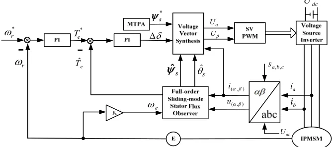
In this paper, SVM-DTC strategy is adopted, and the block diagram of IPMSM SVM-DTC system based on the proposed sliding mode observer is shown in Fig. 1. The reference torque *
e
T can be
obtained by a PI regulator which can regulate the difference between reference speed *
r
and actual speed r. And the difference between reference torque Te* and estimated torque Tˆe are regulated by
a PI regulator, then the torque increment angle is obtained, which includes the torque adjustment information. Therefore, the reference stator flux *
s
contains the adjustment information of torque and stator flux. So torque and stator flux can be controlled simultaneously by regulating the estimated stator flux ˆs to keep track the reference stator flux s*. Here, the reference stator flux
*
s
r
*
e
T
*
s
e
dc
U
U
U
) , (
u ) , (
i ia
b
i s
ˆ
dc
U
c b a
s,,
e
Tˆ
*
r
s
[image:5.612.140.476.72.220.2]ˆ
Figure 1. SVM-DTC control system for IPMSM based on the proposed sliding mode stator flux observer.
Simulation Results
[image:5.612.202.407.340.583.2]In order to verify the validity of the full-order sliding-model stator flux observer proposed in this paper, the control algorithm is built within the Matlab/Simulink environment. The parameters used in the simulation are shown in Table 1.
Table 1. IPMSM Specifications.
Parameter Value
Rated voltage 220[V] Rated speed 2500[rpm] Rated torque 5[N] Number of pole pairs 4 Stator resistance per phase 1.35[Ω]
d-axis inductance 7.6[mH] q-axis inductance 17[mH] Permanent magnet flux 0.132[Wb]
-0.3 -0.2 -0.10 0.1 0.2 0.3
-0.2 -0.1 0 0.1 0.2
0 0.2 0.4 0.6 0.8 1
-0.2 -0.1 0 0.1 0.2
s t/
Figure 2. Stator flux estimation and estimation error.
s t/
-0.2 0 0.2
-0.2 0 0.2
0 0.2 0.4 0.6 0.8 1
-0.05 0 0.05
t/s
-5 0 5
-5 0 5
0 0.2 0.4 0.6 0.8 1
-1 0 1
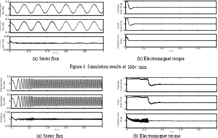
[image:6.612.90.524.76.351.2](a) Stator flux (b) Electromagnet torque Figure 3. Simulation results at 100r/min
s t/
-0.2 0 0.2
-0.2 0 0.2
0 0.2 0.4 0.6 0.8 1
-0.05 0 0.05
t/s
-5 0 5
-5 0 5
0 0.2 0.4 0.6 0.8 1
-1 0 1
(a) Stator flux (b) Electromagnet torque
Figure 4. Simulation results at 1000r/min.
The curves in Fig. 3(a) and Fig. 4(a) are the axis component of estimated stator flux, axis component of actual stator flux and stator flux the estimation error. The curves in Fig. 3(b) and Fig. 4(b) are the estimated torque, the actual torque and the torque estimation error. Here, the actual stator flux and the actual torque are obtained by the conventional current-flux-observer. In the simulation, the given speed is 100r/min and 1000r/min, respectively.
As shown in Fig. 3 and Fig. 4, it can be seen that the estimated stator flux and torque could follow their actual values very well, which shows that the proposed full-order sliding-mode stator flux observer can realize the accurate estimation of stator flux and torque. In addition, due to the introduction of the sliding mode control, when the system reaches the sliding surface, the proposed full-order sliding-mode stator flux observer is completely free from the effects of parameter changes and disturbances. Compared with the conventional current-flux-observer, the robustness to changes in motor parameters is enhanced.
Conclusions
In this paper, an IPMSM full-order sliding-mode stator flux observer is proposed to estimate stator flux and torque by introducing “active flux”, and the design of IPMSM SVM-DTC control system is achieved. The stability of the proposed observer is proved by using Lyapunov function. Compared with conventional observers, the proposed observer not only overcomes the problems of DC offset and dependence on the motor parameters, but has strong robustness to changes of motor parameters and improves the observation accuracy of stator flux and torque.
Acknowledgment
References
[1] Takahashi, Isao Noguchi, Toshihiko, A new quick-response and high-efficiency control strategy of an induction motor, IEEE Transactions on Industry Applications, 1986, pp. 820-827. [2] Depenbrock M., Direct self- control (DSC) of inverter-fed induction machine[J], IEEE Transactions on Power Electronics, 1988, Vol.3, No.4, pp. 420-429.
[3] Jia H.P., He Y.K., A new nonlinear perpendicular flux observer with compensation feedback suitable for DTC application [J], Proc of the CSEE, 2006, Vol. 26, No. 1, pp. 101-105.
[4] Luo M., The flux estimation of permanent magnet synchronous motor based on stator resistance identification[J], Mechatronics, 2014, Vol. 20, No. 8, pp. 33-35.
[5] Wei H.F., Wei H.P., Zhang Y., Dai Y., New stator flux observer of permanent magnet synchronous motor considering stator resistance perturbation under virtual γ-δ rotating coordinate system [J], Control and Decision, 2017, Vol. 32, No.12, pp. 2301-2304.
[6] Zhang X.H., Liu W., Direct torque control of interior permanent magnet synchronous motors based on sliding-mode active flux observers [J], Electric Drive, 2017, Vol. 47, No. 7, pp. 7-11. [7] Zhang M., Xiao X., Li Y.D., Speed and flux linkage observer for permanent magnet synchronous motor based on EKF [J], Proc of the CSEE, 2007, Vol.27, No.36, pp. 36-40.