2018 2nd International Conference on Modeling, Simulation and Optimization Technologies and Applications (MSOTA 2018) ISBN: 978-1-60595-594-0
Modeling and Analysis of Winch Hydraulic Self-running System
Based on AMESim
Jing-tao YUE, Li TANG and Yong-liang ZHOU
Institute of Military Transportation of Army Military Transportation University, China
Keywords: Hydraulic winch, Self-propelled system, AMESim
Abstract. This paper completed the analysis of structural characteristics, control loops, speed solutions and hydraulic motor-driven forms of winch hydraulic system, The system of mathematical models was established which lay the foundation of the establishment of system simulation model. The walking hydraulic drive system simulation models were established by using AMESim software. On this basis, by setting different parameters, the simulation system operating conditions are simulated, which verified the rationality and stability of the design of the winch hydraulic transmission system.
Model Establishment of Hydraulic Transmission System Based on AMESim
The main winch and self-propelled hydraulic drive system of the 20t portable self-driving winch system are mainly composed of power source, variable pump, quantitative motor, control valve, load and so on. The model of variable pump, quantitative motor and other hydraulic components can be simulated correctly by setting the corresponding parameters in (Hydraulic) of AMESim hydraulic storehouse. The realization of the electromagnetic control valve in the control part will not affect the simulation result of the model. The simple signal module in the AMESim signal
library[1]. Signal can be used to simulate the external load, and the external load can be simulated by
the corresponding module in the mechanical library (Mechanical).
Establishment of Simulation Model of Self-propelled System
Figure 1. System hydraulic principle diagram.
Simulation and Analysis
According to the established self-walking and main winch traction hydraulic transmission system model, enter the sub-model mode, select the appropriate mathematical model for each element, and then enter the parameter mode to set parameters for each sub-model. According to the system parameters selection and calculation results set the relevant parameters, other parameters using the default value, finally into the operation mode, set the running time and sampling cycle, click on the
start of the operation, you can get the system simulation results. Equations[2].
Verification of Acceleration Performance of Self-propelled Hydraulic Drive System
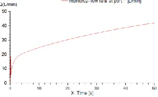
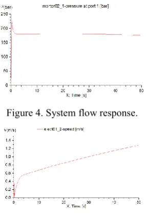
The maximum load torque of the winch self-running system is 3952 Nm under the condition of full load. In order to study the acceleration performance of the system, the displacement ratio of hydraulic pump, the pressure, flow rate and velocity of the system are changed gradually, as shown in Fig.2-Fig.5.
[image:2.595.226.365.490.581.2]The calculation results show that the hydraulic walking system can quickly set up the working pressure after applying the 3952Nm load to the system, and at the maximum load condition
Figure 2. Variation of displacement ratio of variable pump.
[image:2.595.219.378.607.704.2]Figure 4. System flow response.
Figure 5. System Velocity variation.
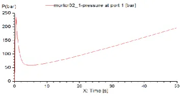
Response of Hydraulic Traveling System of Winch to Slope Load
The response of slope load is to verify the load capacity of hydraulic walking system when it is subjected to increasing load, such as the working condition of moving on a slope with gradually changing slope. To prevent slippage, let the initial load of the system be 2000Nm and gradually
[image:3.595.208.378.379.701.2]increase 3952 Nm. The system change is shown in Fig.6-Fig.9[3].
Figure 6. Slope load of 3952Nm.
Figure 7. Variation of system pressure.
Figure 9. Variation of System Velocity.
The analysis and calculation results show that with the slope load of 3952Nm added to the system, the pressure of the walking system increases steadily with the change of load, which enhances the driving ability of the system, and the flow rate of the system decreases and changes steadily, and the walking speed is similar to the change trend of the flow rate. It is verified that the running speed of hydraulic system depends on the flow rate of the system, but is independent of the load.
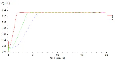
Pressure Response of System to Load Change Rate
The curve shows the slope load of 3952Nm when the load rise time is 0.4 s-1. 2 s, and the pressure response is shown in fig.10- fig.11.
Figure 10. Load at different rates of change.
Figure 10 and figure 11 shows the pressure response of the hydraulic walking system to the slope
load with different changing rate. It can be seen that the hydraulic walking system shows a great
[image:4.595.207.387.521.611.2]pressure change to the load of different rate of change, but tends to be stable soon. The pressure variation corresponding to different rates of load is different. The greater the rate of load change, the greater the pressure fluctuation, but the shorter the time towards stabilization, the better the stability of hydraulic walking system.
Figure 11. Pressure response of system to load.
Pressure Response of System to Load Change Rate
Figure 12. Variable pump discharge ratio change rate.
Figure 13. System velocity response.
Figure 14. Pressure response of the system.
The calculation results show that the pressure of the system varies with the increasing speed of the variable pump displacement. The starting process of the hydraulic traveling system of the winch is also the process of the constant increase of the displacement of the variable pump, and the faster the speed of the variable pump increases, the more the speed of the variable pump increases. The greater the pressure fluctuation, but the shorter the time to achieve stability, in the actual start-up process according to the actual operation conditions reasonable choice of start-up time, in order to reduce the impact of start-up speed on the hydraulic system
Conclusion
The AMESim model of winch hydraulic walking system and main winch system is established, and the performance of the hydraulic system is analyzed. First of all, according to the hydraulic schematic diagram, the simulation model of the winch hydraulic walking system and the main winch system is constructed; secondly, the parameters are set up; finally, the simulation analysis of the two systems under different working conditions is carried out. It is proved that the system has good stability and impact resistance.
References