Development and Testing of an Automatic Turning
Movement Identification System at Signalized Intersections
Kun Xu1,2, Ping Yi2,3*, Chun Shao3, Jialei Mao3
1State Key Laboratory of Information Engineering in Surveying, Mapping and Remote Sensing, Wuhan University, Wuhan, China 2Intelligent Transportation System Research Center, Wuhan University of Technology, Wuhan, China
3Department of Civil Engineering, the University of Akron, Akron, USA
Email: [email protected], *[email protected]
Received May 31, 2013; revised July 2, 2013; accepted August 5, 2013
Copyright © 2013 Kun Xu et al. This is an open access article distributed under the Creative Commons Attribution License, which
permits unrestricted use, distribution, and reproduction in any medium, provided the original work is properly cited.
ABSTRACT
Vehicle turning movement data from signalized intersections is utilized for numerous applications in the field of trans-portation. Such applications include real-time adaptive signal control, dynamic traffic assignment, and traffic demand estimation. However, it is very time consuming and costly to obtain vehicle turning movement information manually. Previous efforts to simplify this process were focused on solving the problem using an O-D matrix, but this method proved to be inaccurate and unreliable with the existing data acquisition system. Another study involved the identifica-tion of vehicle turning movements from the detector informaidentifica-tion, but the presence of shared lanes led to uncertainties in vehicle matching, thus limiting application of the method only to intersections without shared lanes. In light of those unsuccessful attempts, this paper develops and tests a system called the Automatic Turning Movement Identification System (ATMIS), which estimates vehicle turning movements at a signalized intersection in real time, regardless of its geometry. The results from lab experiments as well as a field test show that the algorithm is very promising and may potentially be expanded for field applications.
Keywords: Turning Movement Identification; Signalized Intersection; Detector and Detection; Vehicle Matching; Lab
Experiment and Field Test
1. Introduction
Turning Movement Information (TMI) relates to the num- ber of vehicles completing left or right turns or through movements from each intersection approach. This infor- mation is utilized in many transportation applications and is vital for the improvement of intersection operations. In addition to routine traffic applications, the information can be applied to dynamic traffic assignment, adaptive signal control, and transportation planning. Therefore, it is important to obtain such information accurately and timely in a cost-effective manner.
The traditional method for gathering TMI is a very lengthy process in which observers manually collect data pertaining to the turning movements at a particular inter- section. This method of data collection is not practical in real time and therefore cannot be used for such applica- tions as adaptive signal control logic [1]. With the im- provement in modern vehicle detection systems, Cremer and Keller sought to automatically handle this process by using the O-D matrix method as first introduced in 1981
[2]. Later, Nihan and Davis [3] as well as Cremer and Keller [4] developed a set of dynamic O-D estimation models for intersections and small networks based on the prediction-error minimization method. In their models, the volumes of vehicles flowing in and out of each inter- section approach are used as input parameters. Given these parameters, the O-D matrix is then solved to get the turning movement information. Due to limited volume data available and the fluctuations of traffic flow, the results obtained by the O-D matrix method are not accu- rate for potential applications. In addition, the data col- lection time interval used is too long for this method to be suitable for gathering real-time TMI. Yet another method was developed by Jiao et al. [5] using the Ge-
netic Algorithm to identify TMI. This approach was first introduced in 2003, and the simulation results were en- couraging. However, this method is very sensitive to detection errors commonly seen in the field, associated with the type of detectors used, data reporting intervals, weather conditions, and the geometry of the intersection.
Virkler and Kumar [6,7] at the University of Mis- souri-Columbia developed and tested the Time and Place
Systems (TAPS) method utilizing the phasing and detec- tion information for TMI. TAPS separates right turning vehicles from the through traffic flow using an exclusive lane detector but the left turning vehicles in a shared lane can cause the error to vary from 5% to 70%. In recent years, Chen et al. [8] used a path flow estimator to derive
TMI for an entire roadway network and Zhang et al. [9]
tested a nonlinear programming approach to calculate intersection O-D matrix. Those methods rely on accurate data from a large number of detectors to ensure feasible and stable solutions to the mathematical models; in addi- tion, the TMI is not obtained in small time intervals in support of real time applications.
To make further improvements on the above subject this paper develops and tests a system called the Auto- matic Turning Movement Identification System (AT- MIS). In particular, this system aims at improving data accuracy at intersections and the algorithm is designed to treat shared lanes in different lane configurations.
2. ATMIS Algorithm
The algorithm used in ATMIS makes use of information from both the detectors and the signal system of the in- tersection. By tracking each detector's status and traffic signal operation by the second, vehicle turning move- ments can be calculated. To illustrate the algorithm, con-sider a four-legged intersection as shown in Figure1. In
[image:2.595.308.538.512.736.2]this configuration, there is only one lane at each intersec-tion leg, which means that each lane is shared by left turning, right turning, and through vehicles alike. To de- termine the vehicle turning movements automatically, data obtained from the detectors originally deployed in the intersection for signal control will be used. According to its function, there are two types of detectors: input detectors (white) provide the detection of vehicles ap- proaching the intersection while output detectors (gray) provide the detection of vehicles leaving the intersection.
Figure 1. Detector locations at typical four-legged intersect- tion.
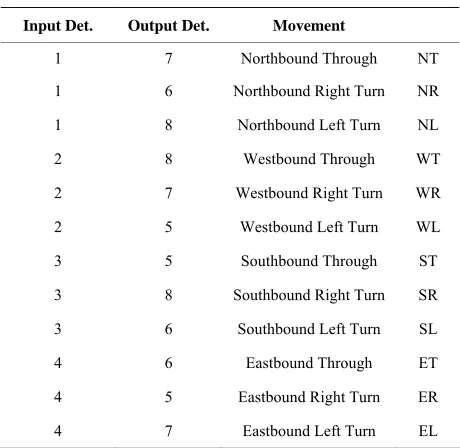
For each turning movement, there is a fixed detector pair to be activated. For example, any northbound left-turning vehicle will first activate detector 1 and then detector 8. Similarly, every turning movement throughout the inter- section can be defined by a sequence of detections, and the resulting sequences are shown in Table1. The algo-
rithm is used to determine vehicle turning movements from a specific detection sequence according to the re- cords of data collected by each detector.
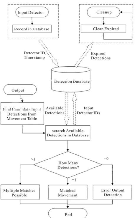
At a signalized intersection, only a fraction of the ap- proaching vehicles can be given the right of way at one moment. Knowledge of the signal phases can help nar- row down the candidate movements. However, the proc- ess of identifying turning movements from a detector pair can still be very complicated when there are multiple possibilities caused by the presence of a shared lane. For instance, a vehicle from detector 6 can be paired with that from detector 1 to provide a northbound right turn, or it can be paired with detector 3 to yield a southbound left turn. The purpose of the algorithm is to identify the turning movement under such complicated circumstances, independent of the geometry of the intersection. The al- gorithm is supported by three modules to handle all pos- sible conditions: the Input Detection Recording Module, the Output Detection Matching Module, and the Input Detection Cleanup Module. Figure2 introduces the de-
tailed procedures of these three modules.
2.1. Input Detection Recording Module
This module is triggered by data received from input detectors, represented by detectors 1 to 4 in Figure 1.
[image:2.595.85.258.549.706.2]Once the status of an input detector changes from acti- vated to deactivated, signifying that the vehicle no longer
Table 1. Turning movement table. Input Det. Output Det. Movement
1 7 Northbound Through NT
1 6 Northbound Right Turn NR
1 8 Northbound Left Turn NL
2 8 Westbound Through WT
2 7 Westbound Right Turn WR
2 5 Westbound Left Turn WL
3 5 Southbound Through ST
3 8 Southbound Right Turn SR
3 6 Southbound Left Turn SL
4 6 Eastbound Through ET
4 5 Eastbound Right Turn ER
Figure 2. Flowchart of ATMIS algorithm.
occupies the detector, the detector’s ID and the deactiva- tion timestamp are recorded and sent to the database. The timestamp is used for two purposes; the first is to match the sequence of the detector pair, and the second is to time-out unmatched detections. The input detections are to be used later in the other two modules.
2.2. Output Detection Matching Module
This module is triggered by data received from output detectors, or detectors 5 to 8 in Figure 1. An output
de-tection is reported when a vehicle has left the detector, and there should be one and only one matching input detection to define the movement as completed. In prac- tice, however, the algorithm will not always return a sin- gle matched input detection from the database. As shown in Figure2, there exist three possible conditions, as de-
scribed below:
1) There is no matched detection in the database. An unmatched detection can be caused either by mis- detection from input detectors or false detection from output detectors. Based on the timestamp associated with
the output data, the algorithm determines that there is no possible input match for the detection. No future detec- tion will provide a match for the error, and the output detection is simply ignored in the algorithm. The error is then recorded and reported by the system.
2) Only one detection match in the database.
This is the best condition for a detection match. The times at which the detections were received allow the system to return a single possible detector pair. The sys- tem simply searches the turning movement table to locate the corresponding movement for the given detection pair. The corresponding input and output detections are then removed from the unmatched list in the database.
3) Multiple detection matches in the database.
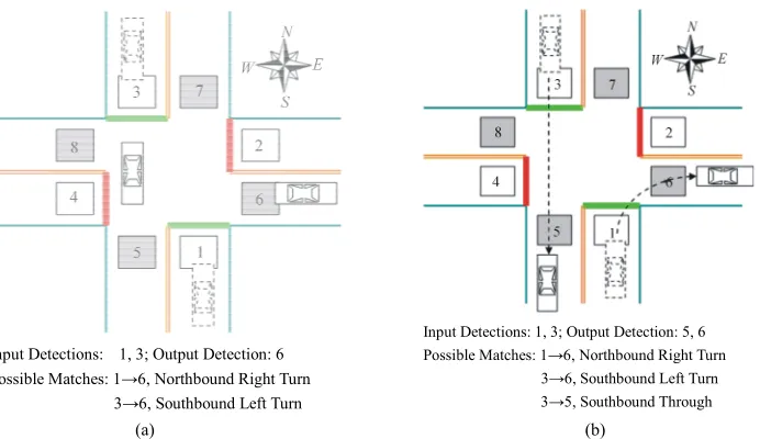
This is the most complicated situation to be addressed by the algorithm. The basic idea behind the process can be illustrated using a simple example. Once again, con- sider a four-legged intersection with one lane in each direction as shown in Figure 3. There is one vehicle
moving from south to east (northbound right turn) while another vehicle travels from north to south (southbound through). At one moment, the vehicles’ positions are shown in Figure 3(a), and two input detections from
detectors 1 and 3 are obtained. When a vehicle leaves detector 6, one output detection will be sent to the system to locate the possible input detection from the database. At this point, the system cannot tell which combination (either with detector 1 or 3) is correct when the signal indication is green for the north-south direction, so the algorithm will hold all the detection data and do not out- put anything.
The multiple matches can be broken up when both ve- hicles have left the intersection. As shown in Figure3(b),
two output detections are now recorded in the database, including one from detector 5. Since a vehicle movement from detector 1 to detector 5 would effectively mean a U-turn, which is not allowed in most cases, only one in-put detection from detector 3 can be a feasible match for output detection 5 at this time. Thus, the algorithm will output the movement “southbound through” and “north- bound right turn” and clear the above recorded detections from the database. In practice, many complex situations like this exist and the algorithm is designed to handle all the possibilities.
2.3. Input Detection Cleanup Module
3.1. Lab Experiments
ration time period is determined according to the specific turning movement trajectory, the length of each relevant
signal phase, and the current signal status. Two intersections have been selected in lab experiments, including the intersections of Fifth Avenue and South Arlington Street, and East Wilbeth Road and South Ar- lington Street in Akron, Ohio. These two intersections are all video camera equipped, and their geometries are quite different. As shown in Figure4(a), the intersection
of Fifth Avenue and South Arlington Street is a standard four-legged intersection with shared lanes. The intersect- tion of East Wilbeth Road and South Arlington Street, shown in Figure4(b), is a T-intersection with only one
lane shared by right turns and through traffic.
3. Experiments and Results
The algorithm of ATMIS has been implemented with the Visual Studio software. To test the feasibility of the al- gorithm, lab experiments and a field test were conducted in a NEMA standard control cabinet with an Autoscope [10] visual detection system. The difference between lab experiments and field test is the video source from the detection system. In lab experiments, the detection sys- tem uses recorded video as the input while in the field test a live feed is utilized. Detection and traffic signal information is collected by a personal computer with an interface card installed in the signal cabinet. The esti- mated turning movements are shown on the computer screen in real time.
For each intersection, daytime traffic was captured by video footage, and the duration of each video varied from 60 minutes to 100 minutes. The ground truth of the turn- ing movements was also collected manually in 20-minute intervals. The results of the experiments at the two inter- sections are depicted in Figures 5 and 6. Those figures
Input Detections: 1, 3; Output Detection: 6 Possible Matches: 1→6, Northbound Right Turn
3→6, Southbound Left Turn
Input Detections: 1, 3; Output Detection: 5, 6 Possible Matches: 1→6, Northbound Right Turn
[image:4.595.129.475.316.516.2]3→6, Southbound Left Turn 3→5, Southbound Through (a) (b)
Figure 3. Input and output detections matching. (a) Undetermined detection matching; (b) Detection matched after both vehi-cles cleared the intersection.
[image:4.595.146.448.557.707.2]
(a) (b)
First Interval 0 20 40 60 80 100 120 140 160 180 200
SR ST SL WR WT WL NR NT NL ER ET EL
Movem ent C ount Ground Truth Estimated First Interval 0 20 40 60 80 100 120 140 160 180 200
SR ST SL WR WT WL NR NT NL ER ET EL
Movem ent
C
ount
Ground Truth Estimated
(a) (b)
First Interval 0 20 40 60 80 100 120 140 160 180 200
SR ST SL WR WT WL NR NT NL ER ET EL
Movem ent C ount Ground Truth Estimated First Interval 0 20 40 60 80 100 120 140 160 180 200
SR ST SL WR WT WL NR NT NL ER ET EL
Movem ent
C
ount
Ground Truth
Estimated
[image:5.595.100.497.84.308.2](c) (d)
Figure 5. Lab experiment results, Fifth Avenue and South Arlington Street.
First Interval 0 20 40 60 80 100 120 140 160 180 200
SR ST SL WR WT WL NR NT NL ER ET EL
Movem ent C oun t Ground Truth Estimated First Interval 0 50 100 150 200 250
ER EL ST SR NL NT
Movem ent
C
ount
Ground Truth Estimated
(a) (b)
First Interval 0 50 100 150 200 250
ER EL ST SR NL NT
[image:5.595.96.500.335.564.2]Movem ent C oun t Ground Truth Estimated (d)
Figure 6. Lab experiment results, East Wilbeth Road and South Arlington Street. show that the estimated vehicle turning movements
re-sulting from ATMIS match very closely to the ground truth data. As shown in Table2, the error percentages in
both cases are relatively small and so are the differences between the percentages between the intersections (4.94% vs. 5.30%). This indicates that ATMIS works well re- gardless of the number of shared lanes included in the two intersections.
It should be noted that the detection error (missing or double counts by the video system) was around 20% during each experiment. This further demonstrates that
3.2. Field Test
ATMIS has good error correction ability.
riments were very encouraging, a field
tion data revealed that during the field test the video de- Although lab expe
test was further performed to verify the accuracy of the ATMIS system in practical applications. This field test took place on a normal working Monday from 11:30 AM to 12:10 PM at the intersection of Fifth Avenue and South Arlington Road and the test results are shown in
Figure7. Compared with the ground truth, the average
Table 2. Matched turning movements and ror percentage of lab experiments. ngton er
Fifth & Arlington Wilbeth & Arli Time Interval
Matched Pairs Error % Matched Pairs Error %
1 461 6.49% 764 3.14%
2 496 5.44% 811 6.66%
3 505 4.75% 804 5.97%
4 518 3.28% No
Aver 5.
data N/A
age 495 4.94% 793 30%
Field Test
0 50 100 150 200 250 300 350
ER ET EL NR NT NL WR WT WL SR ST SL
Movem ent
Co
u
n
t
[image:6.595.130.530.102.691.2]Ground Truth Estimated
Figure 7. Field test results on Fifth Avenue and South Ar lington Street.
had an error rate from 25% to 30% on that ay. Due to site restrictions, the authors were not ab
iments, the results provided by ATMIS ing with an average error of 5% in lab
[1] Transportation ay Capacity
Man-ual,” Washing C, 2000.
[2] M. Cremer and H. Keller, “Dynamic Identification of O-D
nal Symposium on Trans-
Research B, Vol. 21, No. 2, 1987, pp. 149-
-tection system
d le to
go back to and repeat the field test. Nevertheless, the results obtained from the test have demonstrated the data effectiveness and preliminary feasibility of ATMIS for field applications. When more time is given to make ad- justments to the detector positions and calibrate the video system parameters in the future, the results are expected to further improve.
4. Conclusion
Based on the exper are quite encourag
experiments and 8% in preliminary field test. The reason for the estimation errors have been discussed, and im-provements are expected when the data errors due to the video detection system are reduced. Although the testing effort is limited the results have shown that ATMIS is very promising with small estimation errors and the al-gorithm is not noticeably affected by the presence of shared lanes. Further work will be conducted in the re- lated areas to expand the scope of applications and im- prove the system performance.
REFERENCES
Research Board, “Highw
ton D
Flows from Traffic Counts at Complex Intersections,” Pro- ceedings of the 8th Internatio
portation and Traffic Theory, Toronto, 22-24 June 1981,
pp. 121-142.
[3] N. L. Nihan and G. A. Davis, “Recursive Estimation of Origin-destination Matrices from Input/Output Counts,”
Transportation
163.http://dx.doi.org/10.1016/0191-2615(87)90013-0 [4] M. Cremer and H. Keller, “A New Class of Dynamic Me-
thods for the Identification of Origin-destination Flows,”
Transportation Research B, Vol. 21, No. 2, 1987, pp. 117-
132.http://dx.doi.org/10.1016/0191-2615(87)90011-7 [5] P. Jiao, H. Lu and L. Yang, “Real-Time Estimation of
Turning Movement Proportions Based on Genetic Algo- rithm,” Proceedings of the Conference on Intelligent Trans-
Engineering, Vol. 124, No. 6, 1998, pp. 607-609. portation Systems, Vienna, 13-15 September 2005, pp.
96-101.
[6] M. R. Virkler and N. Kumar, “System to Identify Turning Movements at Signalized Intersections,” Journal of Trans- portation
http://dx.doi.org/10.1061/(ASCE)0733-947X(1998)124:6 (607)
[7] J. Tian, M. R. Virkler and C. Sun, “Field Testing for Au- tomated Identification of Turning Movements at Signal-ized Intersection,” Transportation Research Record: Jour- nal of the Transportation Research Board, Vol. 1867, 2004, pp. 210-216.http://dx.doi.org/10.3141/1867-24 [8] A. Chen, P. Chootinan, S. Ryu, M. Lee and W. Recker,
“An Intersection Turning Movement Estimation Proce- dure Based on Path Flow Estimator,” Journal of Advan- ced Transportation, Vol. 46, No. 2, 2012, pp. 161-176.
http://dx.doi.org/10.1002/atr.151
[9] X. Zhang, X. Cao and L. Sun, “Estimation of Intersection Turning Movement Proportion Using MATLAB,” Pro ceedings of CICTP 2012, Beijing,
-
2012, pp. 822-828.
he
[10] P. B. Michalopoulos, B. Wolf and R. Benke, “Testing and Field Implementation of the Minnesota Video Detection System,” Proceedings of 1990 Annual Meeting of t Transportation Research Board, Washington DC, 1990,