MOTOR – COMPRESSOR Laser Shaft Alignment
CLIENTThe client is a large industrial gas producer company located in Jubail Industrial City, Eastern Province, Saudi Arabia.
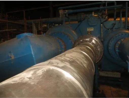
Figure 1. Electric motor on the left with spacer shaft connection thru the sound dampening enclosure.
EQUIPMENTS MEASURED
The equipment/machinery is composed of five (5) motor-compressor trains and one (1) motor-gearbox of an expander unit.
The motor-compressor train setup is a typical electric motor coupled to the compressor using a spacer shaft. The expander unit setup is composed of an electric motor connected to the gearbox using also a spacer shaft.
The motor power rating of the compressor trains ranges from 7.2 MW up to 34.5 MW with an RPM range of 1191 up to 1800. The motor power rating of the expander unit is 671 kW with an RPM of 3587.
Most of the motors are made by ABB except for one made by ALSTOM. One of the motors can be seen of Figure 1. The compressors are all made by Demag Delaval and the gearbox made by BHS Cincinnati.
The spacer shaft length between motor and gearbox of the expander unit is 455 mm and the coupling diameter is 195 mm. For the compressor trains, the spacer shaft length ranges from 2230 mm up to 4268 mm with a coupling diameter range of 440 mm up to 757 mm. One of the spacer coupling can be seen of Figure 2.
PROBLEM
The whole project was a planned outage. Each compressor train was still running and was shut down individually for the scheduled routine maintenance and inspection. The compressor trains supply large amount of process gas to Jubail industrial complex. Therefore, the amount of time for shutdown was planned carefully and any project schedule overrun will have tremendous financial losses and possibly face an industry wide penalty and criticism.
The contractor who won the turnaround project contacted ACQUIP to perform laser shaft alignment. The have shaft alignment team but uses only dial indicators. The client however required the contractor to use laser shaft alignment as part of the project scope for reliability and accuracy.
In addition, the contractor had no previous experience with laser shaft alignment. Part of the project challenge was convincing the contractors’ experienced alignment team and project personnel that using laser equipment for shaft alignment is more reliable and accurate in terms of repeatability check and the most important of all is the amount of time saved over traditional dial indicator setup and readings.
JOB SITE/EQUIPMENT REVIEW
When ACQUIP team arrived on site, it was observed that the compressor trains are mounted three stories or more above ground level.
The compressor was housed inside a sound dampening enclosure due to extreme sound levels during normal operations. It also serves as protection against the elements. However, most of the enclosure was removed while the project was on-going in order to gain easy access to the machinery.
The removal of enclosure leads to the exposure of compressor to direct sunlight. This poses a problem during shaft alignment readings due to thermal growth. Thermal growth influences the readings leading to wrong data analysis, calculation and execution.
Figure 2. One end of the spacer shaft coupling attached to the motor. SOLUTION
Since the removal of enclosure exposes the compressor to direct sunlight on certain time of the day the client, contractor, vendor specialist and ACQUIP agreed to take readings during nighttime.
The massive shafts on some unit also pose a problem during shaft rotation. It was only possible to rotate the shafts thru the use of overhead crane and turning on the lubrication oil system.
On some compressors with different enclosures and setup, difficulty in turning the shafts was experienced. The laser equipment needs to give way to other equipment that aide in shaft rotation. Sometimes other equipment needs to give way to the laser system. It is a matter of placing the equipment using advance bracketing and clever approach did the alignment readings and shaft rotation went thru.
The setup of the laser equipment can be seen of Figure 3 and 4.
After taking the readings, the results were given to the responsible party. Disassembly and inspection of the compressor and auxiliary system commenced right after shaft alignment readings.
ACQUIP team went back on site after the maintenance procedure was completed and the equipment was assembled back to running condition.
Shaft alignment readings were taken again as “Final Check” readings. One big problem that contributed much delay was the breakdown of the overhead crane.
A mobile crane was used as replacement to aid in shaft rotation. During shaft rotation, the boom of the crane exhibited a bend resulting to a “lifting” effect on the shaft rather than “rotating” effect.
During the operation, the lifting capacity of the crane max out and was unable to turn the shaft. The operation was also conducted during the day since the mobile crane cannot operate at night due to very little room to maneuver called “blind lift”. Thermal growth on the compressor was a big concern and the issue was raised to the concerned parties.
The only option was to repair the overhead crane. The project was delayed for a considerable time but the project deadline was not adjusted. ACQUIP was informed to be back on site once the repair is done.
Figure 4. Setup of the laser equipment view from the motor end looking towards the compressor.
When the overhead crane was finally repaired and fully functional, final shaft alignment reading took place.
This time, the advantages of using laser alignment equipment over traditional dial indicators played a key role in catching up to the original project timeframe. From equipment setup to getting repeatable, accurate measurements it took only 30 minutes to 1 hour at most.