www.bmc.com
CONTROL-M
User Guide
Supporting
CONTROL-M/Enterprise Manager version 6.4.01
CONTROL-M/Desktop version 6.4.01
Contacting BMC Software
You can access the BMC Software website at http://www.bmc.com. From this website, you can obtain information about the company, its products, corporate offices, special events, and career opportunities.
United States and Canada
Address BMC SOFTWARE INC 2101 CITYWEST BLVD HOUSTON TX 77042-2827 USA
Telephone 713 918 8800 or 800 841 2031
Fax 713 918 8000
Outside United States and Canada
Telephone (01) 713 918 8800 Fax (01) 713 918 8000
© Copyright 2008 BMC Software, Inc.
BMC, BMC Software, and the BMC Software logo are the exclusive properties of BMC Software, Inc., are registered with the U.S. Patent and Trademark Office, and may be registered or pending registration in other countries. All other BMC trademarks, service marks, and logos may be registered or pending registration in the U.S. or in other countries. All other trademarks or registered trademarks are the property of their respective owners.
Linux is the registered trademark of Linus Torvalds. Oracle is a registered trademark of Oracle Corporation.
UNIX is the registered trademark of The Open Group in the US and other countries.
BMC Software considers information included in this documentation to be proprietary and confidential. Your use of this information is subject to the terms and conditions of the applicable End User License Agreement for the product and the proprietary and restricted rights notices included in this documentation.
Restricted rights legend
U.S. Government Restricted Rights to Computer Software. UNPUBLISHED -- RIGHTS RESERVED UNDER THE COPYRIGHT LAWS OF THE UNITED STATES. Use, duplication, or disclosure of any data and computer software by the U.S. Government is subject to
restrictions, as applicable, set forth in FAR Section 52.227-14, DFARS 252.227-7013, DFARS 252.227-7014, DFARS 252.227-7015, and DFARS 252.227-7025, as amended from time to time. Contractor/Manufacturer is BMC SOFTWARE INC, 2101 CITYWEST BLVD, HOUSTON TX 77042-2827, USA. Any contract notices should be sent to this address.
3
Customer support
You can obtain technical support by using the BMC Software Customer Support website or by contacting Customer Support by telephone or e-mail. To expedite your inquiry, see “Before contacting BMC.”
Support website
You can obtain technical support from BMC 24 hours a day, 7 days a week at http://www.bmc.com/support_home. From this website, you can
■ read overviews about support services and programs that BMC offers
■ find the most current information about BMC products
■ search a database for issues similar to yours and possible solutions ■ order or download product documentation
■ download products and maintenance ■ report an issue or ask a question
■ subscribe to receive proactive e-mail alerts when new product notices are released
■ find worldwide BMC support center locations and contact information, including e-mail addresses, fax numbers, and
telephone numbers
Support by telephone or e-mail
In the United States and Canada, if you need technical support and do not have access to the web, call 800 537 1813 or send an e-mail message to [email protected]. (In the subject line, enter SupID:<yourSupportContractID>, such as SupID:12345). Outside the United States and Canada, contact your local support center for assistance.
Before contacting BMC
Have the following information available so that Customer Support can begin working on your issue immediately:
■ product information
— product name
— product version (release number)
— license number and password (trial or permanent)
■ operating system and environment information
— machine type
— operating system type, version, and service pack or other maintenance level such as PUT or PTF — system hardware configuration
— serial numbers
— related software (database, application, and communication) including type, version, and service pack or maintenance level
■ sequence of events leading to the issue
■ commands and options that you used
■ messages received (and the time and date that you received them)
— product error messages
— messages from the operating system, such as file system full
License key and password information
If you have questions about your license key or password, contact BMC as follows:
■ (USA or Canada) Contact the Order Services Password Team at 800 841 2031, or send an e-mail message to [email protected].
■ (Europe, the Middle East, and Africa) Fax your questions to EMEA Contracts Administration at +31 20 354 8702, or send
an e-mail message to [email protected].
5
Contents
About this book 17 Conventions . . . 18Syntax statements. . . 18
Part 1
Getting started
21
Chapter 1 Introduction to CONTROL-M/Enterprise Manager 23 Automating your production jobs with CONTROL-M/EM . . . 23Where to go from here. . . 24
Chapter 2 Working with CONTROL-M/Desktop and CONTROL-M/EM 25 Starting CONTROL-M/Desktop . . . 26
Connecting to a different GUI Server . . . 27
Starting CONTROL-M/EM . . . 27
Troubleshooting connectivity problems . . . 28
Understanding the CONTROL-M/Desktop and CONTROL-M/EM layout . . . 31
Understanding the flow diagram . . . 33
Recognizing job dependencies. . . 36
Adjusting the display . . . 37
Returning panes to their original positions . . . 37
Changing the data display format . . . 37
Displaying dependency names in a node . . . 38
Focusing on different level nodes (stepping in and stepping out) . . . 38
Performing other display adjustments. . . 39
Filtering the jobs displayed in a CONTROL-M/Desktop draft . . . 40
Arranging the CONTROL-M/Desktop flow diagram display . . . 41
Changing click and drag in CONTROL-M/Desktop to define dependencies . . 42
Creating workspaces and loading jobs into CONTROL-M/Desktop . . . 42
Navigating in the flow diagram . . . 43
Identifying predecessor and successor jobs . . . 44
Printing the flow diagram . . . 45
Part 2
Defining the production environment
47
Chapter 3 Introduction to defining the production environment 49
Defining the production environment . . . 49
Understanding workspaces . . . 50
Where to go from here . . . 50
Chapter 4 Defining how jobs should run 53 Defining job processing definitions and scheduling groups—basic procedure . . . 54
Creating and editing jobs . . . 57
Assigning a name to the job . . . 58
Identifying the task type and related information . . . 58
Defining a job to run a CONTROL-M/Server utility . . . 61
Defining the job hierarchy . . . 63
Defining the job’s owner and author . . . 63
Defining job documentation. . . 63
Defining scheduling criteria for a job—basics . . . 64
Defining scheduling criteria using calendars . . . 65
Defining complex scheduling criteria using rules. . . 66
Limiting scheduling to a particular date range . . . 71
Permitting scheduling even after the scheduling date passed . . . 73
Defining cyclic jobs . . . 73
Defining automatic rerun for a job that ends NOT OK . . . 75
Defining jobs that should run on specific nodes . . . 76
Defining jobs that should run on nodes where load balancing has been implemented . . . 77
Defining a time frame during which jobs can be submitted . . . 77
Defining that manual confirmation is required before job submission . . . 78
Assigning priorities to jobs and defining and critical jobs. . . 79
Defining how many days a job can await submission . . . 80
Defining dependencies for the current job . . . 81
Allocating resources for a job . . . 83
Defining and using variables that are dynamically resolved at runtime . . . 84
Defining postprocessing actions that depend on job processing results . . . 87
Defining conditional processing under z/OS . . . 94
Defining messages to be shouted at the end of job processing . . . 96
Defining how to handle the job’s sysout when the job ends OK . . . 98
Archiving sysdata (z/OS only) . . . 99
Creating and editing scheduling groups. . . 99
Defining general scheduling group information. . . 100
Defining scheduling criteria for a scheduling group . . . 101
Defining dependencies, variables, and notifications in the scheduling group. . 103
Defining actions to be performed after all scheduled jobs in the table have ended 104 Creating and editing jobs in a group scheduling table . . . 106
Defining scheduling criteria for a job in a group scheduling table . . . 106
7
Defining a condition format. . . 110
Chapter 5 Organizing and managing jobs in scheduling tables 113 Introduction . . . 113
Managing scheduling tables. . . 114
Managing jobs and scheduling groups. . . 118
Chapter 6 Comparing jobs 123 Introduction . . . 123
Comparing jobs . . . 123
Chapter 7 Organizing and managing job versions 125 Introduction . . . 125
Managing job versions . . . 126
Managing deleted jobs . . . 127
Examples . . . 128
Modified Job . . . 128
Deleted Job . . . 129
Calendar change . . . 130
Chapter 8 Using predefined calendars to schedule jobs 133 Introduction . . . 133
Creating and modifying calendars . . . 134
Managing calendars. . . 137
Uploading and downloading calendars. . . 138
Copying calendars. . . 138
Deleting calendars . . . 139
Refreshing and unlocking calendars . . . 139
Chapter 9 Setting up templates for standardized job definition 141 Defining templates. . . 142
Adding functions to template fields . . . 143
Managing templates . . . 145
Chapter 10 Creating and updating many jobs at once 147 Introduction . . . 147
Creating large numbers of jobs . . . 147
Finding and updating many entities at once . . . 148
Finding and updating jobs and scheduling groups . . . 149
Managing updated jobs . . . 154
Chapter 11 Setting up definitions for periodic statistics collection 155 Introduction . . . 155
Defining periodic statistics definitions . . . 156
Managing periodic statistics definitions . . . 157
Part 3
Moving to production
161
Chapter 12 Introduction to moving to production 163 Moving to production . . . 163Where to go from here . . . 163
Chapter 13 Putting jobs into production 165 Writing tables to the CONTROL-M/EM database . . . 165
Uploading tables to the CONTROL-M database . . . 166
Manually scheduling jobs and tables. . . 168
Downloading tables from CONTROL-M to CONTROL-M/EM . . . 170
Chapter 14 Automating job scheduling and maintenance 173 Identifying automation criteria for scheduling tables. . . 174
Chapter 15 Identifying data center resources available for CONTROL-M use 175 Introduction. . . 175
Filtering resources on startup . . . 176
Allocating control resources . . . 177
Viewing the list of jobs and tables that use a control resource . . . 178
Defining quantitative resources . . . 179
Chapter 16 Establishing job dependencies across CONTROL-Ms 183 Defining global conditions . . . 183
Deleting global conditions. . . 185
Global condition logic and examples. . . 186
Best practices . . . 188
Frequent updates to a global condition (toggles) . . . 188
Bi-directional global conditions . . . 188
Part 4
Monitoring and intervening in production
195
Chapter 17 Introduction to monitoring and intervention 197 Monitoring and intervening in production . . . 197Where to go from here . . . 197
Chapter 18 Ensuring CONTROL-M components are communicating 199 Communicating with the GUI Server . . . 199
Automatically reconnecting to the GUI Server . . . 199
9
Chapter 19 Selecting jobs to monitor 203 Introduction . . . 204
Selecting a ViewPoint . . . 204
Displaying nodes in their own ViewPoint. . . 205
Filtering the ViewPoint display . . . 205
Switching filters . . . 205
Defining dynamic filters . . . 206
Defining global filters . . . 208
Defining ViewPoints . . . 210
Defining the set of jobs to load to memory (collections) . . . 211
Defining the display hierarchy . . . 212
Alternative method for defining ViewPoints — the ViewPoint wizard . . . 213
Chapter 20 Monitoring and handling alerts 215 Introduction . . . 215
Connecting to the Global Alerts Server . . . 216
Displaying alerts. . . 216
Working with alerts . . . 217
Chapter 21 Monitoring and intervening in production 221 Monitoring . . . 221
Checking job status summaries by CONTROL-M, application, and group . . . . 222
Checking job status details. . . 223
Performing job monitoring actions . . . 223
Checking predecessor and successor job flows. . . 224
Intervening . . . 228
Viewing and editing the details of a job in the active environment . . . 228
Performing manual job intervention . . . 230
Handling errors that occur when you intervene . . . 234
Manually indicating satisfied conditions. . . 234
Manually rescheduling jobs in the active environment. . . 236
Activating third-party applications . . . 239
Chapter 22 Monitoring business-critical batch services using BMC Batch Impact Manager 243 Introduction to BMC Batch Impact Manager. . . 243
BMC Batch Impact Manager integration . . . 244
Using CONTROL-M/EM to track business services . . . 245
Part 5
Analyzing and optimizing the production environment 249
Chapter 23 Introduction to analyzing and optimizing production 251 Analyzing and optimizing the system . . . 251Chapter 24 Defining and generating reports 253
Introduction. . . 253
Starting the CONTROL-M Reporting facility. . . 254
Changing CONTROL-M/EM environments for reporting . . . 255
Generating a report . . . 258
Displaying and working with reports . . . 258
Defining templates and single-use reports . . . 259
Generating and exporting reports in batch. . . 263
Using command line parameters. . . 264
Input arguments file . . . 265
Using the Report tab (optional) . . . 268
Available report types . . . 270
Active report types. . . 270
Definition report types . . . 271
General report types . . . 272
BMC Batch Impact Manager report types . . . 273
CONTROL-M/Forecast report types . . . 273
Converting old reports. . . 273
Chapter 25 Viewing and playing back archived data 275 Selecting and displaying archived ViewPoints . . . 276
Playing back archived events . . . 277
Chapter 26 Planning production with CONTROL-M/Forecast 279 Introduction to CONTROL-M/Forecast . . . 279
CONTROL-M/Forecast integration . . . 280
Part 6
Appendixes
283
Appendix A Customizing the interfaces 285 Changing your password . . . 285Adjusting list displays . . . 285
Modifying list displays . . . 286
Customizing default options . . . 289
Setting options for CONTROL-M/Desktop. . . 289
Setting options for CONTROL-M/EM . . . 297
Setting options for the CONTROL-M Reporting facility . . . 304
Appendix B Examples for defining jobs 307 Accessing the sample draft . . . 307
Organizing the company’s accounting jobs — the Ex-Accounting application . . . . 308
Handling invoicing needs. . . 308
Handling payroll processing needs. . . 311
Organizing the airline company’s flight jobs — the Ex-Flights application . . . 313
11
Organizing the IT department maintenance jobs — the Ex-ITMaintenance application . . . . 315
Handling IT job backup needs. . . 315
Handling emergency situations . . . 318
Handling component shutdown needs . . . 321
Appendix C Formats, values and functions 325 Pattern-matching strings. . . 325
Using SQL wildcards . . . 328
Valid functions for Template editor and condition formats . . . 329
Appendix D Checking job processing definition validity 331 Checking the validity of job processing definitions . . . 331
13
Figures
CONTROL-M/Desktop displaying a draft . . . 31CONTROL-M/Enterprise Manager displaying a ViewPoint . . . 32
Condition node in the flow diagram . . . 38
Job editing form . . . 55
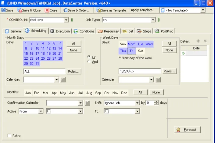
Scheduling tab in the job editing form . . . 64
Scheduling tab in the group editing form . . . 102
Scheduling Table Manager . . . 114
Job List dialog box . . . . 120
Job Comparison dialog box . . . 124
Calendar Manager dialog box . . . 134
Calendar definition dialog box . . . 135
Template Manager . . . 142
Template editing form . . . 143
Find and Update window . . . 149
Order/Force Parameters dialog box (in CONTROL-M/Desktop) . . . 169
Filter Definition dialog box . . . 209
Alerts Window . . . 216
Order/Force dialog box with advanced fields (in CONTROL-M/EM) . . . 238
Filled in Activate Applications Editor dialog box . . . 241
CONTROL-M/EM Business Services window . . . 245
Reporting Facility Start Page window . . . 255
Report template filter definition . . . 267
emreportcli - Report tab . . . 269
Column header pop-up menu for list displays . . . 286
15
Tables
Node and tree icons . . . 33Additional icons in CONTROL-M/EM only . . . 34
Job status indicated color . . . 34
High-level node status colors - Defaults . . . 35
Sample node types . . . 36
Additional display adjustments . . . 39
CONTROL-M/Server utility jobs . . . 61
Valid date values for In and Out conditions . . . 82
DO actions . . . 91
Determining which jobs in a group scheduling table get scheduled . . . 108
Table management tasks . . . 115
Job management tasks . . . 118
Job comparison tasks . . . 124
Job version management tasks . . . 126
Deleted jobs management tasks . . . 127
FIND and Update actions . . . 151
FIND operators . . . . 152
Update Operators . . . 152
Periodic statistics management tasks . . . 157
Communication Status dialog box fields and symbols . . . 201
Job monitoring actions . . . 223
Fields of the Active tab . . . 229
Job intervention actions . . . 231
Bypass options . . . 232
Where to look for integrated features in CONTROL-M/EM . . . 244
emreportcli parameters . . . 264
emreportcli utility input arguments file description . . . 266
emreportcli report generation utility parameters . . . 268
Where to look for integrated features in CONTROL-M/Desktop . . . 281
General settings (General panel) . . . 290
Workspace settings (General – Workspace panel) . . . 291
General flow diagram settings (Flowdiagram – General panel) . . . 292
Flow diagram node settings (Flowdiagram - Nodes panel) . . . 292
Flow diagram condition settings (Flowdiagram – Links panel) . . . 293
Flow diagram color settings (Flowdiagram – Colors panel) . . . 294
Diagnostic settings (Diagnostic panel) . . . 294
Forecast settings (Forecast panel) . . . 296
General environment settings (Environment General panel) . . . 298
Environment Display panel default settings . . . 299
Reconnection panel default settings . . . 302
Environment panel . . . 304
Viewer Panel . . . 304
Symbols used to compose pattern-matching strings . . . 326
Examples of expressions . . . 327
About this book 17
About this book
This book contains procedures that you perform with the CONTROL-M/Enterprise Manager product, to automate, monitor, and intervene in your production
environment. This book is intended for all users of CONTROL-M/Enterprise Manager (CONTROL-M/EM).
The book is organized into parts that reflect the logical progression of high-level tasks. Each part contains the chapters that organize the individual implementation tasks into related chapters. To use the information in this book most effectively, read the chapters in the order in which they are presented.
Like most BMC Software documentation, this book is available in printed and online formats. Visit the BMC Software Customer Support page at
http://www.bmc.com/support_hometo request additional printed books or to view online books and notices (such as release notes and technical bulletins). Some product shipments also include the online books on a documentation CD.
The software also offers online Help. To access Help, press F1 within any product, or click the Help button in graphical user interfaces (GUIs).
NOTE
■ BMC Software recommends that before you use this book, you become familiar with the concepts presented in the CONTROL-M Concepts Guide.
■ This book assumes that CONTROL-M is already installed and initially configured. The installation and configuration tasks are described in the CONTROL-M Installation Guide. ■ This book does not discuss administrative tasks (for example, daily maintenance). Those
tasks are described in the CONTROL-M Administrator Guide.
NOTE
Online books are formatted as Portable Document Format (PDF) or HTML files. To view, print, or copy PDF books, use the free Adobe Reader from Adobe Systems. If your product installation does not install the reader, you can obtain the reader at http://www.adobe.com.
Conventions
Conventions
This book uses the following special conventions:
■ All syntax, operating system terms, and literal examples are presented in this typeface.
■ Variable text in path names, system messages, or syntax is displayed in italic text:
testsys/instance/fileName
■ The symbol => connects items in a menu sequence. For example,
Actions => Confirm instructs you to choose the Confirm command from the Actions menu.
Syntax statements
The following example shows a sample syntax statement:
The following table explains conventions for syntax statements and provides examples:
COMMAND KEYWORD1 [KEYWORD2 | KEYWORD3] KEYWORD4={YES | NO} fileName...
Item Example
Items in italic type represent variables that you must replace with a name or value. If a variable is represented by two or more words, initial capitals distinguish the second and subsequent words.
alias
databaseDirectory serverHostName Brackets indicate a group of optional items.
Do not type the brackets when you enter the option. A comma means that you can choose one or more of the listed options. You must use a comma to separate the options if you choose more than one option.
[tableName, columnName, field] [-full, -incremental, -level]
(Unix)
Braces indicate that at least one of the enclosed items is required. Do not type the braces when you enter the item.
{DBDName | tableName}
UNLOAD device={disk | tape,
fileName | deviceName} {-a | -c} (Unix)
About this book 19 Syntax statements
A vertical bar means that you can choose only one of the listed items. In the example, you would choose either commit or cancel.
{commit | cancel}
{-commit | -cancel} (Unix) An ellipsis indicates that you can repeat the
previous item or items as many times as necessary.
columnName . . .
Part 1 21
1
Part
Part 1
Getting started
This part presents the following topics: Chapter 1
Introduction to CONTROL-M/Enterprise Manager . . . 23
Chapter 2
Chapter 1 Introduction to CONTROL-M/Enterprise Manager 23
C h a p t e r
1
1
Introduction to
CONTROL-M/Enterprise Manager
This chapter presents the following topics:
Automating your production jobs with CONTROL-M/EM . . . 23 Where to go from here. . . 24
Automating your production jobs with
CONTROL-M/EM
With CONTROL-M/Enterprise Manager, you can automate the scheduling and processing of your production jobs. Its main GUIs are CONTROL-M/Desktop and the CONTROL-M/Enterprise Manager window (simply called CONTROL-M/EM). To automate your production environment, perform the following tasks:
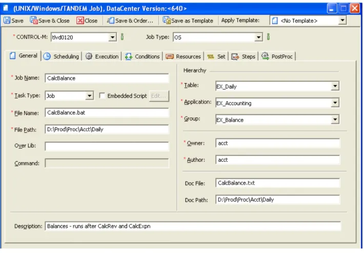
■ Model your production job flow by using job processing definitions Job processing definitions provide CONTROL-M with the instructions for scheduling, submitting, and performing post-processing tasks of the jobs in your production environment. This book describes how to use CONTROL-M/Desktop to create job processing definitions and other needed entities.
■ Automate job ordering
After job processing definitions have been defined for your production jobs, you perform several tasks to transition your definitions to production. As part of this transition, you can use a feature called New Day processing to automate the ordering of jobs each day.
Where to go from here
■ Monitor (and where necessary, intervene in) the processing of your production jobs
To ensure that everything is running smoothly, you can monitor job processing, and if problems arise you can intervene effectively. Generally, monitoring by exception (that is, checking problems or potential problems rather than viewing the entire system) is the most effective way to monitor your production jobs. ■ Analyze (and optimizing) job processing in your production jobs
After your production jobs have been automated, you can ensure that processing is maximized by using analysis tools to identify areas that can be improved, such as resource allocation, work balancing, and so on.
This book describes how to use the GUIs of CONTROL-M/EM to automate the scheduling and processing of your production jobs.
Where to go from here
■ Continue with Chapter 2, “Working with CONTROL-M/Desktop and
CONTROL-M/EM,” which explains how to start CONTROL-M/Desktop and CONTROL/EM, and provides the details that you need to navigate, understand, and effectively use these interfaces.
■ For details about defining the entities needed for automating the production environment, especially job processing definitions, see Part 2, “Defining the production environment.”
■ For details about how to transition your definitions into production and automating your production environment, see Part 3, “Moving to production.”
■ For details about monitoring, and when necessary, intervening in, your production environment after it is automated, see Part 4, “Monitoring and intervening in production.”
■ For details about helpful tools (including reports) for analyzing and optimizing your production environment, see Part 5, “Analyzing and optimizing the production environment.”
Chapter 2 Working with CONTROL-M/Desktop and CONTROL-M/EM 25
C h a p t e r
2
2
Working with CONTROL-M/Desktop
and CONTROL-M/EM
Starting CONTROL-M/Desktop . . . 26 Connecting to a different GUI Server . . . 27 Starting CONTROL-M/EM . . . 27 Troubleshooting connectivity problems . . . 28 Understanding the CONTROL-M/Desktop and CONTROL-M/EM layout . . . 31 Understanding the flow diagram . . . 33 Recognizing job dependencies. . . 36 Adjusting the display . . . 37 Returning panes to their original positions . . . 37 Changing the data display format . . . 37 Displaying dependency names in a node . . . 38 Focusing on different level nodes (stepping in and stepping out). . . 38 Performing other display adjustments. . . 39 Filtering the jobs displayed in a CONTROL-M/Desktop draft . . . 40 Arranging the CONTROL-M/Desktop flow diagram display. . . 41 Changing click and drag in CONTROL-M/Desktop to define dependencies. . . 42 Creating workspaces and loading jobs into CONTROL-M/Desktop . . . 42 Navigating in the flow diagram. . . 43 Identifying predecessor and successor jobs . . . 44 Printing the flow diagram. . . 45 Changing your password . . . 46
This chapter provides basic information you need to start, understand, navigate, and manipulate CONTROL-M/Desktop and CONTROL-M/EM features.
■ CONTROL-M/Desktop enables you to create and edit job processing definitions, one of the first tasks that you are likely to perform. CONTROL-M/Desktop also enables you to define other entities such as scheduling tables, job templates and calendars. After defining these entities, you can use CONTROL-M/Desktop to move entities that you have defined into production.
Starting CONTROL-M/Desktop
■ CONTROL-M/EM enables you to monitor and intervene in job processing in the production environment. The selection of jobs you view is called a ViewPoint. ViewPoints are discussed in Chapter 19, “Selecting jobs to monitor.”
You should become familiar with the information in this chapter before using CONTROL-M/Desktop to define job processing definitions (and other entities), and before using CONTROL-M/EM to monitor and intervene in your production environment.
Starting CONTROL-M/Desktop
1
Choose Start => Programs => CONTROL-M Enterprise Manager => CONTROL-M/Desktop.2
Enter your user name and password, select the CONTROL-M/EM GUI Server to which you want to connect, and click Login.If change password fields are displayed, your password is soon due to expire. Fill in your new password, and then confirm it.
The CONTROL-M/Desktop window is displayed.
3
If the Load Jobs dialog box is displayed (which depends on configuration options), to load jobs from CONTROL-M/EM into CONTROL-M/Desktop:A
Select the jobs and tables to be loaded, and click Load, and confirm if necessary. The Load Scheduling Table Results dialog box displays the results of the load operation.B
Close the Load Scheduling Table Results dialog box.TIP
If the GUI Server to be selected is not listed, contact your CONTROL-M administrator.
NOTE
If tables you select are locked, notify the user named in the Locked by column, or wait until the tables are unlocked.
Connecting to a different GUI Server
Chapter 2 Working with CONTROL-M/Desktop and CONTROL-M/EM 27
Connecting to a different GUI Server
CONTROL-M/Desktop enables you to connect to a different GUI Server at any time. (To check to which GUI Server you are currently connected, choose
Tools => Connection => Connection Properties.)
To change connection to a different GUI Server
1
In CONTROL-M/Desktop, choose Tools => Connection => Connect with Different Properties.2
Enter your user name and password, and select the GUI Server to which you want to connect.3
To specify values other than the defaults for host name, port number and Secured Socket Layer usage, click Advanced, and fill in the details.4
Click Login.Starting CONTROL-M/EM
1
Choose Start => Programs => CONTROL-M Enterprise Manager => CONTROL-M/Enterprise Manager GUI.2
Enter your user name and password, select the CONTROL-M/EM GUI Server to which you want to connect, and click Login.If change password fields are displayed, your password is soon due to expire. Fill in your new password, and then confirm it.
3
To display jobs that are in the production environmentA
Choose File => Open ViewPoint.B
In the Open ViewPoint dialog box, select the ViewPoint to be used for displaying jobs.C
To filter jobs that will be displayed in the selected ViewPoint, click Dynamic Filter in the Open ViewPoint dialog box.TIP
Troubleshooting connectivity problems
Then do the following actions in the Dynamic Filter dialog box: ■ Optionally, select your previously defined Filter Preset.
■ Fill in the fields for filtering. For details, see “Defining dynamic filters” on page 206.
■ Click OK in the Dynamic Filter dialog box.
D
Click OK in the Open ViewPoints dialog box to open the ViewPoint in the CONTROL-M/EM window and display the selected jobs.Troubleshooting connectivity problems
This section provides information on how to troubleshoot problems connecting the CONTROL-M/EM server to CONTROL-M/EM and CONTROL-M/Desktop. The CONTROL-M/EM GUI and CONTROL-M/Desktop use a callback connection method for several actions such as Upload Table and Open ViewPoint.
CONTROL-M/EM uses a single XML CORBA configuration file, called config.xml that defines CORBA configuration data for all CORBA components (clients and servers included). During installation, the file is configured with default values for the components. Sometimes, when the client machine has more than one IP address, the default configuration does not provide optimum performance, resulting in a failure.
If the callback connection fails during login, the Connectivity Failure window is displayed, warning the user about the connectivity failure. Ignoring this warning message may result in a failure to open a ViewPoint or upload or order a table from the CONTROL-M/EM server.
The Connectivity Failure window indicates that the CONTROL-M/EM server is not connected to CONTROL-M/EM GUI client and CONTROL-M/Desktop. The
Connectivity Failure window enables the user to resolve the problem either automatically or manually.
During the automatic resolution, all available IP addresses are scanned, the best IP address (with the shortest response time) is identified, and the CORBA configuration file is modified accordingly.
Alternately, the user can manually resolve the connectivity problem, by specifying connection configurations and testing them.
Troubleshooting connectivity problems
Chapter 2 Working with CONTROL-M/Desktop and CONTROL-M/EM 29
To automatically resolve a connectivity problem
1
Click Repair to allow for automatic identification of available IP addresses. The connectivity problem is automatically resolved by using the IP address displayed in the window.2
Click Close.To manually resolve a connectivity problem
1
Click Advanced to open the Troubleshoot Connectivity window.2
In the Troubleshoot Connectivity window, temporarily clear the Use bidirectional communication check box for this procedure.3
Select one of the following:NOTE
If the automatic resolution failed, use the manual resolution procedure described below, ensuring that the Use bidirectional communication check box is selected.
NOTE
The configuration changes affect the entire installation, including client and server processes that were running while the changes were made. You should restart every running
CONTROL-M/EM application, such as the CONTROL-M/EM GUI client, CONTROL-M/EM GUI server, CONTROL-M/Desktop, GAS server, CONTROL-M/Forecast server, BMC Batch Impact Manager server, and CMS server.
NOTE
The Use bidirectional communication check box at the bottom of the window reflects the value of the -BiDirPolicy parameter in the CORBA configuration file. By default, all CONTROL-M/EM processes use bidirectional communication.
When testing the accessibility of the hostname or IP address of the client, it is important that you clear the Use bidirectional communication check box. This would force the server to resolve the client’s address and initiate a connection back to it. After the correct
hostname or IP address is identified, reselect the Use bidirectional communication check box.
If the CONTROL-M/EM GUI server cannot initiate a connection to client computers (for example, because of a firewall rule blocking ports for outgoing connections on the server side, or blocking ports for incoming connections on the client side) – all configuration options will fail when the bidirectional check box is cleared. In this situation, ensure that the Use bidirectional communication check box is selected.
Troubleshooting connectivity problems
■ Use Specific IP Address - select an IP address from the list of all enabled network interfaces on the computer.
■ Use IP Address matching Specific mask - specify an IP mask.
This option is recommended when using VPN connections, since the IP
addresses may change dynamically. By using an IP mask, you avoid the need of reconfiguring CORBA each time you reconnect. (For example, at runtime the subnet mask “137.72.114.0” will prefer the IP address “137.72.114.142” to “192.168.241.3”.) In the configuration file, the mask is set in the –PreferIPMask parameter, and the hostname_in_ior value is $IP (which is evaluated at
runtime). If this option is selected, the “$IP” characters are displayed in the Troubleshoot Connectivity window; accidently deleting them prevents the mask from being evaluated at runtime.
■ Use Virtual Hostname or IP Address - set a virtual hostname (for example, on a cluster machine), a known hostname, or a fixed IP address.
■ Default - the current default hostname or IP address is specified in brackets. In the CORBA configuration file, the value of the
–ORBDottedDecimalAddresses parameter determines whether the default is an IP address (value = 1) or a hostname address (value = 0).
4
Click Test. The configuration specified for the client is tested for its connectivity with the CONTROL-M/EM server. A check mark indicates connectivity.5
Select the Use bidirectional communication check box.6
Click OK to change the CORBA configuration file according to the specified configuration. (Note: The configuration file is changed even if the configuration failed the connectivity test.)NOTE
■ The configuration changes affect the entire installation, including client and server processes that were running while the changes were made. You should restart every running CONTROL-M/EM application, such as the CONTROL-M/EM GUI client, CONTROL-M/EM GUI server, CONTROL-M/Desktop, GAS server,
CONTROL-M/Forecast server, BMC Batch Impact Manager server, and CMS server. ■ Accessing Troubleshoot Connectivity window using
Tools=>Connection=>Troubleshoot Connectivity and changing the configuration requires restarting the CONTROL-M/EM GUI client or reconnecting to the
Understanding the CONTROL-M/Desktop and CONTROL-M/EM layout
Chapter 2 Working with CONTROL-M/Desktop and CONTROL-M/EM 31
Understanding the CONTROL-M/Desktop and
CONTROL-M/EM layout
CONTROL-M/Desktop (Figure 1) and CONTROL-M/EM (Figure 2) have very similar layouts.
Understanding the CONTROL-M/Desktop and CONTROL-M/EM layout
Figure 2 CONTROL-M/Enterprise Manager displaying a ViewPoint
The CONTROL-M/Desktop and CONTROL-M/EM windows contain the following sections:
■ navigation tree pane — lists entities according to the selected hierarchy
■ main pane (work area) — displays entities in a flow diagram format, a job list format, or a Gantt chart format (available only if CONTROL-M/Forecast is installed)
You can also use the main pane to display a job editing form or a table.
■ Net Overview pane — displayed only when a flow diagram is displayed, this pane displays a “thumbnail” version of the flow diagram and highlights the part of the flow diagram currently displayed in the main pane.
Use this display for quick navigation in the flow diagram.
In addition, if CONTROL-M/Forecast is installed, you can display the What-If Scenario and Forecast Summary panes. For more details, see Chapter 26, “Planning production with CONTROL-M/Forecast.”
Understanding the flow diagram
Chapter 2 Working with CONTROL-M/Desktop and CONTROL-M/EM 33 In CONTROL-M/Desktop, the title bar identifies the type of workspace in which you are working (and in the local workspace, the name of the draft). The background color (customizable) of the panes also indicates the type of workspace.
Understanding the flow diagram
The flow diagram shows you at a glance information, such as entity type, relationships, and statuses.
In the flow diagram, components of the environment (definition environment or active environment) are represented by node boxes. The information that is displayed in a node varies depending on the type of node and on customization options.
NOTE
You can customize the display for both CONTROL-M/Desktop and CONTROL-M/EM. For details, see Appendix A, “Customizing the interfaces.”
NOTE
CONTROL-M/EM displays a refresh needed icon in the toolbar if the flow diagram needs a refresh due to production changes. Click the icon to perform the refresh
Table 1 Node and tree icons
Symbol Information Symbol Information
Desktop (root) node Job under a BMC Batch Impact
Manager service
CONTROL-M CONTROL-M is disconnected
Application Condition node
Group Scheduling group
Scheduling table (regular) Group scheduling table
Job (in a regular table) Job in a group scheduling table Locked scheduling table Locked group scheduling table Cyclic job (Note: Cyclic
indicators are also displayed in forecasts generated by
Understanding the flow diagram
Understanding CONTROL-M/EM job node colors
Table 3 indicates the meaning of default colors that are used in the title bar in job nodes in CONTROL-M/EM.
Table 2 Additional icons in CONTROL-M/EM only
Symbol Information Symbol Information
Job is executing Job is held
Job ended OK Job is waiting for a condition,
resource or other execution requirement to be satisfied
Job ended NOT OK Job is waiting for a manual
confirmation
Deleted job Job state changed to unknown
NOTE
Free, Late, and On Request jobs do not show a visible change in the node appearance. Nodes for Started Tasks and Emergency jobs are relevant for z/OS jobs only. For more information about these job types, see the CONTROL-M for z/OS User Manual.
Table 3 Job status indicated color (part 1 of 2)
Color Status Meaning
Gray Wait Condition ■ Job is waiting for the specified date, time, or In prerequisite condition.
■ Note: Jobs with this status might have any of the following statuses in CONTROL-M/Server: — CYCLIC
— WAITTIME — WAIT_ODAT — POST_ODAT
Green Ended OK Job processing finished successfully.
Yellow Executing Job is executing.
Blue Wait Resource Job is waiting for Control or Quantitative resources, or waiting for a CONTROL-M/Agent to be available.
Pink Wait User Job is waiting for user confirmation.
Note: Jobs with this status are assigned
Understanding the flow diagram
Chapter 2 Working with CONTROL-M/Desktop and CONTROL-M/EM 35
Understanding colors used in nodes above the job node
The color of a high-level node (that is, any node above the job node) is determined by the status of its descendant nodes:
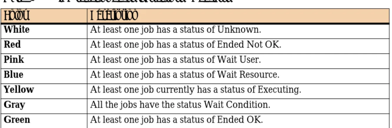
■ If all descendant nodes have the same status, the title bar of the high-level node is the same color as its descendants.
■ If the descendant nodes have different statuses, the color of the high-level node is as described in Table 4. In this case, vertical color bars at the bottom of the node indicate the proportional status distributions of descendant nodes.
Red Ended Not OK Job processing finished unsuccessfully.
Example: Agent platform on which the job was running was changed to disabled by a user.
White Unknown Communication with the Agent platform was interrupted.
Purple Not in AJF Job is not in the Active Jobs file. This status is displayed only in archived ViewPoints.
EXAMPLE
The following application node has some jobs that have Ended OK and some that have Ended Not OK.
Table 4 High-level node status colors - Defaults
Color Description
White At least one job has a status of Unknown.
Red At least one job has a status of Ended Not OK.
Pink At least one job has a status of Wait User.
Blue At least one job has a status of Wait Resource.
Yellow At least one job currently has a status of Executing.
Gray All the jobs have the status Wait Condition.
Green At least one job has a status of Ended OK. Table 3 Job status indicated color (part 2 of 2)
Recognizing job dependencies
Examples
Table 5 presents examples of nodes.
Recognizing job dependencies
Job dependencies are established through prerequisite conditions (In prerequisite conditions and Out prerequisite conditions) in job processing definitions (see the
CONTROL-M Concepts Guide).
Job dependencies in the flow diagram are represented by lines and arrows connecting job nodes, for example . (These lines can even indicate dependencies between jobs in different CONTROL-Ms.) The direction of arrows at the ends of the lines indicates the flow direction (predecessor and successor relationship) of the connected nodes. Dotted lines between two jobs indicates a conditional link between the two jobs (for example, optional In conditions defined using OR logic).
NOTE
Emergency jobs are not considered when determining the basic color of a node.
The node color of a table containing a scheduling group is determined by both the status of the jobs in the table and the status of the scheduling group itself. The title bar display color is the color representing the greatest degree of urgency.
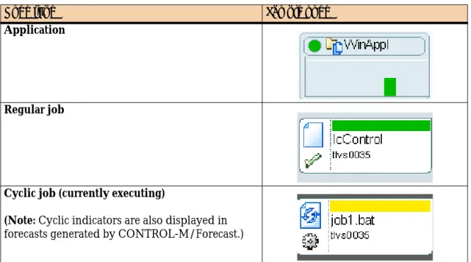
Table 5 Sample node types
Node type Sample node
Application
Regular job
Cyclic job (currently executing)
(Note: Cyclic indicators are also displayed in forecasts generated by CONTROL-M/Forecast.)
Adjusting the display
Chapter 2 Working with CONTROL-M/Desktop and CONTROL-M/EM 37 An arrow without a connecting line at the top or bottom of a node indicates one of the following condition types:
■ Arrow at the top — a manual In prerequisite condition. This condition does not get added automatically by another job, but rather must be added manually (see “Manually indicating satisfied conditions” on page 234).
■ Arrow at the bottom — The Out prerequisite condition has no corresponding In condition or job dependent upon the condition.
In CONTROL-M/EM, the connecting lines between conditions are ■ green —condition exists (active)
■ black — condition does not exist yet (inactive)
Adjusting the display
You can adjust the CONTROL-M/Desktop and CONTROL-M/EM display.
Returning panes to their original positions
You can adjust and move panes in the window by clicking and dragging.
To return panes to their original positions
Choose View => Dockable Windows => Reset to Default Layout.
Changing the data display format
You can choose from the following the data display formats: ■ flow diagram
■ list
■ Gantt chart (available only if CONTROL-M/Forecast is installed)
To change the data display formats
Displaying dependency names in a node
For more details about the Gantt chart, see Chapter 26, “Planning production with CONTROL-M/Forecast.”
Displaying dependency names in a node
By default prerequisite conditions are not displayed in the flow diagram; only the dependencies they define are indicated, by the lines and arrows running between nodes. However, you can customize the defaults so that the flow diagram also displays prerequisite conditions as condition nodes. This view is most useful when viewing a small number of jobs.
Figure 3 Condition node in the flow diagram
To display (or hide) job dependency nodes
1
With the flow diagram displayed, choose Tools => Options.2
Select the Links pane in the Flowdiagram Options dialog box, and then select (or clear) the Display condition nodes check-box.Focusing on different level nodes (stepping in and stepping
out)
You can choose to view only one particular hierarchy node level in the definition
TIP
To see dependency names for a particular node, you do not need to display dependency name nodes in the flow diagram. Instead, click a top or bottom arrow of the connecting line between nodes to flash the dependency names.
Performing other display adjustments
Chapter 2 Working with CONTROL-M/Desktop and CONTROL-M/EM 39 Changing to a higher level (for example, from Job level to Group level), is called stepping out; changing to a lower level (for example, from Group level to Job level), is called stepping in.
To change the display to different node level in the flow diagram
In the pop-up menu for the entity, choose■ Step In — to display a lower node level ■ Step Out — to display a higher node level
Performing other display adjustments
Table 6 describes a number of other display adjustments you can perform:
Table 6 Additional display adjustments (part 1 of 2)
Adjustment Step
to display or hide sub-nodes (expand or collapse the display)
Choose Collapse or Expand from the selected node’s pop-up menu. (You can select multiple nodes and then perform a single Expand or Collapse operation.)
Tip: This operation is not available when condition nodes are displayed. In this case, use the Step In (or Step Out) operation to display different hierarchy levels.
to display a node’s job processing definition (or scheduling group)
Double-click the node in the navigation tree or the flow diagram.
Filtering the jobs displayed in a CONTROL-M/Desktop draft
Filtering the jobs displayed in a CONTROL-M/Desktop draft
By default, all the jobs in the current draft are displayed, but CONTROL-M/Desktop enables you to filter which job are displayed.
To filter jobs displayed in the draft
1
In CONTROL-M/Desktop, choose View => Filter.2
In the Filter dialog box, define selection criteria for the filter. An AND relationship applies to multiple criteria; a job must satisfy all specified criteria to match.When defining criteria, consider the following points:
■ Most fields correspond to fields in the job editing form. For a description of the fields, see the CONTROL-M Parameter Guide.
■ Certain fields correspond to values for CONTROL-M parameters (for example,
August is a value for parameter MONTHS). To specify such criteria, set the value to true (for example, August = true).
■ The LIKE operator treats ∗ and ? characters in the value as wildcards; the = operator treats ∗ and ? characters in the value as literals.
(CONTROL-M/Desktop only) to change the
hierarchical arrangement of displayed data, between application hierarchy and scheduling table hierarchy
In CONTROL-M/Desktop, choose View => Hierarchy and then choose either the Application/Group/Job hierarchy or the Data Center/Scheduling Table/Job hierarchy.
Note: If you change the hierarchy when displaying data in list format, the components that are displayed depend on the node you select in the navigation tree
(In the List format in CONTROL-M/Desktop only) to alternate views between a hierarchy view and a job list view
1. With the List format displayed in CONTROL-M/Desktop, select Job List or Hierarchy List in the selection field in the CONTROL-M/Desktop toolbar.
2. To display different components in the hierarchy list or the job list, select appropriate node in the navigation tree.
Note: For an item selected in the tree view, the
■ hierarchy view shows all CONTROL-Ms, applications, groups and jobs, in hierarchical order
■ job list view shows all related jobs, in no hierarchical order Table 6 Additional display adjustments (part 2 of 2)
Arranging the CONTROL-M/Desktop flow diagram display
Chapter 2 Working with CONTROL-M/Desktop and CONTROL-M/EM 41
3
In the Action area, select how the criteria should be applied to the draft:■ Only jobs matching the specified criteria should currently be included in the filter (Set Matching jobs to be the current filter). This option is especially useful when no other criteria are currently applied or you want to override previously applied criteria.
■ Jobs matching the new criteria should be added to or removed from the current filter. These options are especially useful for adjustments when other criteria are currently applied criteria. The Remove matching jobs from the current filter option is also useful for defining criteria for exclusion rather than inclusion.
■ The full draft should be displayed (that is, the filter should be nullified).
4
Click OK to filter the draft according to the specified criteria.Draft filters are not saved for future use. When you close the draft, the filter definition is lost.
Arranging the CONTROL-M/Desktop flow diagram display
In CONTROL-M/Desktop, after you have performed many changes to the flow diagram, (for example, adding or modifying job dependencies), you might want to have CONTROL-M/Desktop rearrange the flow diagram to more neatly display the job flow.
To arrange the display
In CONTROL-M/Desktop, right-click anywhere in flow diagram (except on a job node), and select Arrange All from the menu.
TIP
Because the relationship between multiple criteria specified in the dialog box is AND, to create criteria using an implied OR relationship, do the following steps:
1. Define the first criterion or first set of AND criteria, and select Set Matching jobs to be the
current filter.
2. Then, define an OR criterion (or set of criteria, if they have an AND relationship between them), and select Add matching jobs to the current filter. This set is added to the filter (implying an OR relationship between it and the previous set). Repeat this step as needed.
Changing click and drag in CONTROL-M/Desktop to define dependencies
Changing click and drag in CONTROL-M/Desktop to define
dependencies
Normally, you click and drag the mouse to select items. In CONTROL-M/Desktop, however, you can also click and drag between nodes in the flow diagram to establish dependencies (for details, see “Defining job dependencies by using the flow diagram” on page 109). Therefore, before performing a click and drag, you must let
CONTROL-M/Desktop know your purpose, by selecting the appropriate node.
To set the mode of click and drag so that it performs node selection or
dependency definition
Do one of the following actions:
■ To set the flow diagram to Selection mode (so you can select multiple nodes), click .
■ To set the flow diagram to Definition mode (so you can create dependencies), click .
Creating workspaces and loading jobs into
CONTROL-M/Desktop
In CONTROL-M/Desktop, you need to create a workspace or draft in order to load jobs and scheduling tables. You can create and open multiple workspaces on the CONTROL-M/Desktop in online, local, or forecast modes. For more information, see “Understanding workspaces” on page 50.
To create workspaces or drafts
Do one of the following:■ To create an Online workspace, choose File => New => Online Workspace. ■ To create a local workspace, choose File => New => Local Workspace.
NOTE
Navigating in the flow diagram
Chapter 2 Working with CONTROL-M/Desktop and CONTROL-M/EM 43
To load jobs into your workspace
1
Choose File => Load jobs from CONTROL-M/EM.2
In the Load Jobs dialog box, select the tables and jobs, and click Load. Confirm the load if necessary.3
When the list of loaded job is displayed, close it.Navigating in the flow diagram
You can select multiple nodes, but only one of them can be your current (focused) node. You can navigate among the multiple selected nodes to make a different one your focused node.
To navigate to, and display, a node in the flow diagram
Click the corresponding node in the navigation tree or net overview.
To navigate to a predecessor or successor node
1
In the flow diagram or navigation tree, display the pop-up menu for the node and select Branch Menus. Then select Predecessor or Successor.2
In the submenu, select the target node (job, group, or condition), which is then selected and displayed as the current node.To find jobs in the flow diagram that conform to specific criteria
1
In CONTROL-M/Desktop or CONTROL-M/EM, select Edit => Find Jobs.2
In the Find Jobs dialog box, fill in the criteria (you can specify pattern-matchingstrings in certain fields). An AND relationship applies to multiple criteria; a job must satisfy all specified criteria to match.
3
To save the specified Find criteria for future use, choose Presets => Save and assign a name in the Save Preset dialog box, and click OK.4
In CONTROL-M/Desktop, click Select All to select all nodes matching the criteria, or click Find Next to select the first node that matches the criteria, and click Find Next again to select the next node that matches the criteria. In CONTROL-M/EM, click Find to select all nodes matching the criteria.Identifying predecessor and successor jobs
To change the focus (navigate among multiple selected nodes)
Click the appropriate navigation button (First), (Previous), (Next), or (Last), or use the View => Toggle Selection menu.
Identifying predecessor and successor jobs
Using the Network Neighborhood feature, you can identify predecessor andsuccessor jobs of a selected job. In CONTROL-M/EM, this feature also generates a list of jobs and displays their details, and you can perform other operations on the list.
To list predecessor or successor jobs and their details
1
In the flow diagram, expand all relevant group nodes so all jobs to be included are visible. Ensure that Condition nodes are not displayed.2
In the flow diagram or the navigation tree, select the relevant job or scheduling group node.3
In the View menu, choose Neighborhood.4
In the Network Neighborhood dialog box, specify the following information: ■ In the Direction field, select the node relationship:— To identify nodes branching in all directions from the selected node, select Radial.
— To identify the predecessor nodes of the selected node, select Predecessor. — To identify the nodes dependent on the selected node, select Dependent. — To identify the predecessor and dependent nodes above and below the
selected node, select Direct Relationship.
■ In the Radius field, specify the number of nested node levels (not number of nodes) to branch out from the selected node. Valid values: 1-99999.
5
Click Find to select the applicable job nodes in the flow diagram. (The number of applicable job nodes is listed in the dialog box.)NOTE
To navigate directly to a predecessor or successor node without generating detail lists, use the branch menus options. For details, see “To navigate to a predecessor or successor node” on page 43.
Printing the flow diagram
Chapter 2 Working with CONTROL-M/Desktop and CONTROL-M/EM 45 In CONTROL-M/EM, a display area opens at the bottom of the dialog box and displays the list of those jobs and their details.
6
Either close the dialog box or do one of the following:■ In CONTROL-M/Desktop, to save the data in a report, click Save Report and fill in the details.
■ While the Network Neighborhood details list is displayed in
CONTROL-M/EM, you can perform the following tasks on that list.
Printing the flow diagram
BMC Software recommends that you perform a Print Preview before printing the flow diagram. When previewing a printout, the following hints might be useful: ■ Marks on the rulers at the left and top areas of the Print Preview window, which
are designed to help you locate nodes, indicate relative distance (not inches or centimeters).
■ Columns are labeled alphabetically from left to right, beginning with A. Rows are labeled numerically from top to bottom, beginning with 0.
TIP
If the details display area does not open in CONTROL-M/EM, click Details (which alternately displays and hides this display area).
Task How to
display or hide an item count at the bottom of the Details list
Click Item Count in the pop-up menu for any job listing.
locate a listed job in the flow diagram Click Find in the pop-up menu for the job listing. open the Job Editing form for a listed job Double-click the job listing.
export the details of the listed jobs to a comma-delimited (CSV) file
Click Export to File in the pop-up menu for the job listing.
create (and view) a text report containing the details about the listed jobs
Click Create Report to save this information as a file. (To open the saved report in your default text editor, click Show Report.)
display the listed jobs in their own ViewPoint
Click Open ViewPoint. For information on these ViewPoints, see “Properties of ViewPoints based on dependent jobs” on page 227.
Changing your password
■ Pages are labeled as follows:
— Alphabetic labels indicate the horizontal sequencing. — Numeric labels indicate the vertical sequencing,
■ You can include the rulers in the printout.
■ You can include an index of displayed nodes (only when rulers are also printed). ■ You can print the entire flow diagram or a selected page range.
Changing your password
When your password is soon due to expire, the login dialog box of the CONTROL-M windows (CONTROL-M/Desktop, CONTROL-M/EM, CONTROL-M Reporting Facility, and CONTROL-M Configuration Manager) will display fields that enable you to change your password.
To change your password at any other time, you must issue the request through the CONTROL-M/EM or CONTROL-M/Desktop windows.
Password changes made in one application window (for example
CONTROL-M/EM) automatically apply to the other application windows.
To change your password
1
If the change password fields are not already displayed, in the CONTROL-M/EM or CONTROL-M/Desktop window, choose Tools => Change Password.2
Fill in your current and new passwords, and then confirm the new password.3
Click OK.EXAMPLE
■ B.A corresponds to the first column on the second page horizontally. ■ 3.2 corresponds to the second row on the third page vertically.
NOTE
Alternatively, you can change passwords using the User Authorizations window, but this is generally not recommended unless you are changing other password criteria, or changing the passwords for other users. For more information, see the CONTROL-M Administrator Guide.
Part 2 47
2
Part
Part 2
Defining the production
environment
This part presents the following topics: Chapter 3
Introduction to defining the production environment . . . 49
Chapter 4
Defining how jobs should run . . . 53
Chapter 5
Organizing and managing jobs in scheduling tables . . . 113
Chapter 8
Using predefined calendars to schedule jobs . . . 133
Chapter 9
Setting up templates for standardized job definition . . . 141
Chapter 10
Creating and updating many jobs at once . . . 147
Chapter 11
Setting up definitions for periodic statistics collection . . . 155
Chapter 11
Setting up definitions for periodic statistics collection . . . 155
Chapter 15
Chapter 3 Introduction to defining the production environment 49
C h a p t e r
3
3
Introduction to defining the
production environment
This chapter presents the following topics:
Defining the production environment . . . 49 Understanding workspaces . . . 50 Where to go from here. . . 50
Defining the production environment
Your largest and most fundamental task when you define the production
environment is defining appropriate job processing definitions, which CONTROL-M uses to control job processing and handling. This book describes how to define job processing definitions by using CONTROL-M/Desktop (you can also define job processing definitions by using batch job creation utilities).
To define job processing definitions, you should be familiar with the concept of workspaces.
Understanding workspaces
Understanding workspaces
When you define job processing definitions in CONTROL-M/Desktop, you can work in one of the following workspaces:
■ Local workspace —enables you to work locally. You can load jobs from the CONTROL-M/EM database into your local workspace, in which case you are granted exclusive access over the jobs. When you save your work, the definitions are saved in a draft file that you can later reopen in the local workspace.
For changes to be used in production, they must be written to the
CONTROL-M/EM database and uploaded to the CONTROL-M database. ■ Online workspace — enables you to work on the CONTROL-M/EM database.
When you load jobs from CONTROL-M/EM into an online workspace, you are granted shared access over the jobs. When you perform a save, the work is saved directly in the CONTROL-M/EM database. To be used in production, changes must be uploaded to the CONTROL-M database.
Regardless of which workspace you are working in when you start
CONTROL-M/Desktop, you can change workspaces (or activate the Scheduling Table Manager) at any time.
Where to go from here
Review the following list, and proceed to the appropriate chapters.
■ To define or update jobs, and place them into the appropriate databases, proceed to Chapter 4, “Defining how jobs should run.”
NOTE
■ In CONTROL-M/Desktop, you can also use an interface called the Scheduling Table Manager to directly access and modify jobs in the CONTROL-M/EM database. In this case, you are not working in a workspace.
■ If the Forecast add-on is installed, you can work in a special purpose workspace called the Forecast workspace.
NOTE
These guidelines assume that you are already familiar with the information in Part 1 of this book. If you are not, review the instructions for starting and navigating in