This equipment is designed to be installed and serviced by security and lock industry professionals.
Service Company, Put Contact Information Here: Company Name:
Service Number:
Access system programming: This access system possesses serial com-munications capability and can be managed as part of an overall access control system with Hub Manager ProfessionalTMsoftware. See the inside cover for system requirements.
Optional Keypad Programming:The prox.pad plus unit can be pro-grammed manually using the keypad on each unit and without the use of a personal computer (PC) and software. This manual contains the optional key-pad programming instructions. Keykey-pad programming can be helpful to get a door or doors up and running prior to having the availability of the host com-puter. In all cases, the personal computer programming options supersede the keypad programming options.
prox.pad
TMplus Access
System Installation/
Programming Manual
(part number HUBSWR includes software installation instructions) PC Hardware Requirements
• IBM-compatible Pentium-class computer • 30MB available hard disk space
• VGA monitor or better, 800 x 600 resolution recommended • CD-ROM or DVD-ROM drive
• Mouse
Operating System List
Table of Contents
Chapter 1: Introduction
1.1 About this Manual ... 1-1 1.2 Safety Warnings and Cautions... 1-1 1.3 Design Change Disclaimer... 1-1 1.4 Reproduction Disclaimer... 1-1 1.5 Technical Support-Service Company... 1-1 1.6 Technical Support-End User... 1-1 1.7 Warranty... 1-2 1.8 Items Supplied from the Factory ... 1-3 1.9 Items the Installer Must Supply... 1-3 1.10 General Description... 1-4 1.11 prox.pad plus Operation ... 1-6
Chapter 2: Installation
2.1 Installation Configurations... 2-1 2.2 Other Installation Considerations... 2-2 2.2.1 Power Supply/Current Requirements ... 2-2 2.2.2 Gang Box and Mounting ... 2-2 2.2.3 Mounting the Unit on Metal... 2-2 2.2.4 RF Interference ... 2-2 2.3 Checking the Cables... 2-3 2.4 Mounting the prox.pad plus Unit ... 2-7 2.4.1 Performing a Wall Mounted Installation.. 2-7 2.4.2 Performing a Glass Mounted Installation. 2-9 2.4.3 Performing a Secure Installation ... 2-11 2.5 Inserting Circuit Boards... 2-15 2.6 Defaulting prox.pad plus Memory... 2-16
Chapter 3: Wiring
3.1 Wiring the prox.pad plus Unit...3-1 3.1.1 Wiring the Door Contact Input...3-1 3.1.2 Wiring the AUX Relay for Use as Alarm Shunt ...3-3
3.1.2.A Wiring the Alarm Shunt Relay...3-3 3.1.3 Wiring the AUX Relay for Use as Forced Door...3-5
3.1.2.A Wiring the Forced Door Relay ...3-5 3.1.4 Wiring the AUX Relay for Use as
Propped Door...3-7 3.1.3.A Wiring the Propped Door Relay ...3-7 3.1.5 Wiring the REX Switch (Request to Exit) ..3-9 3.1.6 Wiring the Main Relay...3-11 3.2 prox.pad plus Communications ...3-13 3.3 Networking Multiple prox.pad plus Units
Together ...3-14 3.4 Testing the prox.pad plus ...3-16 3.4.1 Testing the Controller/Keypad...3-16
Chapter 4: Programming
4.1 Programming Overview ...4-1 4.1.1 Programming from the Keypad...4-2 4.1.1.A Master Code (User Location #1) ...4-2 4.1.1.B Supervisor Code (User Location #2).4-3 4.1.1.C Master Code and Supervisor Code Special Features...4-3 4.1.1.D prox.pad plus Default Settings ...4-4 4.1.1.E Resetting the Master Code and
System Defaults Only ...4-6 4.1.1.F Erasing Entire Memory/Resetting System Defaults...4-7
4.2 Programming Users... 4-8 4.2.1 Adding New or Changing Existing
Codes/Cards ... 4-8 4.2.2 Programming Code and Card Options .... 4-8 4.2.2 Programming User Types... 4-9
4.2.2.A Programming User Data,
Command 50, Full Format ... 4-10 4.2.2.B Quick Program Feature... 4-11 4.2.2.C Programming Code ONLY Use ... 4-11 4.2.2.D Programming Code AND Card
Use ... 4-11 4.2.2.E Programming Card ONLY Use ... 4-12 4.2.2.F Programming Code OR Card... 4-12 4.2.3 Batch Load Cards by Presentation... 4-13 4.2.4 Enabling/Disabling Users Command ... 4-14 4.2.5 Batch Load Cards Manually (without
presentation) ... 4-15 4.2.6 Block Delete of Users ... 4-16 4.2.7 Deleting Users ... 4-16 4.3 Programming Outputs... 4-17 4.3.1 Changing the Lock Output Time... 4-17 4.3.2 Assigning Outputs ... 4-17 4.3.3 Setting Propped Door Output Time ... 4-19 4.3.4 Setting Forced Door Output Time... 4-19 4.4 Programming Keypad Options and
Parameters... 4-20 4.4.1 User Lockout Option... 4-20 4.4.1.A Lockout By Location... 4-20 4.4.1.B Lockout By Group... 4-21 4.4.2 TimeZone/Holiday Features... 4-22 4.4.2.A Midnight Crossing TimeZones... 4-23 4.4.2.B Holidays ... 4-24 4.4.2.C Daylight Savings Time ... 4-24 Table of Contents
4.4.2.D Leap Year ...4-25 4.4.2.E Time/Date Set...4-25 4.4.3 Turning Visual LED/Keypress Indicator ON/OFF ...4-25 4.4.4 Turning Audio Keypress Feedback
ON/OFF ...4-26 4.4.5 Error Lockout ...4-27 4.4.6 Timed Anti-Passback ...4-28 4.5 Using the Printing Features...4-30 4.5.1 Selecting Transaction Log Information...4-30 4.5.2 Printing a Transaction Log...4-31
4.5.2.A Programming a Transaction Dump Code ...4-32 4.5.2.B Printing a Transaction Log
Manually...4-32 4.5.2.C Erasing a Transaction Log...4-33 4.5.2.D Printing a Programmed Users List....4-33 4.6 Programming Commands ...4-35
Chapter 5: Troubleshooting
5.1 Before Calling IEI ...5-1 5.2 Flow Charts ...5-4 5.3 Performing Power Supply Integrity Test...5-6 5.4 Correcting Possible Water Problems...5-9 5.4.1 Silicone...5-9 5.4.2 Wire Run ...5-9
Chapter 6: Miscellaneous
Information
6.1 Customer Service Policy...6-1 6.2 RMA Policy ...6-2
List of Illustrations
Figure 1-1 RS-485 Configuration...1-5 Figure 1-2 LAN/WAN Configuration...1-5 Figure 2-1 prox.pad plus Wiring Harness...2-3 Figure 2-2 Identifying Pin Connectors ...2-4 Figure 2-3 Performing a Wall Mounted
Installation ...2-8 Figure 2-4 Performing a Glass Mounted
Installation ...2-10 Figure 2-5 Performing a Secure Installation ...2-12 Figure 2-6 Removing/Inserting Printed Circuit
Board ...2-15 Figure 2-7 Program Button Location on Main
Circuit Board ...2-17 Figure 3-1 Wiring the Door Contact Input ...3-2 Figure 3-2 Wiring the Aux Relay for Alarm
Shunt Operation...3-4 Figure 3-3 Wiring the Aux Relay for Forced
Door Alarm...3-6 Figure 3-4 Wiring the Aux Relay for Propped
Door Alarm...3-8 Figure 3-5 Wiring the REX Switch ...3-10 Figure 3-6 Electric Strike (Fail Secure)
Wiring Diagram ...3-11 Figure 3-7 MagLock (Fail Safe) Wiring
Diagram...3-12 Figure 3-8 Connecting the prox.pad plus to a
PC COM Port...3-13 Figure 3-9 Connecting the prox.pad plus to a
Network ...3-14 Figure 3-10 Networking Multiple prox.pad
List of Tables
Table 1-1 prox.pad plus Specifications ... 1-7 Table 2-1 prox.pad plus Pin Connections... 2-5 Table 2-2 IEI-Supplied Parts/Optional Items.. 2-6 Table 4-1 prox.pad plus Default Settings... 4-4 Table 4-2 prox.pad plus LED Indicators/
Sounder Operations... 4-5 Table 4-3 prox.pad plus User Types ... 4-9 Table 5-1 Troubleshooting Chart... 5-2
Chapter 1:
Introduction
1.1 About this
Manual
This manual is designed for installers and users of the International Electronics prox.pad plus Access System.
1.2 Safety
Warnings and
Cautions
When handling the main printed circuit board, to guard against possible static discharges, touch a grounded object BEFORE touching the prox.pad plus unit. Static shock can render the product unusable.
1.3 Design
Change
Disclaimer
Due to design changes and product improvements, information in this manual is subject to change without notice. IEI assumes no responsibility for any errors that may appear in this manual.
1.4 Reproduction
Disclaimer
Neither this manual nor any part of it may be repro-duced, photocopied, or electronically transmitted in any way without the written permission of IEI.
1.5 Technical
Support-Service
Company
To contact IEI’s Technical Support department, call 1-800-343-9502 between 8:00 a.m. - 7:00 p.m. (Eastern Standard Time), Monday through Friday. Questions can also be submitted through our website at www.ieib.com.
1.6 Technical
Support-End User
1.7 Warranty
International Electronics Inc. (IEI) warrants its prod-ucts to be free from defects in material and workman-ship when they have been installed in accordance with the manufacturer’s instructions and have not been modified or tampered with. IEI does not assume any responsibility for damage or injury to person or prop-erty due to improper care, storage, handling, abuse, misuse, normal wear and tear, or an act of God. IEI’s sole responsibility is limited to the repair (at IEI’s option) or the replacement of the defective product or part when sent to IEI’s facility (freight and insurance charges prepaid) after obtaining IEI’s Return Material Authorization. IEI will not be liable to the purchaser or any one else for incidental or consequential dam-ages arising from any defect in, or malfunction of, its products.Except as stated above, IEI makes no warranties, either expressed or implied, as to any matter whatsoever, including, and without limitation to, the condition of its products, their merchantability, or fitness for any particular purpose.
Warranty Periods Are:
1 Year PowerKey
2 Years Door Gard & Secured Series Products
2 Years prox.pad and prox.pad plus
2 Years LS Series
2 Years Glass Break
5 Years ‘e’ Series Keypads
2 Years Network Gateway
All products have date code labeling to determine the warranty period. A 90-day grace period is added to all products to account for shelf life.
1.8 Items Supplied
from the Factory
The following items are supplied from the factory with the initial prox.pad plus shipment.
• Controller with Keypad, Faceplate, Request to Exit (REX) button (also called the “Filler Piece”), three Wire Harnesses, and various installation Screws.
1.9 Items the
Installer Must
Supply
For each initial prox.pad plus unit installation, the installer must supply the following items:
• The prox.pad plus unit works with these four types of cards:
– Prox Card II – IsoProx II – Duo Prox II – Proxkey FOB
• a filtered and regulated 12VDC power supply • the appropriate installation electrical tools • the recommended remote antenna cable
[ALPHA 1174C (22AWG) 4-wire, stranded] (this is re-quired ONLY if you choose to remote the antenna a maximum 10 feet away from the keypad/controller) • RS-485 cable (24AWG), shielded, two twisted-pair
tele-phone cable with a shunt capacitance of 16 pF/Ft (required only when using software)
• power supply cable (18AWG-22AWG) 2-wire stranded (depends on distance)
• door lock cable (18AWG-22AWG) 2-wire stranded (de-pends on distance)
• door monitor cable (18AWG-22AWG) 2-wire stranded (depends on distance)
• REX cable (if using remote switch) 2-wire stranded • For PC programmed and managed systems (not
re-quired in applications where programming is accom-plished at the prox.pad plus keypad):
– Hub Manager™ Professional access control soft-ware version 5 or higher with PC meetings re-quirements shown on inside of front cover – RS-232 to RS-485 interface installed on the PC
COM port, which converts RS-232 communica-tions to RS-485 (IEI model IEI232-485; part number 0295093)
1.10 General
Description
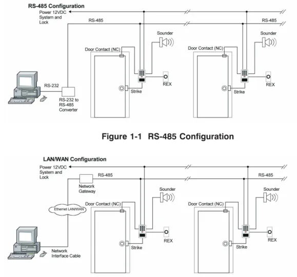
The prox.pad plus unit is a single door access system that is programmed and managed from a personal computer using Hub Manager Professional software (version 5 or higher). The prox.pad plus unit is equipped with RS-485 communications, which allow up to 32 prox.pad plus doors to be networked together. Connectivity options include direct connection to a personal computer (PC) com port using the IEI 232 to 485 converter as well as LAN/WAN connectivity using the network gateway for IEI access systems.
The prox.pad plus unit is unique in that no separate controller is needed and there is no need to run cables from a reader to a control. The unit is self-contained and includes built in HID proximity and IEI keypad readers as well as the controller.
Separate options include the prox.pad plus power sup-ply, which provides additional security with a tamper circuit that prevents lock release should the case be pried open. In addition, the prox.pad plus unit can be programmed manually with the unit’s keypad. Impor-tant features include:
• Managed with Hub Manager™ Professional access soft-ware
• 32 doors per site
• No separate control to install • Eliminate costly reader wiring • 2000 users per door
• 2000 event audit trail • Integrated-HID proximity • Card, code, card and/or code • Locate proximity 10 ft from control • Indoor and outdoor
• Glass mount kit • RS-485 network
• LAN/WAN connectivity option • Option for data collection with PDA • Door monitor
• Main relay for lock
• Programmable auxiliary relay • Local sounder for alerts
Figure 1-1 RS-485 Configuration
Figure 1-2 LAN/WAN Configuration
NOTE: prox.pad plus RS 485 communications—The prox.pad plus unit communicates with the host com-puter via the IEI RS232-RS485 interface (part number IEI232-485). For additional details see pages 3-13 to 3-15. For wire specifications, see page 1-7.
NOTE: Use with IEI Secured Series™ (Hub, Hub Max, Hub MiniMax) Networks—The RS 485 network char-acteristics for the prox.pad plus unit are different than those of IEI’s Secured Series access systems. This means the prox.pad plus unit can operate in the same system as Secured Series controllers but not on the same physi-cal network. Hub Manager Professional software (v5 or higher) can manage Secured Series doors and prox.pad plus doors (and LS doors as well), but these door controllers cannot be “connected” to the same network and network wires. Secured Series commu-nication is RS-232; prox.pad plus commucommu-nication is RS-485. These communication protocols are different. However, the ability of the Hub Manager Professional software to set up multiple local and LAN/WAN sites makes this an advantage rather than a problem.
1.11 prox.pad plus
Operation
Once installed and programmed successfully, the prox.pad plus controller stores all transactions and controls all outputs. The controller receives data sent to it from the proximity reader, decides if access should be provided or not, and then energizes the door lock or not, locking or unlocking the door.
The prox.pad plus unit includes two relay outputs (located internally), an internal clock, programming keypad, and memory chips to store user information and a transaction data log.
An external IR (infrared) LED/port/transmitter at the top right of the prox.pad plus controller allows for printing of the Transaction Log and the Programmed User List to the optional IEI PDA Data Capture Device (DCD) software. Chapter 4 discusses printing reports. NOTE:IEI recommends that first-time installers test the prox.pad plus unit BEFORE actually mounting and wiring the unit to become familiar with its op-eration (see Chapter 2).
Table 1-1. prox.pad plus Specifications ELECTRICAL
Power Supply/Current Requirements
10-15 VDC, linear filtered and regulated power supply 500 mA (not including locking device or peripherals) WIRING
Remote Antenna Cable ALPHA 1174C (22AWG) 4-wire, stranded (this is required ONLY if you choose to remote the antenna 10 feet away from the keypad/controller)
RS-485 Cable 24AWG, shielded, two twisted-pair telephone cable with a shunt capacitance of 16 pF/Ft (required only when using software)
Power Supply Cable 18AWG - 22AWG 2-wire stranded (depends on distance)
Door Lock Cable 18AWG - 22AWG 2-wire stranded (depends on distance)
Door Monitor Cable 18AWG - 22AWG 2-wire stranded (depends on distance)
REX Cable (if using remote switch) 2-wire stranded MECHANICAL
Height 5.25 in (13.3 cm)
Width 2.75 in (7 cm)
Depth 1.375 in (3.5 cm)
RELAY OUTPUTS
Main Relay - Form C (switches up to 2A) Aux Relay - Form C (switches up to 2A) MONITOR INPUTS
Door Position (Normally Closed, dry contact) Request to Exit (REX, Normally Open, dry contact) 1.11 prox.pad plus Operation Chapter 1: Introduction
OTHER OUTPUTS
IR Infrared output to optional IEI DCD PDA program SOUNDER 4000 Hz, defeatable (see Table 4-2)
LEDs Bi-Color (red/green) (see Table 4-2) Yellow
COMPATIBLE PROXIMITY CARDS
All 26-bit HID card, including the following: ProxCard II, IsoProx II, Duo Prox II, and Proxkey FOB; 26-bit cards are required for manual or batch programming UNIT CAPACITY
Users 2,000 users maximum; each user can have a card/tag, a PIN code, or a card/tag plus a PIN code Transactions 2,000 transactions maximum; each transaction
includes time, date, user “slot number,” and event
Lock Time 1-255 seconds
Lock Mode Access Time or Toggle/Latch
ALARM OUTPUT One of these three events can be programmed: Alarm Shunt Relay, Forced Door Relay, or Propped Door Relay
USER ACCESS CONFIGURATIONS
Code ONLY Code AND Card Card ONLY Code OR Card
PROGRAMMABLE USER TYPES
Each user is assigned one of the following user types: 0-Toggle/latch strike
1-Normal access 2-Log Dump 3-Lockout
4-Extended unlock 5-Single use 6-Relock 7-Emergency SYSTEM USES/
INSTALLATION CONFIGURATIONS
Suitable for small installations or remote locations, indoors or outdoors
Wall mounted, glass mounted, or secure installation ENVIRONMENTAL Indoor or outdoor
Operating Temperature -31° to 150° F (-35° to 66° C)
Operating Humidity 5% to 95% relative humidity, non-condensing Table 1-1. prox.pad plus Specifications (continued)
Chapter 2: Installation
Chapter 2 supplies information about prox.pad plus installation configurations; installation considerations; and procedures for checking the cables, mounting the prox.pad plus unit, inserting circuit boards, and de-faulting prox.pad plus memory.
2.1 Installation
Configurations
It is the installer’s responsibility to determine the ap-propriate prox.pad plus installation configuration, which differs from installation to installation. These three installation configurations are possible:
• Wall mounted installation (exterior to the room to be accessed). In this configuration, a single gang electrical box can be used. Typically, the prox.pad plus unit is wall mounted (surface mounted) out-side the access area on the unsecured out-side.
• Glass mounted installation, using the four IEI-supplied pressure-sensitive adhesive pads. In this configuration, the prox.pad plus unit is affixed with the adhesive pads to the glass door or the window adjacent to the door being accessed, on the interior side of the glass. The side cut-out on the unit is used to bring the wires out of the side of the prox.pad plus case.
• Secureinstallation (or “two-stage” configuration), for higher security. In this configuration, the prox.pad plus antenna is located a maximum of 10 feet away from the controller/keypad; the con-troller/keypad is located on the secure side of the door.
2.2 Other
Installation
Considerations
Sections 2.2.1-2.2.4 describe important considerations the installer must decide upon before actually starting to install and wire the prox.pad plus unit.
2.2.1 Power Supply/Current Requirements
Power for the prox.pad plus unit must be from a mini-mum 10-15 volt DC linear, filtered and regulated power supply. It is typical for the chosen power supply to power BOTH the prox.pad plus unit and the se-lected locking device. When using one power supply for both the prox.pad plus unit and locking device, be sure to include both devices in your current require-ments calculations.
NOTE:IEI recommends that you ground the power supply to earth ground.
2.2.2 Gang Box and Mounting
For the wall mounted installation configuration, a sin-gle gang electrical box can be used. (Typically, the prox.pad plus unit is wall mounted outside the access area on the unsecure side of the door.)
2.2.3 Mounting the Unit on Metal
The prox.pad plus unit uses radio frequency to transfer power to and communicate with the proximity card or keytag. If the antenna is mounted directly on a metal building or wall, some of the energy is absorbed by the metal, resulting in less power being transmitted to the keytag; this causes reduced read range. If you must mount the prox.pad plus unit on metal, test the unit in place before permanently installing it. If read range distance is not adequate, a non-metallic spacer can be fabricated and installed between the unit’s antenna and the metal mounting surface.
2.2.4 RF Interference The prox.pad plus unit should not cause interference
to other equipment as it is designed to meet FCC guidelines. However, other devices can interfere with prox.pad plus operation.
Avoid locating the prox.pad plus unit closer than 3 feet (1 meter) to a computer monitor or television or an-other prox.pad plus unit. If you believe you are expe-riencing reduced read range due to interference, try repositioning the prox.pad plus unit, remoting the an-tenna, or relocating other nearby electrical equipment.
2.3 Checking the
Cables
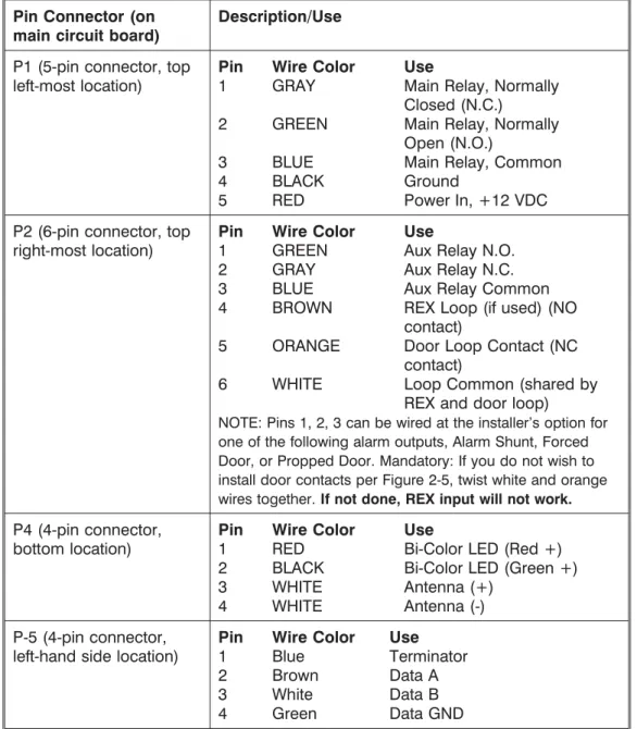
Figure 2-1 below provides a detailed illustration of the prox.pad plus wiring harness. Figure 2-2 illustrates the Pin connectors on the main circuit board; Table 2-1 describes these four Pin connectors, P1, P2, P4, and P5.
Figure 2-1 prox.pad plus Wiring Harness
P5 NOTE: P3 Not Used 1-Blue (Terminator)
2-Brown (Data A) 3-White (Data B) 4-Green (Data GND) System Power: 12VDC
Connections for remote installation of proximity antenna
For RS-485 Communications
1-Gray (Main Relay N/C) 3-Blue (Main Relay C) 4-Black (-V)
5-Red (+V
1-Green (Aux Relay N/O) 2-Gray (Aux Relay N/C) 3-Blue (Aux Relay C) 4-Brown (REX Loop) 5-Orange (Door Loop) 6-White (Loop Common)
1-Red (Bi Color LED) 2-Black (Bi Color LED) 3-White (Antenna +) 4-White (Antenna -)
)
2-Green (Main Relay N/O)
Table 2-1. prox.pad plus Pin Connectors Pin Connector (on
main circuit board)
Description/Use
P1 (5-pin connector, top left-most location)
Pin Wire Color Use
1 GRAY Main Relay, Normally Closed (N.C.)
2 GREEN Main Relay, Normally Open (N.O.)
3 BLUE Main Relay, Common
4 BLACK Ground
5 RED Power In, +12 VDC
P2 (6-pin connector, top right-most location)
Pin Wire Color Use
1 GREEN Aux Relay N.O.
2 GRAY Aux Relay N.C.
3 BLUE Aux Relay Common
4 BROWN REX Loop (if used) (NO contact)
5 ORANGE Door Loop Contact (NC contact)
6 WHITE Loop Common (shared by REX and door loop)
NOTE: Pins 1, 2, 3 can be wired at the installer’s option for one of the following alarm outputs, Alarm Shunt, Forced Door, or Propped Door. Mandatory: If you do not wish to install door contacts per Figure 2-5, twist white and orange wires together.If not done, REX input will not work. P4 (4-pin connector,
bottom location)
Pin Wire Color Use
1 RED Bi-Color LED (Red +) 2 BLACK Bi-Color LED (Green +)
3 WHITE Antenna (+)
4 WHITE Antenna (-)
P-5 (4-pin connector, left-hand side location)
Pin Wire Color Use
1 Blue Terminator
2 Brown Data A
3 White Data B
4 Green Data GND
Table 2-2. IEI-Supplied Parts/Optional Items
Quantity Description
1 Keypad/control unit assembly, with Prox Sensor, Backplate, hex socket screw
1 Filler Piece/REX Button
1 Press to Exit Label
4 Wall Anchors
4 Mounting Screws
1 Antenna Backplate for remote mounting 1 Silicone Rubber “dogbone”
4 Self-Adhering Pads (for glass mounting)
1 Installer Guide
1 CD-ROM containing instruction manuals
4 Cable Assemblies
1 Tamper Screw
Optional Items
1 Replacement Battery: Panasonic BR1225 or equivalent lots of 25 only ProxKey Keytags (IEI part number 0297301)
lots of 25 only ProxCard II Cards (IEI part number 0297401)
1 Hub ManagerTMProfessional PC Software (version 5 or higher)
2.4 Mounting the
prox.pad plus Unit
Select one of these three installation configurations, wall mount, glass mount, or secure as appropriate for this installation. Then refer to sections 2.4.1-2.4.3.
2.4.1 Performing a Wall Mounted Installation
This section provides general considerations when performing a wall mounted installation. Typically, the prox.pad plus unit is mounted on a flat, level surface (drywall, masonry, wood, etc.) exterior to the room to be accessed. A single-gang electrical box (or “back box”) can be used. Typically, the prox.pad plus unit is wall mounted outside the access area on the unsecure side of the door.
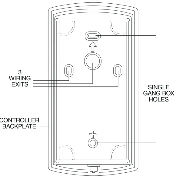
Figure 2-3 illustrates the backplate on the prox.pad plus unit used for wall mounting. Two “single-gang box” holes align with two corresponding holes in the single-gang box. A “wire” exit knockout is supplied through which the prox.pad plus wiring is pulled. A typical wall mounted installation proceeds as follows: 1. Secure a single-gang box to the desired location.
2. “Punch out” the two single-gang box connectors
on the controller backplate of the prox.pad plus unit.
3. Disconnect the controller backplate of the
prox.pad plus unit from the front keypad/control-ler. Align the two single-gang box connectors on the controller backplate over the two correspond-ing holes on the scorrespond-ingle-gang box, previously se-cured at step 1.
4. Secure the backplate to the single-gang box by
inserting/tightening two screws into the two sin-gle-gang box holes.
5. Pull the prox.pad plus wiring through the wiring exit as appropriate.
6 Connect the front keypad/controller to the back
housing.
7. Install the tamper screw into the hole at the bottom front of the enclosure using a #6 spanner bit (not included, but available from IEI).
Figure 2-3 Performing a Wall Mounted Installation
2.4.2 Performing a Glass Mounted Installation
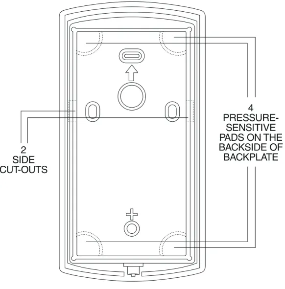
Figure 2-4 shows the four IEI-supplied pressure-sen-sitive adhesive pads and the two side cut-outs used for this installation. In this configuration, the prox.pad plus unit is affixed with the four self-adhesive pads to the glass or the glass window adjacent to the controlled door being accessed, on the interior side of the glass. One of the two side cut-outs is used to bring the wires out of the side of the prox.pad plus case.
A typical glass mounted installation proceeds as fol-lows:
1. Disconnect the back housing from the front
key-pad/controller. Remove the tape from the four self-adhesive pads on the back housing and apply the pads to the four corners of the backplate.
2. Affix the back housing to the glass door or the
glass window adjacent to the controlled door be-ing accessed, on the interior side of the glass.
3. Determine which of the two side cut-outs on the
back housing to use for the wiring and “cut out” that cut-out using the appropriate cutting tool. 4. Pull the wiring through the selected side cut-out
as required.
5. Connect the front keypad/controller to the back
housing.
6. Install the tamper screw into the hole at the bottom front of the enclosure using a #6 spanner bit (not included, but available from IEI).
Figure 2-4 Performing a Glass Mounted Installation
2.4.3 Performing a Secure Installation
In this configuration, the prox.pad plus prox sensor housing is removed from the keypad/controller and located a maximum of 10 feet away. The controller/key-pad is located inside a secure area.
1. Remove the antenna from the prox.pad plus
key-pad/controller as described below:
• Disconnect the backplate of the prox.pad plus unit from the front keypad/controller.
• When handling the main printed circuit board, to
guard against possible static discharges, touch a grounded object BEFORE touching the prox.pad plus unit. Remove the main printed circuit board by pressing the two spring tabs in the direction of the arrows as shown in Figure 2-5. Be careful with the wires.
• Pull on the main circuit board and remove Pin
connector P4 (a 4-pin connector) from the bottom of the main board. A ribbon cable now holds the main board to the keypad board. DO NOT pull this ribbon cable out of its connector! Once the main board is removed, you can access the interior of the antenna.
• Remove the antenna housing from the
key-pad/controller by pressing the labeled four secure tabs inward (see Figure 2-5) until the sensor hous-ing “pops out.”
2. Prepare the wiring and extension wiring as
fol-lows:
• Cut off the plastic end of the prox.pad plus sensor housing harness.
• Splice the recommended remote antenna cable
Alpha 1174C (22AWG), 10-foot maximum length, to the properly cut antenna cable using standard electrical techniques.
KEYPAD/ CONTROLLER
3. Mount the antenna backplate in a vertical orien-tation and secure it to the wall through the two screw holes using two IEI-provided screws. En-sure that the two “weep holes,” provided to re-move possible moisture, are positioned on the bottom. The wiring exits in the antenna backplate. (Four external cut-outs on the antenna backplate match the four spring-loaded tabs on the an-tenna.)
NOTE: Two side cut-outs are furnished on the antenna backplate for the wiring, if the installation does not permit the wiring to run through the wall. These must be “cut out” to be used.
• Once the antenna backplate is mounted properly,
align the antenna to the backplate and connect the antenna to the antenna backplate. The large tab in the center of the antenna assembly must be broken off before being attached to the antenna backplate.
4. Run the antenna wiring back to the secure
key-pad/controller and connect it to the main circuit board, using the 10-inch 4-wire harness (red, black, white, and white) that you plug into con-nector P4 on the controller board. Connect the red wire of the antenna to the red wire of the P4 harness, etc. Seal the wire holes with silicone. 5. Select “Filler” or “Request to Exit” (REX) operation
as follows:
• If you elect to use the filler piece as a REX switch, return to the keypad/controller and break off two tabs on the filler piece as illustrated in Figure 2-5. The filler piece replaces the antenna on the front of the keypad/controller for secure installations.
• If the filler piece is not to be used as a REX switch, DO NOT remove the two tabs.
• Select “Filler or “REX” operation and affix the appropriate IEI-provided label to the filler piece.
For Filler operation, no tabs are broken off the filler piece, which merely sits in place of the re-motely located antenna, once the main circuit board and cabling are replaced.
For REX operation, break off the labeled tabs, which allows a spring-loaded tab to engage the REX switch on the main circuit board and open the door.
• Replace the main circuit board into the
key-pad/controller and Pin connector P4 to the main circuit board.
• Connect the front keypad/controller of the unit to the back housing.
• Secure with a hex socket screw using the supplied hex wrench, or secure with a tamper screw (optional tool required).
2.5 Inserting
Circuit Boards
If it proves necessary to remove or insert the main circuit board from/into the prox.pad plus control-ler/keypad, follow the steps below.
1. Disconnect the back housing of the prox.pad plus unit from the front keypad/controller.
2. (When handling the main printed circuit board, to guard against possible static discharges, hold the board by its edges with one hand and then touch a grounded object BEFORE touching the prox.pad plus unit.) Remove the main printed circuit board by pressing the two spring tabs in the direction of the arrows as shown in Figure 2-6. Be careful with the wires.
Figure 2-6 Removing/Inserting Printed Circuit Board
3. Fold up the main circuit board and remove the P4 connector (a 4-conductor harness) from the bot-tom of the board.
4. To re-insert, replace the main circuit board into the keypad/controller and the P4 connector to the main circuit board.
5. Connect the keypad/controller to the back
hous-ing.
2.6 Defaulting
prox.pad plus
Memory
If necessary, the prox.pad plus main memory can be defaulted. This procedure explains how to do this; see Figure 2-7 on the next page. You would default the memory, if, for instance, static discharges have cor-rupted the prox.pad plus unit, during shipping or in-stallation. You can also do this if you have simply forgotten the Master Code and you need to enter pro-gram mode.
With the power ON, remove the case from the prox.pad plus front controller/keypad to access the main circuit board. (For a visual reference of the main printed circuit board and the related pin connectors, see Figure 2-2. Table 2-2 describes these pins in detail.)
(When handling the main printed circuit board, to guard against possible static discharges, touch a grounded object BEFORE touching the prox.pad plus unit.)
1. With the power ON, press and hold the Program
button (located on the rear side of the main printed circuit board) for two seconds.
3. Enter the following on the keypad:
46 # 00000 # 00000 # **
The yellow LED flickers for 10 seconds and then blinks slowly.
4. Once the memory set-up is complete, re-assemble the unit.
NOTE: CONNECTING DOOR LOOP
IN-PUTBefore powering up the prox.pad plus unit,
connect the Door Loops input to the “Loop Com-mon.” This prevents “Forced Door” or “Propped Door” conditions from developing upon power-up.
FORGET MASTER CODE
PCB
MASTER CODE SWITCH (PROGRAM SWITCH) (ON REAR SIDE OF PC BOARD)
CONTROLLER HOUSING
Figure 2-7 Program Button Location on Main Circuit Board
Chapter 3: Wiring
Chapter 3 provides wiring diagrams and associated procedures.
3.1 Wiring the
prox.pad plus Unit
Select one of these three wiring options, Alarm Shunt, Forced Door, or Propped Door, depending on how the prox.pad plus unit’s AUX relay is to be employed for this installation (refer to Chapter 4 for program-ming information). Then refer to sections 3.1.1- 3.1.5 as appropriate.
3.1.1 Wiring the Door Contact Input
In order for the Alarm Shunt, Propped Door, and Forced Door features to work, a door contact switch must be used. Before wiring the AUX relay, connect a door contact to the keypad. See Figure 3-1 for details. To solve the problem of people “tailgating” in behind personnel using valid access protocol, the Auto Re-Lock feature is provided. With Auto Re-Re-Lock, a long door open time can be programmed. Auto Re-Lock overrides the lock output timer, resetting the door open time as soon as the prox.pad plus unit senses that the door is open. A long door open time allows people sufficient time to carry packages from the prox-imity reader/keypad to the door and open it before the timer runs out.
No programming is required to implement this fea-ture.
After a valid access or egress, the prox.pad plus unit senses that the door switch is open and drops the main relay immediately. This disengages the lock, which locks behind the person regardless of how long it takes that person to get through the door.
NOTE:This feature requires that you use the “Door Contact” input as shown in Figure 3-1.
P5
ORANGE
WHITE
DOOR
CONTACT
(Normally Closed)
3.1.2 Wiring the AUX Relay for Use as Alarm Shunt
The Alarm Shunt Relay function may be necessary when a separate existing security system is in place. The Alarm Shunt Relay keeps an alarm panel zone from going into alarm when the door is opened, after a valid code is entered. The Alarm Shunt function is assigned to the Aux relay by default. To incorporate this feature, follow the steps below; see Figure 3-2. 3.1.2.A Wiring the Alarm Shunt Relay
1. Turn OFF power to the prox.pad plus unit, and then unlatch the keypad from the plastic housing. 2. Locate connector P2 (the 6-pin connector) on the main circuit board and plug on the 6-pin harness. (The 2-pin jumper on pins 5 and 6 of connector P2 must be removed first.)
3. Connect the 6-conductor harness to connector P2 as shown in Figure 3-2.
4. Connect the blue wire to the “Common” side of the door contact.
5. Connect the green wire to the “Normally Open” side of the door contact.
6. Make a parallel connection to the green and blue wires and run the leads to the alarm panel.NOTE: This feature requires that you use the “Door Con-tact” input as shown in Figure 3-1.
7. Restore power to the keypad and test.
P5 TO ALARM PANEL DOOR
CONTACT GOING BACK TO ALARM PANEL
TO ALARM PANEL
GREEN (N/O)
BLUE ( C )
ORANGE
WHITE
DEDICATED DOOR CONTACT (NC) BEING MONITORED BY THE prox.pad unit
Figure 3-2 Wiring the Aux Relay for Alarm Shunt Operation
3.1.3 Wiring the AUX Relay for Use as Forced Door
The Forced Door output function informs personnel that the door has been opened without authorization. By default, the Forced Door output is assigned to Audio Alert #1. To use the Aux Relay, you must first assign it. See the command below, in the second note. The Aux relay is rated to handle two amps of current at 12 VDC, and can turn ON or OFF one leg of the power to a warning device. (Warning device not in-cluded with the IEI unit.) To incorporate this feature, follow the steps below; see Figure 3-2.
3.1.2.A Wiring the Forced Door Relay
1. Turn OFF power to the prox.pad plus unit, and then unlatch the keypad from the plastic housing. 2. Locate connector P2 (the 6-pin connector) on the
main circuit board.
3. Connect the 6-conductor harness to connector P2. (The 2-pin jumper on pins 5 and 6 of connector P2 must be removed first. See Figure 3-3.)
4. Connect the green wire (NO) to V+ on the warn-ing device.
5. Connect the blue wire (C) to V+ on the power supply.
6. Connect V- from the power supply to V- on the sounder. The gray wire is not used.
7. Restore power to the keypad and test.
NOTE: To use the default 10-second Forced Door Relay time, no programming is necessary. To change this default (from 10 to 990 seconds), use command
45 # ttt # 0 # **after the unit is installed successfully; for details, see section 4.3.4.
NOTE: PROGRAMMING FOR FORCED DOOR:
To assign the Forced Door output to the Aux Relay, enter the following on the keypad:
10 # 4 # 2 # **
To disable audio alert #1, enter:
10 # 0 # 5 # **
BLUE (C) ORANGE
WHITE
P5
DEDICATED DOOR CONTACT (NC) BEING MONITORED BY THE prox.pad unit
TO POWER SUPPLY
V- V+
GREEN (NO)
Figure 3-3 Wiring the Aux Relay for Forced Door Alarm
3.1.4 Wiring the AUX Relay for Use as Propped Door
The Propped Door Relay output function informs per-sonnel that the door is being held open, or “propped” open, after a valid entry. By default, the Propped Door output is assigned to audio alert #2. To use the Aux Relay, you must first assign it. See command below. The Aux relay is rated to handle two amps of current at 12 VDC, and turns ON or OFF one leg of the power to a warning device. (Warning device not included with the IEI unit.) To incorporate this feature, follow the steps below; see Figure 3-3.
3.1.3.A Wiring the Propped Door Relay
1. Turn OFF power to the prox.pad plus unit, and then unlatch the keypad from the plastic housing. 2. Locate connector P2 (the 6-pin connector) on the
main circuit board.
3. Connect the 6-conductor harness to connector P2. (The 2-pin jumper on pins 5 and 6 of connector P2 must be removed first. See Figure 3-4.)
4. Connect the green wire (NO) to V+ on the sounder.
5. Connect the blue wire (C) to V+ on the power supply.
6. Connect V- from the power supply to V- on the sounder. The gray wire is not used.
7. Restore power to the keypad and test.
NOTE:To use the default 30-second Propped Door Relay time, no programming is necessary. To change this default (from 30 to 990 seconds), use command
44 # ttt # 0 **after the unit is installed successfully; for details, see section 4.3.3.
NOTE: PROGRAMMING FOR PROPPED DOOR:
To assign the Propped Door output to the Aux Relay, enter the following on the keypad:
10 # 3 # 2 # **
To disable audio alert #2, enter:
10 # 0 # 6 # **
BLUE (C) ORANGE
WHITE
P5
DEDICATED DOOR CONTACT (NC) BEING MONITORED BY THE prox.pad unit
TO POWER SUPPLY
V- V+
GREEN (NO)
Figure 3-4 Wiring the Aux Relay for Propped Door Alarm
3.1.5 Wiring the REX Switch (Request to Exit)
The prox.pad plus unit can be wired to monitor a remote switching device, which is intended to be in-stalled on the “secure” side of a door. The Request to Exit (REX) loop is a momentary input that engages the lock output for the same length of time for which it is programmed. This feature can be stored in the Trans-action Log for viewing as REX.
If you elect to perform a secure installation where the controller is mounted on the secure side of the door, you can use the filler piece as a REX switch. To enable the internal REX switch, enter the following program-ming command:30 # 7 # 1 # **
For other installations, a separate REX switch must be purchased.
Other REX devices can be used to include a remote button placed at a receptionist’s desk, a press-to-exit switch on the inside of a door, or a passive infrared detector, allowing free and convenient egress. The external REX feature requires no programming; simply wire the unit as illustrated in Figure 3-5. To incorporate this feature, follow the steps below:
1. Turn OFF power to the prox.pad plus unit, and then unlatch the keypad from the plastic housing. 2. Locate connector P2 on the main circuit board. 3. Plug the 6-conductor harness into connector P2.
(The 2-pin jumper on pins 5 and 6 of connector P2 must be removed first. See Figure 3-5.)
4. If you do not wish to install the door contacts per Figure 3-5, twist the white wire and the orange wires together; this is mandatory. If this is not done, the REX input will not function.
NOTE: The door contact MUSTbe closed for the REX feature to work properly.
P5 P5
(Normally Closed)
3.1.6 Wiring the Main Relay
The door lock is wired to connector P1 on the prox.pad plus main circuit board. Wiring for this 5-pin connector is described in Table 2-2, Figure 3-6 provides an Electric Strike (Fail Secure) wiring diagram, Figure 3-7 a MagLock (Fail Safe) wiring diagram. Refer to the power supply recommendations in Table 1-1 if neces-sary.
P5
Figure 3-6 Electric Strike (Fail Secure) Wiring Diagram
BLACK
(V-)
BLUE
(MAIN RELAY C)
V-V+
MAGLOCK
(FAIL SAFE)
POWER
SUPPLY
GRAY
(MAIN RELAY N/C)
RED
(V + IN)
P5
P4
P1
P3
P2
3.2 prox.pad plus
Communications
The prox.pad plus is equipped with RS-485 communi-cations with a data rate of 19200 bits/sec. This allows you to connect the unit to a personal computer (PC) either via the computer’s COM (serial) port or over a computer network to manage the system using Hub Manager Professional (version 5 or higher) software. To connect the prox.pad plus unit to a computer COM port (which is RS-232), an RS-232 to RS-485 converter is required. To connect the prox.pad plus unit via a computer network, the IEI Gateway device is required.
The maximum distance from the RS-485 device is 4,000 feet using the specified cable. NOTE: The Ter-minator wire may not be required. Figures 3-8 and 3-9 show examples of both connection types. Please see the instructions for your RS-232 to RS-485 converter or the instructions for the IEI Gateway for details about those devices. For details, refer to EIA RS-485 specifi-cations.
RS-232 RS-485
RS-232 to RS-485 Converter
To PC
COM port
ó
2-Brown (Data A) 3-White (Data B) 4-Green (Data GND) NOTE: The Terminator wire may not be required.P1 P3 P2
P5
P4
Figure 3-8 Connecting the prox.pad plus to a PC COM Port
3.3 Networking
Multiple prox.pad
plus Units Together
For multiple door applications, the prox.pad plus can be networked together. When networking prox.pad plus devices together on an RS-485 system, the prox.pad plus units are all wired in parallel. This net-working capability is available when connecting di-rectly to your personal computer’s COM port or when communicating over a computer network with the IEI Gateway. Figure 3-10 shows an example of networking multiple units together.The maximum number of de-vices on a network is 32.
RS-485
ó
To Computer Network
2-Brown (Data A) 3-White (Data B)
4-Green (Data GND) P1 P3 P2
P5
P4 IEI Gateway
Figure 3-9 Connecting the prox.pad plus to a Network
Device #1
Device #2
Door #1
Door #2
NOTE: The maximum number of devices on a single network is 32.
RS-232 to RS-485 Converter or IEI Gateway
P5
P1 P3 P2 P1 P3 P2
P5
P4
P4 2 - Brown (Data A)
3 - White (Data B) 4 - Green (Data GND)
Figure 3-10 Networking Multiple prox.pad plus Units Together
3.4 Testing the
prox.pad plus
At this point in a typical installation, it is assumed that the prox.pad plus unit has been mounted and wired successfully as described earlier and that testing can begin. IEI recommends, however, that first-time in-stallers test the prox.pad plus unit BEFORE actually mounting and wiring the unit to become familiar with its operation.
3.4.1 Testing the Controller/Keypad
1. Connect the positive (+) lead of the power supply to the V+ input on the prox.pad plus control-ler/keypad.
2. Connect the negative (-) lead of the power supply to the V- input on the prox.pad plus control-ler/keypad.
3. Turn ON the power supply.
4. Ensure that the bi-color LED (red and green) on the prox.pad plus unit lights red.
5. On the prox.pad plus controller/keypad, press: 7890 # 123456 *
If all 12 key presses are verified, the prox.pad plus unit enters the self-test mode. The bi-color LED turns green. The red LED blinks alternately with the yellow LED and then both turn OFF. Next, the sounder beeps three times, pauses, and then beeps once more. If this does not occur, attempt to enter the self-test mode again by repeating step 5.
NOTE:If you are using the IEI DCD software, you can capture the self-test data on a PDA. This data contains information about the device.
6. Enter the master code on the keypad by pressing: 1234 *
The red LED turns OFF and the green LED turns ON for five seconds while the main relay ener-gizes. To program the unit, see Chapter 4.
Chapter 4:
Programming
4.1 Programming
Overview
Chapter 4 provides information about programming the IEI prox.pad plus unit.
Optional Keypad Programming: The prox.pad plus unit can be programmed manually using the keypad on each unit and without the use of a personal com-puter (PC) and software. This chapter contains the optional keypad programming instructions. Keypad programming can be helpful to get a door or doors up and running prior to having the availability of the host computer. In all cases, the personal computer pro-gramming options supersede the keypad program-ming options.
4.1.1 Programming from the Keypad
The first step in programming the prox.pad plus unit is to place it into Program mode. You can enter Program mode with either the Master code or the Supervisor code. When the prox.pad unit is in Program mode, the yellow LED blinks slowly; when the yellow LED stops blinking and is OFF completely, the unit is no longer in Program mode. If an error is made in Program mode, the yellow LED remains steadily lighted; press*to clear the error condition and then re-enter the command. If the unit does not go into Program mode, refer to the Troubleshooting Chart in Chapter 5.
4.1.1.A Master Code (User Location #1)
The Master code is a special code stored in user location one. This code is used to enter Program mode, and has access to all programming commands.
To place the prox.pad plus unit in Program mode using the Master code, press:
99 # Master Code *
NOTE: “1234” is the default Master code, which IEI recommends that you change right away.
To change the Master code, enter:
1 # new master code * new master code * (example, 1 # 4321 * 4321 *)
4.1.1.B Supervisor Code (User Location #2) The Supervisor code is a special code stored in user location two. This code has limited access to Program mode, including commands:
• Adding/Deleting Users (commands #50, #51, #52, #53, #57, and #58)
• Enabling/Disabling Users (command #56)
• Changing Lock Output Time (command #11)
• Changing Keypad Platform Parameters 5 and 6 (command #32)
By default, user location two is empty, which means that if you need a Supervisor code, you must program one. To program a Supervisor code, press:
2 # new supervisor code * new supervisor code * (example, 2 # 5678 * 5678 *)
To enter Program mode using the Supervisor code, press:
99 # supervisor code *
4.1.1.C Master Code and Supervisor Code Special Features
The following is list of items that pertain only to the Master and Supervisor codes:
• The Master and Supervisor codes can only be pro-grammed as standard user types
• The Master and Supervisor codes can be pro-grammed as “card AND code” or “card OR code” users.
• The Master and Supervisor codes cannot be pro-grammed as “card only.”
• When either the Master or Supervisor is pro-grammed as “card AND code,” both are required to enter Program mode.
• When they are programmed for “card OR code,” only the card is required to enter Program mode.
• If the Master or Supervisor is programmed for “card OR code” and you want them to require both to enter Program mode, enable option 3 using command 30 (30 # 3 # 1 # * *).
4.1.1.D prox.pad plus Default Settings
Table 4-1 lists the default settings for the prox.pad plus unit as shipped from the factory. Subsequent sections in this chapter explain how to change these default settings or program additional functions.
Table 4-1. prox.pad plus Default Settings
Parameter Default Setting
Main Relay Lock Output
Auxiliary Relay Alarm shunt function Audio Alert #1 Forced Door
Audio Alert #2 Propped Door Master Code (user one) 1234*
Main Relay energizes for Five (5) seconds Audible Keypress Feedback ON
Propped Door Output activates after Thirty (30) seconds Forced Door Output activates for Ten (10) seconds
Table 4-2. prox.pad plus LED Indicators/Sounder Operations
LED or Sounder Visual/Audible Condition
Description
Yellow LED Slow blink Unit is in Program mode
Rapid blink Verify mode is active (checking that the last two values in sequence match) Steady Program error; to clear, press* or error
lockout
Very rapid blink Memory (eeprom) erase is in progress (commands 40/46, loop-back)
Bi-color LED Steady red Lock output deenergized
Steady green Lock output is energized (timed or latched)
Red/green alternating
Awaiting second PIN during “Card AND Code” access attempt
Green blink Auto-unlock active
Sounder Short beep (100 ms) every 2 seconds
Audio alert #2 is active
Sounder 1/2 sec on, 1/2 sec off
Audio alert #1 is active Double beep Lockout is canceled Pair of double
beeps
Lockout is activated 3 slow beeps
(250 ms), then single beep
Self-test is complete
Sounder After PIN/Card
1 single beep Valid card access 1 long beep
followed by 1 short beep
User disabled
1 long beep followed by 2 short beeps
Bad timezone
1 long beep followed by 3 short beeps
User lockout
3 rapid beeps after code entered or card presented
Code or Card is not found
4 quick beeps First-In Auto-unlock 6 quick beeps Toggle mode is active
4.1.1.E Resetting the Master Code and System Defaults Only
Entering command 40 restores the system defaults, leaving the user data and transaction log intact. This is useful if the prox.pad plus unit has experienced programming problems, or you wish to delete earlier programming.
1. Place the prox.pad plus unit in Program mode. Press:
99 # Master Code * (default is 1234)
A slow blinking yellow LED indicates that the unit is in Program mode. A steady yellow LED, in contrast, means that errors were detected during programming.
Table 4-2. prox.pad plus LED Indicators/ Sounder Operations (continued)
Error states can be cleared by pressing the asterisk * key.
2. Press:
40 # 00000 # 00000 # **
The yellow LED continues to blink slowly. 3. Press * to exit Program mode.
4.1.1.F Erasing Entire Memory/Resetting System Defaults
Entering command 46 deletes everything from the prox.pad plus memory including the user list but not the transaction log and restores the default settings. This is used as a last resort if you need to erase a specific user and could not retrieve the Programmed User List. 1. Place the prox.pad plus unit in Program mode.
Press:
99 # Master Code * (default is 1234)
A slow blinking yellow LED indicates that the unit is in Program mode. A steady yellow LED, in contrast, means that errors were detected during programming. Error states can be cleared by press-ing the asterisk * key.
2. Press:
46 # 00000 # 00000 # **
The yellow LED continues to blink slowly. 3. Press * to exit Program mode.
4.2 Programming
Users
4.2.1 Adding New or Changing Existing Codes/Cards
The most basic prox.pad plus programming is adding new codes or cards (users), or modifying existing codes or cards (users). Each user entry consists of three or four data values: a user type, a location and a keypad-PIN, and/or card.
Two methods can be used for adding new or changing existing codes/cards, (1) keypress sequences (manual entry), and (2) card presentations. Keypad PINs can be programmed only through a keypad sequence, while card PINs can be programmed manually or by presenting the card to the proximity reader at a speci-fied time during programming.
Table 4-3 lists the specific types of users that can be programmed with the prox.pad plus unit and the fol-lowing section describe the various ways to program users.
NOTE:When 26-bit cards are used and you choose to add new cards manually, the facility code MUST be entered into the unit first. The default facility code is 11. For the programming sequence used to enter the 3-digit facility code, see command 32, parameter 4 (see table in section 4.6).
4.2.2 Programming Code and Card Options
The prox.pad plus unit can be programmed to accept the four code/card combinations listed below.
• (1) Code ONLY (command 50)
• (2) Code AND Card (command 50 plus present card to proximity reader)
• (3) Card ONLY (command 50 or command 51)
• (4) Code OR Card (command 52)
NOTE:No user can have the same card and/or code PIN as another user.
4.2.2 Programming User Types
Table 4-3 identifies and describes the user types sup-ported by the prox.pad plus unit.
Table 4-3. prox.pad plus User Types
User Type Numeric ID Description
Toggle 0
Toggle users latch the lock in the unlock position. Toggle mode is indicated by 6 quick beeps and a solid green LED. Standard 1 Standard users use the lock duration
programmed in command 11.
Log Dump 2
For this user-type, the door remains locked and the Transaction Log is dumped to the DCD PDA software through the IR LED when the appropriate code is entered. This code cannot be used to gain access through the door. The log is not erased, only printed.
Lockout 3
Lockout users “lock out” other users - see User Lockout (section 4.4.1). These codes do not unlock the door.
Extended Unlock 4
Extended Unlock Users are like Standard users except they use the unlock duration programmed in command 32, parameter 3. The default unlock time is 10 seconds.
Single Use Code 5
Single Use Codes are codes that can only be used once. After the code is used, it is deleted from the keypad. To verify a Single Use is programmed, enter the sequence [5# PIN *] and this looks up the PIN and generates a 1/2 second green flash if the PIN is programmed as a single use code. If the PIN is not found, the system generates three quick beeps and increments the invalid PIN counter. If PIN is found but is not programmed as a single use code, the system does not respond at all.
User Type Numeric ID Description
Relock 6
Relock codes are used to relock the door when a toggle or auto-unlock is active. Entering 00 # prior to a relock code allows auto-unlock to be re-triggered, when First In is enabled.
Emergency 7
Emergency users are special users that cannot be locked out and cannot be disabled.
The user also uses the unlock duration programmed in command 32 parameter 3. The default unlock time is 10 seconds.
4.2.2.A Programming User Data, Command 50, Full Format
The full format of command 50 for programming user data is as follows:
50 # user-type # user location # keypad PIN * keypad PIN *
Programming a user’s card with command 50 requires that you present the card to the proximity reader after entering the final asterisk*.
A single beep from the sounder indicates that the card has been read and the data added to the user’s entry. If the yellow LED lights steadily after the card is pre-sented, it usually indicates one of two problems: (1) an improper keypress (correct by entering properly), or (2) the number entered is in use by another user (correct by employing an unused PIN and card).
4.2.2.B Quick Program Feature
A “quick program” feature has been implemented for user data, however. You only need to enter the user’s location and the keypad PIN (or present card), in the format noted below. Employing the quick feature auto-matically selects a “Normal” user access type.
user location # new code * repeat code
OR
user location # ** <present card> 4.2.2.C Programming Code ONLY Use
You can program a user Code ONLY use with com-mand 50. The program sequence is as follows:
50 # user-type # user location # new code * repeat code *
4.2.2.D Programming Code AND Card Use
The format for programming a user for both Code AND Card use is as follows:
50 # user-type #user location #
new code * repeat code * <present card> When a combination code/card user employs the prox.pad plus unit, that user can present the proximity card first at the proximity reader, or enter the code first at the prox.pad plus keypad as desired.
After the code/card user either presents the card at the reader or enters the code on the keypad, the red and green LEDs alternate. This indicates that the unit is awaiting the second part of the transaction before granting access. After the second part of the transaction is completed successfully, the bi-color LED turns solid green and the door opens.
4.2.2.E Programming Card ONLY Use
Card ONLY use can be programmed with command 50. The programming sequence is as follows:
50 # user-type # user location # ** <present card>
4.2.2.F Programming Code OR Card
Finally, you can program a user for either Code OR Card use as follows:
52 # user-type # user location # keypad PIN* keypad PIN * <present card>
4.2.3 Batch Load Cards by Presentation
Command 53 provides a simple method of program-ming a group of consecutive users by presenting the appropriate prox cards. This method of programming cards does not require any knowledge of the prox card format as long as it contains 39 bits or less of data. The format of the command is as follows:
53 # user type # start location # * * present cards one after another
The card loading stops automatically once the current user location exceeds 2000. Pressing any key on the faceplate aborts the loading process.
All users programmed through this command are setup as “Card Only” users. Any existing card or key-pad data for that user is erased prior to programming the new data. Entering the Master or Supervisor user as the first card in the sequence generates an error because the Master or Supervisor code cannot be pro-grammed as a “Card Only” user.
If an existing card is presented, a programming error is generated. You clear the error condition by pressing the [*] (asterisk) and continue presenting cards. This is the only case where pressing a key on the faceplate does not abort the card programming sequence.
4.2.4
Enabling/Disabling Users Command
The 56 # set/clear#user Location#command allows the Master Code or Supervisor Code to disable a par-ticular user location without deleting that user. To disable a user, enter:
56 # 1 # user location # ** To enable a user, enter:
56 # 0 # user location # **
• The Master Code can NEVER be disabled.
• The Master Code can disable the Supervisor user (user # 2).
• The Supervisor can disable users 3-2000.
The Master Code user cannot be disabled, and the supervisor user cannot disable his/her self. A disabled Supervisor cannot access Program mode; a non-pro-grammed user cannot be enabled or disabled (gener-ates a program error).
4.2.5 Batch Load Cards Manually
(without presentation)
“Batch entry” allows you to enter multiple, sequential 26-bit HID cards into the prox.pad plus unit’s memory at one time. (Keeping IEI proximity cards in order is easy as the code is printed on the front of each card.) NOTE:The facility code must be programmed into the unit before any batch entry can occur. The facility code MUST be programmed only once. The default facility code is 11. For the programming sequence used to enter the 3-digit facility code, see command 32, parameter 4 (see table in section 4.6). If you wish to program more than one batch of cards with dif-ferent facility codes, re-program parameter 4 prior to each batch.
To add several users from the proximity reader, follow this procedure:
1. Place the prox.pad plus unit in Program mode. Press:
99 # Master Code * (default is 1234)
A slow blinking yellow LED indicates that the unit is in Program mode. A steady yellow LED, in contrast, means that errors were detected during programming. Error states can be cleared by press-ing the asterisk*key.
2. On the prox.pad plus keypad, press:
57 # (total number of cards to be added) # (starting user location) # card number * repeat card number *
NOTE:Never enter one (1) or (2) as the starting user location since they are reserved for the Master code and Supervisor code, respectively.
3. On the prox.pad plus keypad, press*to exit Pro-gram mode. Up to 1998 users can be added this way at one time. (User 1 is reserved for the Master code, User 2 for the Supervisor code.)
4.2.6 Block Delete of Users
Command 58 lets you delete a block of users. To lessen the chance of accidental deletion, the command se-quence requires a double entry of the starting user and number of users values. If the values entered do not match, a programming error occurs. The format of the new command is as follows:
58 # start user # start user # number of users * number of users *
The yellow led blinks rapidly during the deletion proc-ess; it can take several seconds to delete all 2000 users. 4.2.7 Deleting Users To delete a user from the prox.pad plus unit’s memory, you must know the user location in which the infor-mation is stored. Printing a Programmed Users List (as described in section 4.5) helps you determine this, if you are using the DCD software. If not, the program-mer should have filled out a paper chart listing the memory location or register in which all users are stored.
To delete a user, follow the steps below.
1. Place the prox.pad plus unit in Program mode. Press:
99 # Master Code * (default is 1234)
A slow blinking yellow LED indicates that the unit is in Program mode. A steady yellow LED, in contrast, means that errors were detected during programming. Error states can be cleared by press-ing the asterisk*key.
2. On the prox.pad plus keypad, enter theuser locationyou wish to delete and a pound symbol #. To delete user 100, for example, press:
100 # **(to delete user 100)
The yellow LED blinks slowly. 3. Press*to exit Program mode.
4.3 Programming
Outputs
4.3.1 Changing the Lock Output Time
The factory default main relay time is five (5) seconds. Main Lock Output time can be set in one-second in-crements from 1-255 seconds using command 11. 1. Place the prox.pad plus unit in Program mode.
Press:
99 # Master Code * (default is 1234)
A slow blinking yellow LED indicates that the unit is in Program mode. A steady yellow LED, in contrast, means that errors were detected during programming. Error states can be cleared by press-ing the asterisk * key.
2. Enter the new Lock Output time, in seconds (from 1 to 255). For example, to enter 10 seconds, press:
11 # 10 # 0 # **
The yellow LED continues to blink slowly. 3. Press * to exit Program mode.
4.3.2 Assigning Outputs
The prox.pad plus unit is equipped with four virtual outputs and four physical outputs. The virtual outputs consist of the Lock Output, Alarm Shunt Function, Propped Door Output, and Forced Door Output. A virtual output is simply an output that can be assigned to a physical output. The physical outputs include the Main Relay, the Aux Relay, Audio Alert #1, and Audio Alert #2. The default output assignments are:
• Lock Output is assigned to the Main Relay
• Alarm Shunt Function is assigned to the Aux Relay
• Forced Door Output is assigned to Audio Alert #1
• Propped Door Output is assigned to Audio Alert #2