Acknowledge-Based Non-Congestion
Estimation: An Indirect Queue Management
Approach for Concurrent TCP and UDP-like Flows
Luciano Mauro Arley Sup
1, Renato Mariz de Moraes
2and Adolfo Bauchspiess
11 Departamento de Engenharia Elétrica, Universidade de Brasília (UnB), Brasília, DF, Brazil 2Centro de Informática (CIn), Universidade Federal de Pernambuco (UFPE), Recife, PE, Brazil
Abstract: This paper presents a new approach for indirect Active Queue Management (indirect AQM) technique called Acknowledge-based Non-Congestion Estimation (ANCE), which employs end-to-end queue management along a network instead to use Explicit Congestion Notification (ECN) bit or to drop packets in the queue. The ANCE performance was compared with Random Early Detection (RED), Control Delay (CoDel), Proportional Integral controller Enhanced (PIE), Explicit Non-Congestion Notification (ENCN), TCP-Jersey and E-DCTCP schemes in a daisy-chain and in a dumbbell scenario, with TCP flows and UDP-like Networked Control Systems (NCS) flow sharing the same network topology. On the other hand, this paper presents a method for modeling, simulation and verification of communication systems and NCS, using UPPAAL software tool, on which, all network components (channels, routers, transmitters, receivers, plants, and Controllers) were modeled using timed automata making easy a formal verification of the whole modeled system. Simulations and statistical verification show that despite using fewer resources (since ANCE does not need the ECN bit) ANCE presents a very close performance to ENCN overcoming Drop Tail, RED, CoDel, PIE and E-DCTCP in terms of Integral Time Absolute Error (ITAE) for NCS and fairness for TCP flows. ANCE also attains better performance than RED, PIE, TCP-Jersey and E-DCTCP in terms of throughput for TCP flows.
Keywords: AQM, ENCN, NCS, TCP, Timed Automata Modeling, UPPAAL.
1.
Introduction
Typically, the TCP protocol attains congestion control through an end-to-end algorithm which computes the appropriate sender congestion window by means of the estimated traffic conditions. On the other hand, modern electronic devices allow to apply control algorithms in routers, so beyond the end-to-end window control schemes, other control techniques have been developed called Active Queue Management (AQM) [1], [2], [3].
The most basic AQM approach is the Drop Tail (DT) scheme where packets arriving in a queue are dropped with probability one when the queue is full. However, in order to overcome inconveniences such as global synchronization [1] and bufferbloat problems [2], [4], several other AQM mechanisms have been proposed such as, Random Early Detection (RED) [1], Control Delay (CoDel) [2], and Proportional Integral controller Enhanced (PIE) [3].
These algorithms in addition to drop packets in the queue also support mark packets when the Explicit Congestion Notification (ECN) bit is enabled [5]. Other ECN-based protocols, such as, TCP-Jersey [6], DCTCP [7], E-DCTCP [8] and ENCN [9] also match AQM techniques implemented in routers with updates in the TCP window through the ECN bit information.
In [9], it was observed that such notification dynamics can cause bufferempty phenomenon, which takes place when the AQM technique excessively refrains all TCP transmitters or when the transmitters overreact to congestion notification in such a way that the queues in routers can remain empty for several periods of time. Such bufferempty phenomenon can cause excessive reduction in TCP throughput.
On the other hand, the growing development of automation in industry, automobiles, and more recently, in building automation, and other applications, such as smart grid and smart city, has lead to new challenges for manufacturing and research of advanced control systems. Aiming to meet these targets effectively, the current tendency is to use Networked Control Systems (NCS) [9, 10, 11, 12, 13, 14].
On this kind of control architecture, the controller and the plant may be housed in separate locations and they can exchange data via a communication network forming a control loop on which controller, sensor, and process may be physically separated. Moreover, in some NCS applications, plant and controller may use the Internet for exchange of data giving rise to many important research topics combining features of NCS and Internet. Nowadays, for example, Internet of Things (IoT) is a “super framework” where most of these new scenarios are jointly treated. Accordingly, new control strategies, packet drop and delay compensations, reliability and security of communications, and development of new data communication protocols are required [13, 14, 15, 16, 17, 18].
technique called ANCE (Acknowledge-based Non-Congestion Estimation) is developed whose performance is compared with previous related protocols.
Moreover, aiming to evaluate the performance of these AQM techniques in applications oriented to networked control systems (NCS) whose performance depends fundamentally on network delays and features of the communication network, in this work the TCP and the AQM analysis are obtained using the UPPAAL tool which is widely employed in automation research [20]. Such modeling allows a detailed timing and modular description of the entire system.
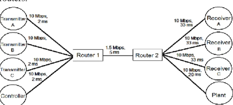
We used two basic benchmark network topologies for analysis: a daisy-chain topology (see Figure 1) and a dumbbell topology (see Figure 6). The daisy-chain topology considered here consists of one sender, one receiver and two routers interconnected by a bottleneck link. The dumbbell topology has several flows competing for bandwidth in a single bottleneck link. Such topologies have been used as benchmark basic test scenarios for network congestion analysis [1, 2, 3, 21, 22, 23]. The bottleneck link can be wireless while the other links can be wired, for example.
The rest of this paper is organized as follows. Section 2 introduces the proposed new ANCE indirect AQM technique. Section 3 presents the network topology for single flow analysis and results. Section 4 details the dumbbell network topology analysis which employs concurrent TCP and NCS flows. Finally, Section 5 concludes the paper.
2.
Acknowledge-Based
Non-Congestion
Estimation (ANCE)
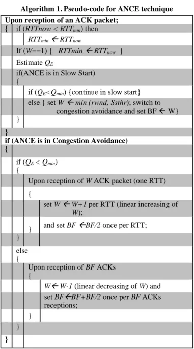
ANCE is a new approach to attain indirect queue management by employing end-to end estimation instead of explicitly using congestion or non-congestion notifications coming from the routers. Accordingly, ANCE is executed at the TCP transmitter and is inspired by ENCN [9]; however, ANCE works with queue length estimation instead of using explicit non-congestion notification. Thus, as it can be observed in the pseudo-code for ANCE, given in Error! Reference source not found., when the estimated queue length (QE) is lower than a threshold Qmin, ANCE interprets that there is no congestion on the path between transmitter and receiver and adjusts its congestion window W. Accordingly, if the TCP transmitter is in Slow Start and QE < Qmin, ANCE calculates its new congestion window as W = min (rwnd; Ssthr), where rwnd is the receiver advertised window and Ssthr is a Slow Start threshold and the TCP transmitter will switch to Congestion Avoidance [24]. In the absence of (estimated) noncongestion, i.e. when QE >= Qmin, Slow Start works as in TCP-Reno protocol [24].
If the TCP sender is in Congestion Avoidance, ANCE employs a fairness mechanism in which the sender will increase its congestion window by one packet size per round trip time (RTT) if and only if a non-congestion is estimated, i.e. if, and only if, QE < Qmin. Otherwise, the transmitter will reduce its window by one packet size upon reception of BF acknowledgement packets (ACKs) in order to maintain the queue length around Qmin. BF (Balance Fairness) is a variable whose dynamics is given in Table 1, which implements a fairness mechanism for ANCE.
Table 1. BF dynamics for fairness in ANCE. Upon W increase BF=BF/2
Upon W decrease BF=BF+BF/2
Therefore, the ANCE sender will reduce its BF variable, with increasing W, and consequently will reduce its congestion window more often than the other ANCE senders with smaller W values. On the other hand, since W does not increase more than once per RTT, i.e. not more than once per reception of W ACK packets, ANCE senders with greater W will increase their congestion windows less often than those with lower W. This fairness mechanism forces each sender to fairly adjust its congestion window. The queue length is estimated according to
), min (RTT now RTT B
QE = − (1)
Algorithm 1. Pseudo-code for ANCE technique
Upon reception of an ACK packet; { if (RTTnow < RTTmin) then
RTTmin RTTnow
If (W==1) { RTTmin RTTnow } Estimate QE
if(ANCE is in Slow Start) {
if (QE<Qmin) {continue in slow start} else { set W min (rwnd, Ssthr); switch to
congestion avoidance and set BF W} }
}
if (ANCE is in Congestion Avoidance) {
if (QE < Qmin) {
Upon reception of W ACK packet (one RTT) {
set W W+1 per RTT (linear increasing of W);
} and set BF BF/2 once per RTT; }
else {
Upon reception of BF ACKs {
W W-1 (linear decreasing of W) and set BFBF+BF/2 once per BF ACKs receptions;
} } }
where RTTnow is the current round-trip time, RTTmin is the minimum RTT observed by the ANCE sender since the beginning of operation. Because the delay between transmitter and receiver could increase by changes on the routing path, if W reaches the minimum value of one segment, the RTTmin is updated to the value of the RTTnow. B is the bandwidth of the bottleneck link [25]. However, since in real applications the bandwidth is not known by the senders, in this paper it is used its end to end estimated value (BE) which is estimated according to
where tamin is the minimal time between arrival of two consecutive ACKs, observed from the beginning of the transmission up to the current time instant and Ackl is the last
received ACK packet length.
3.
Size Daisy-Chain Topology with Single Flow
In order to test the ANCE approach, the benchmark daisy-chain topology illustrated in Figure 1 is employed with a single transmitter-receiver flow on which a transmitter sends packets of 1 kbyte size to a receiver through a network with two routers. Each router can queue up to Q = 17 packets. The initial Ssthr is 30 packets and rwnd = 64 packets. The routers are connected to each other by a link of speed 1.5 Mbps and 5 milliseconds (ms) delay, here called the bottleneck link. The transmitter is connected to router 1 by a link with speed of 10 Mbps and 2 ms latency, while the receiver is connected to router 2 by a link of 10 Mbps speed and 33 ms latency. The network was modeled using timed automata through a language based on TCTL (Timed Computation Tree Logic) implemented in UPPAAL, which is a tool for verification of real-time systems jointly developed by Uppsala University and Aalborg University and supports integer variables, clocks, arrays and user defined functions. UPPAAL is free for academic use [20, 26].
For the UPPAAL simulation, transmitter, receiver, routers, and each channel link were modeled as timed automata, that is, modeled as finite-state machine extended with clock variables and the whole system works as a network of such timed automata in parallel. The detailed implementation in UPPAAL of the network model of Figure 1 is given in [9].
Figure 1. Linear daisy-chain topology used as basic bottleneck configuration
3.1 Simulation Results for Daisy-Chain Topology ANCE, RED, CoDel, PIE and ENCN techniques were modeled in UPPAAL employing TCP-Reno [24]. For RED, CoDel, PIE, and ENCN simulations, it was considered that the ECN bit is available, so the router may set a mark in the IP packet header upon congestion detection.
In these simulations, the following values for RED parameters were used:
, 4 min
Ql
th= 4 ,
. 3 max
Ql
th= Pmax =0.1, W q=0.002, where Ql= 17 kbytes is the buffer size. Details about these RED parameters are given in [1]. For ENCN and ANCE, Qmin = 3 kbytes and initial Ssthr = 16 packets were used. CoDel does not require any parameter setting [2], and PIE employs adaptive parameters [2, 3].
Figure 2 shows the queue dynamics in the bottleneck link for RED, CoDel, PIE, and ENCN, respectively.
Figure 3 and Figure 4 show the growth of TCP-Reno congestion window and the queue dynamics in the bottleneck link for ANCE technique. Furthermore, the throughput for each of these AQM techniques with TCP-Reno implementation is illustrated in Figure 5. The throughput (T) is calculated as specified in [27], i.e. T = NP/Time, where NP is the number of packets transmitted and acknowledged, and Time is the simulation time.
It is clear from Figure 2 that for the simulation scenario investigated here, RED, CoDel, and PIE working with TCP-Reno have several periods where the queue in the bottleneck link remains empty, because these AQM techniques excessively refrain the TCP-Reno transmitter.
Figure 2. Bottleneck queue for RED, CoDel, PIE and ENCN
Figure 3. Sender congestion window for ANCE This bufferempty phenomenon causes performance loss in terms of throughput as shown in Figure 5, whereas ANCE (Figure 4) as well as ENCN [9], avoids bufferempty phenomenon and the router remains busy with queue length oscillating around the chosen Qminvalue, as long as the source has data to send. Thus, compared with the other AQM techniques, ANCE and ENCN presents better throughput. Note from Figure 5 that the throughput curves for ENCN and ANCE are very similar.
Figure 4. Bottleneck queue for ANCE
Figure 5. Thoroughput for RED, CoDel, PIE, ENCN and ANCE
4.
Dumbbell Topology with NCS and Multiple
Concurrent Flows
UDP-like NCS flow share the same network bottleneck with two routers.
Figure 6. Dumbbell topology of three TCP-Reno flows (A, B and C Transmitter- Receiver pairs) and one UDP-like NCS
flow (Controller-Plant pair).
Figure 7 shows a simplified NCS arrangement for the controller and plant interconnected by the network where the plant with transfer function Gp and the remote controller with transfer function Gc are linked through the communication system. A sensor makes measurements of the plant output signal y(k) and transmits it to the controller every h seconds, where h is the sampling period. The controller receives these measurements and uses them as its input signal and thereby calculates the control law u(k), which is sent to the plant through the return communication channel.
Then, the actuator module present in the plant receives this signal u(k) and uses it as its input signal in order to maintain (control) the state of the plant at a certain target value according to a reference, normally given (generated) by the controller module. The communication channel that connects the plant with the controller can incur delays and packet losses. So, 𝜏𝑘𝑠𝑐, 𝜏𝑘𝑐𝑎 and 𝜏𝑘𝑐 represent the time delay between sensor and controller, controller and actuator, and controller processing time, respectively. The switches S1 and S2 model the possibility of packet losses from sensor and controller, respectively. Therefore, with closed switches, packets reach their destinations. Otherwise, they are lost.
Figure 7. NCS representation for controller and plant interconnected by the network in Figure 6
The control systems used here can be found in [28] where a proportional-integral (PI) controller with Kp= 11.86 and Ki= 47.45 is used to control the position of a DC motor (Maxon F2140), i.e. the plant, through the network. The motor transfer function has been identified experimentally and is given by
𝐺𝑝(𝑠) = 36.3
𝑠2+36.17𝑠. (3) In our UPPAAL modeling, each step of the clock corresponds to 1 s. All time events can be solved as multiples of this reference step. UPPAAL has not an ordinary differential equation native solver. However, discretized models that are slow compared to 1µs are properly simulated. So, the discrete equivalent of the plant can be represented with sufficient precision as a finite automata in UPPAAL. The motor transfer function was discretized with sampling period h = 14 ms and
time constant of the employed motor is 27.6 ms, so that it can be represented as a finite automaton in UPPAAL.
Note that only the TCP flows respond to ECN and ENCN notifications, which do not cause any direct effect on the UDP-like NCS flow. In this scenario, in addition to compare the throughput for the TCP flows, the fairness among them was also compared employing the fairness index of [29].
Moreover, in order to weigh up the performance in NCS, the Integral Time Absolute Error (ITAE) was used. Accordingly, the best control system is the one with lowest ITAE value. Transmitters and receivers were modeled according to [9]. Next subsections present the plant and controller UPPAAL modeling.
4.1 Plant UPPAAL Model
Figure 8 illustrates the UPPAAL plant simulation model which consists of two locations called SamplingP and
SendingP. The automaton starts at SamplingP location. The
pseudo-code for this automaton is given in Algorithm 2. Table 2 describes all variables, functions and constants used in this UPPAAL model.
Figure 8. UPPAAL automaton model for the plant Algorithm 2. Pseudo-code for Plant Automaton
Start in SamplingP location;
{ if (tp >=h) { then
Go to SendingP location, reset tp and call ComputePosition and ComputeITA functions; In SendingP location wait for Tpsm time units, then return to SamplingP location and call
SendMeasured function. }
else {
wait until tp >= h becomes true; }
}
Table 2. Variable, function and constant descriptions for the plant automaton model
Name Descriptions
h Sampling period (14 ms). tp Clock used in plant automaton. Tpsm
Constant time threshold equal to the time required to put a packet of 48 bytes in a 10 Mbps channel.
ComputePosition
Function called every h time units It computes the plant output signal y(k).
ComputeITAE Function called every h time units. It
computes the ITAE value.
SendMesasured
4.2 Controller UPPAAL Model
Figure 9 illustrates the UPPAAL controller model which consists of two locations called SamplingCS and SendingCS. The automaton starts at SamplingCS location. The pseudo-code for this automaton is given in Algorithm 3
,
Table 3 describes the variables, functions and constants used in this UPPAAL model.Figure 9. UPPAAL automaton model for the controller Algorithm 3. Pseudo-code for Controller Automaton Start inSamplingCSlocation;
{ if (tc >=h) { then
Go to SendingCS location, reset tc and call the functions ComputeControlSignal; In SendingCS location wait for Tcsctime units, then return to SamplingCS location and call SendControlSignal function.
} else {
wait until tc >=h becomes true; }
}
Table 3. Variable, function and constant descriptions for the controller automaton model
Name Descriptions
tc Clock used in controller automaton.
Tcsc
Constant time threshold equal to the time required to put a packet of 48 bytes in a 10 Mbps channel.
ComputeControlSignal
Function called every h time units
It computes the controller output signal u(k).
SendControlSignal
Function called when the controller sends a packet with u(k) It updates the number of packets in the channel located between the router 2 and the controller
4.3 Controller Simulation Results for Dumbbell
Topology
All simulation were run for 30 seconds Figure 10 to Figure 15 presents the TCP throughput for each of the three flows (A, B and C) for DT, Red, CoDel, PIE, ENCN and ANCE, respectively. The total throughput, i.e. the aggregate TCP throughput of flows A, B and C, as a function of simulation time for DT, RED, CoDel, PIE, ENCN and ANCE is presented in Figure 16. As it can be observed, besides requiring fewer resources for implementation, ANCE
provides a throughput close to ENCN and CoDel overcoming RED and PIE techniques.
Figure 10. Throughput for DT
Figure 11. Throughput for RED
Figure 12. Throughput for CoDel
Figure 13. Throughput for PIE
Figure 14. Throughput for ENCN
Figure 15: Throughput for ANCE
Furthermore, the fairness mechanism used in ANCE makes each flow to converge essentially to the same throughput. Thus, ANCE outperforms DT, RED, CoDel and PIE in terms of fairness for TCP flows getting better Jain fairness index than those other AQM techniques (see Figure 17).
On the other hand, for the UDP-like flow for controller and plant, Figure 18 to Figure 23 shows the motor position following a square wave reference (R) between 1 and 2 radians, with period 2 seconds for all considered methods. Figure 24 to Figure 29shows the corresponding queue length dynamics.
Figure 17. Index of Jain for fairness comparison of TCP throughput
As it can be observed in Figure 29, ANCE also avoids bufferbloat problems; consequently as depicted in Figure 30, ANCE provides better performance than DT, RED, CoDel, and PIE for the UDP-like NCS flows in terms of ITAE, resulting in an ITAE behavior very close to the obtained with ENCN. Notice that the ITAE depicted in Figure 30 is the result of one simulation. But deterministic and random events occur on the Internet, consequently one simulation captures only one of the several possibilities. Then, we use the UPPAAL SMC (Statistical Model Checking) to compare the performance of different AQM techniques in terms of ITAE for NCS. Accordingly, we calculate the probability of exceeding a certain value of ITAE when different AQM techniques are implemented in the routers.
Table 4 presents the estimated probability interval for ITAE being greater than 8727 radians_seconds (rad.s) until 30 seconds with 95% confidence for DT, RED, CoDel, PI, ENCN, and ANCE. As it can be observed, ENCN and ANCE has the lowest probability interval.
Figure 18. Motor position for DT
Figure 19. Motor position for RED
Figure 20. Motor position for CoDel
Figure 21. Motor position for PIE
Figure 22. Motor position for ENCN
Figure 23. Motor position for ANCE
Figure 24. Queue length for DT
Figure 25. Queue length for RED
Figure 26. Queue length for CoDel
Figure 27. Queue length for PIE
Figure 28. Queue length for ENCN
Figure 30. ITAE for UDP-like NCS flow for each AQM technique
Table 4. Probability intervals for ITAE being greater than 8727 rad.s until 30 seconds
AQM Technique Probability Intervals
DT 0.902 to 1
RED 0.649 to 0.749
CoDel 0.457 to 0.557
PIE 0.068 to 0.168
ENCN and ANCE 0 to 0.097
Figure 31 illustrates the Cumulative Probability Distribution for the ITAE being greater than 8727 rad.s in up to 30 seconds for RED, CoDel, and PIE. Note that there are no curves for ENCN and ANCE because when these AQM techniques were implemented in the routers the ITAE does not overcome 8727 rad.s until 30 seconds under any possible situation. On the other hand, RED and DT are most likely to exceed this value, which is a consequence of the bufferbloat phenomenon.
Figure 31. Cumulative Probability Distribution for ITAE being greater than 8727 rad.s
4.4 ANCE versus other TCP Protocols
In addition to comparisons with AQM techniques, we also compared the ANCE performance with other TCP ECN-based protocols, i.e. protocols that match AQM techniques implemented in routers with updates in the TCP window through the ECN bit [6, 7, 8]. Figure 32 and Figure 33 illustrate the total TCP throughput and the ITAE for the NCS as a function of simulation time for TCP-Jersey, E-DCTCP and ANCE, respectively. EDCTCP outperforms ANCE in total throughput for TCP flows, but in compensation ANCE provides better ITAE for the NCS UDP-like flow. It happens because EDCTCP presents more bufferbloat phenomena than ANCE, as it can be observed in Figure 29 and Figure 34.
Figure 32. Throughput for TCP-Jersey, E-DCTCP and ANCE
On the other hand, TCP-Jersey presents poor performance in terms of throughput for TCP flows, but the best ITAE for the NCS UDP-like flow. It happens because TCP-Jersey presents more bufferempty phenomena than E-DCTCP and ANCE, as it can be observed in Figure 35, Figure 34 and Figure 29.
Figure 33. ITAE for TCP-Jersey, E-DCTCP and ANCE Note that unlike TCP-Jersey and E-DCTCP, ANCE does not require the ECN bit, and despite of using fewer resources, it achieves practically the same and even better performance than those protocols.
Figure 34. Queue Length for E-DCTCP
Figure 35. Queue Length for TCP-Jersey
5.
Conclusions
This work presents a new queue management methodology which consists of an end-to-end indirect queue control through queue length estimation employed by TCP transmitters instead of using explicit congestion or non congestion notifications from routers. Accordingly, a new queue management called Acknowledge-based Non-Congestion Estimation (ANCE) was developed, which, unlike ECN schemes, instead of notifying congestion in the router, it estimates non-congestion on the path. The ANCE algorithm was compared with DT, RED, CoDel, PIE and ENCN AQM techniques in a basic daisy-chain scenario and TCP-Jersey and E-DCTCP in a dumbbell network topology in which three generic TCP flows share the same network bottleneck with two routers using UDP-like NCS flow. In this scenario, ANCE presented close throughput performance to ENCN overcoming RED, PIE and TCP-Jersey, as well as better fairness in terms of Jain’s fairness index for the generic TCP flows and better ITAE performance for the UDP-like NCS flow than DT, RED, CoDel, PIE, and E-DCTCP.
communication, as well as UDP networked control systems (NCS) jointly simulated with other TCP flows, and reveals influences of Internet traffic features in NCS through simulations and statistical verification. In the context of Internet of Things, the sharing of networks has growing relevance and future network protocols may take care of communication along with NCS data. Future work can extend the analysis to other traffic conditions and scenarios (such as more complex dumbbell topologies).
6.
Acknowledgement
This work was supported by Fundação de Amparo à Ciência e Tecnologia de Pernambuco (FACEPE), by Coordenação de Aperfeiçoamento de Pessoal de Nível Superior (CAPES) and by Conselho Nacional de Desenvolvimento Científico e Tecnológico (CNPq), Brazil.
References
[1] S. Floyd and V. Jacobson, “Random early detection gateways for congestion avoidance,” IEEE/ACM Trans. Networking, Vol. 1, No. 4, pp. 397-413, 1993.
[2] K. Nichols and V. Jacobson, “Controlling queue delay: a modern AQM is just one piece of the solution to bufferbloat,” ACM Queue - Networks, Vol. 10, No. 5, pp. 1-15, 2012.
[3] R. Pan, P. Natarajan, C. Piglione, M. S. Prabhu, V. Subramanian, F. Baker, and B. VerSteeg, “PIE: A lightweight control scheme to address the bufferbloat problem,” IEEE International Conference on High Performance Switching and Routing (HPSR), Taipei-Taiwan, pp. 148-15, 2013.
[4] Y. Narasimha Reddy, P. V. S. Srinivas, “A Routing Delay Predication Based on Packet Loss and Explicit Delay Acknowledgement for Congestion Control in MANET,” International Journal of Communication Networks and Information Security (IJCNIS), Vol 10, No 3, pp. 447-453, 2018.
[5] S. Floyd, “TCP and explicit congestion notification,” ACM Computer Communications Review, Vol. 24, No. 5, pp. 8–23, 1994.
[6] K. Xu, Y. Tian, and N. Ansari, “TCP-Jersey for wireless IP communications,” IEEE Journal on selected areas in comunications, Vol. 22, No. 4, pp. 747-756, 2004.
[7] M. Alizadeh, A. Greenberg, D. A. Maltz, J. Padhye, P. Patel, B. Prabhakar, S. Sengupta, and M. Sridharan, “Data center TCP DCTCP,” in Proc. of ACM SIGCOMM International Conference, New York, NY, USA, pp. 63-74, 2010.
[8] Y. Huang and B. Hu, “Enhanced DCTCP to explicitly inform of packet loss,” IEEE International Conference on Communications (ICC), London,UK, pp. 5511-5516, 2015.
[9] L. M. A. Sup, R. M. de Moraes, and A. Bauchspiess, “Simultaneous TCP and NCS flows in a UPPAAL framework with a new AQM technique,” IEEE International Conference on Industrial Informatics (INDIN), Poitiers, France, pp. 80-85, 2016.
[10] K. J. Åström and B. Wittenmark, “Computer-Controlled Systems: Theory and Design, 3rd ed. Englewood Cliffs, NJ: Prentice-Hall, 1997. [11] W. Zhang, M. S. Brannicky, and S. M. Philips, “Stability of networked control systems,” IEEE Control Systems Magazine, Vol. 21, No. 1, pp. 84–99, 2001.
[12] Z. Taferra, “Process control over wireless sensor networks,” Master’s thesis, Kungliga Tekniska Högskolan (KTH), Stockholm, Sweden, 2013.
[13] F. Janabi-Sharifi and I. Hassanzadeh, “Experimental analysis of mobile-robot teleoperation via shared impedance control,” IEEE Trans. on Systems, Man, and Cybernetics, Part B (Cybernetics), Vol. 41, No. 2, pp. 591-606, 2011.
[14] X. Ge, F. Yang, and Q.-L. Han, “Distributed networked control systems: A brief overview,” Information Sciences, Vol. 380, No. 1, pp. 117-131, 2017.
[15] J. M. Llopis, J. Pieczerak, and T. Janaszka, “Minimizing latency of critical traffic through SDN,” IEEE International Conference on Networking, Architecture, and Storage (NAS), Long Beach, CA, USA, pp 1-6 2016.
[16] H. Lin, S. Hongye, and S. Zhan, “Optimal estimation in UDP-Like networked control systems with intermittent inputs: Stability analysis
and suboptimal filter design,” IEEE Trans. on Automatic Control, Vol. 61, No. 7, pp. 1794-1809, 2016.
[17] T. Samad, “Control systems and the internet of things,” IEEE Control Systems Magazine, Vol. 36, No. 1, pp. 13-16, 2016.
[18] Ali M. A. Abuagoub, “IoT Security Evolution: Challenges and Countermeasures Review,” International Journal of Communication Networks and Information Security (IJCNIS), Vol 11, No 3, pp. 342-351, 2019.
[19] K. Ramakrishnan, S. Floyd, and D. Black, “The Addition of Explicit Congestion Notification (ECN) to IP,” RFC 3168, pp. 1-63, September 2001.
[20] H. B. Mokadem, B. Bérard, O. D. Smet, and J.-M. Roussel, “Verification of a timed multitask system with uppaal.” IEEE Trans. on Automation Science and Engineering, Vol. 7, No. 4, pp. 921–932, 2010. [21] F. Jäger, T. C. Schmidt, and M. Wählisch, “How dia-shows turn Into video flows: adapting scalable video communication to heterogeneous network conditions in real-time,” IEEE Conference on Local Computer Networks (LCN), Edmonton, Canada, pp. 218-226, 2014.
[22] C. Parsa and J. Garcia-Luna-Aceves, “Improving TCP congestion control over internets with heterogeneous transmission media,” IEEE International Conference on Network Protocols (ICNP), Toronto, Canada, pp. 213-221, 1999.
[23] N. Kuhn, P. Natarajan, N. khademi, D. Ros et al., “Characterization guidelines for active queue management (AQM),” RFC 7928, pp. 1-37, July 2016.
[24] V. Jacobson, “Modified TCP congestion avoidance algorithm,” Technical Report 30, 1990.
[25] P. Sreekumari and S.-H. Chung, “TCP NCE: A unified solution for noncongestion events to improve the performance of tcp over wireless networks,” EURASIP Journal on Wireless Communications and Networking, Vol. 2011, No. 1, pp. 1–20, 2011.
[26] G. Behrmann, A. David, K. G. Larsen, J. Hakansson, P. Pettersson, W. Yi, and M. Hendriks, “UPPAAL 4.0,” QEST, Riverside, CA, USA, pp. 1-48, 2006.
[27] R. Oliveira and T. Braun, “A smart TCP acknowledgment approach for multihop wireless networks,” IEEE Trans. on Mobile Computing, Vol. 6, No. 2, pp. 192–205, 2007.
[28] L. F. d. C. Figueredo, E. D. S. Alves, J. Y. Ishihara, G. A. Borges, and A. Bauchspiess, “Stability of networked control systems with
dynamic controllers in the feedback loop,” IEEE Mediterranean Conference on Control and Automation (MED), Marrakech, Morocco, pp. 99-104, 2010.