Dell PowerEdge RAID Controller (PERC) H310, H710,
H710P, and H810
Notes, Cautions, and Warnings
NOTE: A NOTE indicates important information that helps you make better use of your computer.
CAUTION: A CAUTION indicates either potential damage to hardware or loss of data and tells you how to avoid the problem.
WARNING: A WARNING indicates a potential for property damage, personal injury, or death.
© 2013 Dell Inc. All Rights Reserved.
Trademarks used in this text: Dell™, the Dell logo, Dell Boomi™, Dell Precision™ , OptiPlex™, Latitude™, PowerEdge™, PowerVault™,
PowerConnect™, OpenManage™, EqualLogic™, Compellent™, KACE™, FlexAddress™, Force10™, Venue™ and Vostro™ are trademarks
of Dell Inc. Intel®, Pentium®, Xeon®, Core® and Celeron® are registered trademarks of Intel Corporation in the U.S. and other countries.
AMD® is a registered trademark and AMD Opteron™, AMD Phenom™ and AMD Sempron™ are trademarks of Advanced Micro
Devices, Inc. Microsoft®, Windows®, Windows Server®, Internet Explorer®, MS-DOS®, Windows Vista® and Active Directory® are
either trademarks or registered trademarks of Microsoft Corporation in the United States and/or other countries. Red Hat® and
Red Hat® Enterprise Linux® are registered trademarks of Red Hat, Inc. in the United States and/or other countries. Novell® and SUSE®
are registered trademarks of Novell Inc. in the United States and other countries. Oracle® is a registered trademark of Oracle
Corporation and/or its affiliates. Citrix®, Xen®, XenServer® and XenMotion® are either registered trademarks or trademarks of Citrix
Systems, Inc. in the United States and/or other countries. VMware®, vMotion®, vCenter®, vCenter SRM™ and vSphere® are registered
trademarks or trademarks of VMware, Inc. in the United States or other countries. IBM® is a registered trademark of International
Business Machines Corporation. 2013 - 03
Contents
1 Overview...9
Supported Operating Systems
...10
Getting Help
... 10
Contacting Dell
...11
Related Documentation
...11
Documentation Feedback
... 11
2 Features... 13
Physical Disk Power Management
...13
Configured Spin Down Delay
... 13
Types Of Virtual Disk Initialization
... 14
Background Initialization Of Virtual Disks
...14
Full Initialization Of Virtual Disks
...14
Fast Initialization Of Virtual Disks
...14
Consistency Checks
...14
Disk Roaming
... 15
Using Disk Roaming
...15
FastPath
... 15
Configuring FastPath-Capable Virtual Disks
... 15
Virtual Disk Migration
... 16
Migrating Virtual Disks
...16
Virtual Disk Write Cache Policies
...17
Write-Back And Write-Through
...17
Conditions Under Which Write-Back Is Employed
... 17
Conditions Under Which Forced Write-Back With No Battery Is Employed
... 17
Virtual Disk Read Cache Policies
...18
Reconfiguration Of Virtual Disks
...18
Fault Tolerance
...20
The SMART Feature
...20
Automatic Replace Member With Predicted Failure
... 20
Patrol Read
... 21
Redundant Path Support (For PERC H810 Only)
...21
Physical Disk Failure Detection
...22
Using Persistent Hot Spare Slots
...22
Physical Disk Hot Swapping
...22
Using Replace Member And Revertible Hot Spares
...22
Recovering Cache Data
... 23
Battery Transparent Learn Cycle
...23
TLC Time Frame
...23
Conditions For Replacing The Battery
...23
3 Deploying The PERC Card...25
Removing The PERC Controller
...25
Installing The PERC Controller
...27
Support For Internal Multiple Controllers
...28
Setting Up Redundant Path Support On The PERC H810 Adapter
...28
Reverting To Single Path Support From Redundant Path Support For PERC H810
...28
4 Driver Installation...31
Pre-Installation Requirements For Windows Driver Installation
...31
Creating The Device Driver Media For Windows Driver Installation
... 31
Downloading Drivers From The Dell Systems Service And Diagnostic Tools Media For Windows
...31
Downloading Drivers From The Dell Support Website For Windows
... 32
Installing Driver During a Windows Server 2008/2008 R2 Installation
... 32
Installing Windows Server 2008/2008 R2 For A New RAID Controller
... 32
Updating Existing Windows Server 2008 Or Windows Server 2008 R2
...33
Updating The Linux Driver
... 33
Installing Or Updating The RPM Driver Package With DKMS Support
... 34
Installing Or Updating The RPM Driver Package With KMOD Support
... 34
Installing Or Updating The RPM Driver Package With KMP Support
...34
5 Management Applications For PERC Cards... 37
Dell OpenManage Storage Management
...37
BIOS Configuration Utility
...37
Entering The BIOS Configuration Utility
... 37
Exiting The Configuration Utility
... 38
Menu Navigation Controls
... 38
Setting Up Virtual Disks
...39
Virtual Disk Management
... 41
Creating Virtual Disks
...41
Selecting Virtual Disk Parameters
... 42
Converting Physical Disk To RAID Capable For PERC H310
...42
Converting Physical Disk To Non-RAID For PERC H310
...43
Initializing Virtual Disks
... 43
Checking Data Consistency
... 43
Running A Data Consistency Check
...43
Importing Or Clearing Foreign Configurations Using The VD Mgmt Menu
...44
Break Mirror
...46
Managing Preserved Cache
...46
Managing Dedicated Hot Spares
...47
Deleting Virtual Disks
... 48
Deleting Disk Groups
...48
Clearing The Configuration
...48
BIOS Configuration Utility Menu Options
... 49
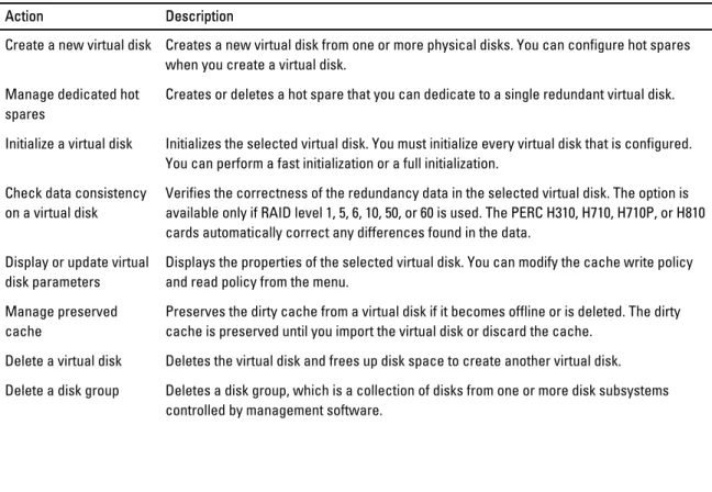
Virtual Disk Management (VD Mgmt)
...49
Virtual Disk Actions
...51
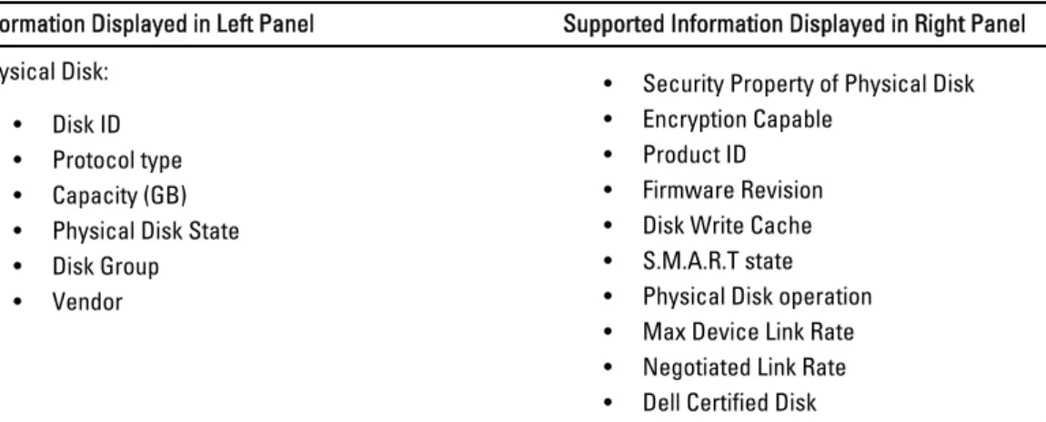
Physical Disk Management (PD Mgmt)
... 52
Physical Disk Actions
...52
Rebuild
...53
Controller Management (Ctrl Mgmt)
... 53
Controller Management Actions
...53
Foreign Configuration View
...54
Physical Disk Management
... 54
Setting LED Blinking
... 54
Creating Global Hot Spares
...55
Removing Global Or Dedicated Hot Spares
... 55
Replacing An Online Physical Disk
... 55
Restrictions and Limitations
...56
Stopping Background Initialization
... 56
Performing A Manual Rebuild Of An Individual Physical Disk
...56
Controller Management
...57
Enabling Boot Support
...57
Enabling Boot Support For A BIOS-Enabled Controller
...57
Enabling BIOS Stop On Error
...57
Enabling Auto Import
...57
Disabling Auto Import
...58
Restoring Factory Default Settings
... 58
UEFI RAID Configuration Utility
...58
Entering The UEFI RAID Configuration Utility
...58
Exiting The UEFI RAID Configuration Utility
...59
Configuration Options
...59
Controller Management Menu
...59
Virtual Disk Management
...60
Physical Disk Management Menu
... 60
Enclosure Management
...60
6 CacheCade... 61
CacheCade Virtual Disk Management
... 62
Creating CacheCade Virtual Disks
... 62
Deleting CacheCade Virtual Disks
... 63
Reconfiguring CacheCade Virtual Disks
... 63
Automatic Reconfiguration Of CacheCade Virtual Disks
...63
Manual Resizing Of CacheCade Virtual Disks
...63
7 Security Key And RAID Management...65
Security Key Implementation
...65
Security Key Management In The BIOS Configuration Utility
... 65
Local Key Management (LKM)
...65
Creating A Security Key
... 66
Changing The Security Key
... 66
Deleting A Security Key
... 67
Creating Secured Virtual Disks
... 67
Securing Pre-Existing Virtual Disks
... 67
Securing Pre-Existing Virtual Disks
... 68
Importing Or Clearing Secured Foreign Configurations And Secure Disk Migration
... 68
Instant Secure Erase
...69
Troubleshooting Security Key Errors
...69
Secured Foreign Import Errors
...69
Failure to Select Or Configure Non Self-Encrypting Disks (Non-SED)
...69
Failure To Delete Security Key
...70
Failure To Instant Secure Erase Task On Physical Disks
...70
8 Troubleshooting...71
BIOS Error Messages
... 71
Discovery Error Message
...71
Extra Enclosure Error Message
... 71
Cache Data Lost Error Message
... 71
Missing Disks In Virtual Disk Error Message
...72
Previous Configuration Of Disks Removed Error Message
...72
Missing Virtual Disks Error Message
...72
Dirty Cache Data Error Message
... 73
BIOS Disabled Error Message
... 73
Drive Configuration Changes Error Message
... 73
Adapter At Baseport Not Responding Error Message
...74
Offline Or Missing Virtual Drives With Preserved Cache Error Message
...74
Virtual Disks Offline Error Message
...74
Virtual Disks Degraded Error Message
...74
Virtual Disks Partially Degraded Error Message
... 75
Firmware Fault State Error Message
... 75
Foreign Configuration Found Error Message
... 75
Foreign Configuration Not Found In <Ctrl> <R> Error Message
... 76
Previous Configuration Cleared Or Missing Error Message
...76
Invalid SAS Topology Detected Error Message
...76
Multibit ECC Errors Detected Error Messages
...76
Configured Disks Removed Or Not Accessible Error Message
...77
Battery Discharged Or Disconnected Error Message
... 77
Degraded State Of Virtual Disks
... 77
Memory Errors
...78
Preserved Cache State
...78
General Issues
...78
PERC Card Has Yellow Bang In Device Manager
... 78
PERC Card Not Seen In Device Manager
... 78
No Hard Drives Found Error Message During Microsoft Windows Server 2003 Installation
...78
Physical Disk Issues
... 79
Physical Disk In Failed State
... 79
Unable to Rebuild A Fault Tolerant Virtual Disk
... 79
Fatal Error Or Data Corruption Reported
...79
Physical Disk Displayed As Blocked
...79
Multiple Disks Become Inaccessible
...80
Rebuilding A Failed Physical Disk
... 80
Virtual Disk Fails During Rebuild Using A Global Hot Spare
... 80
Virtual Disk Fails During Rebuild Using A Dedicated Hot Spare
...80
Physical Disk Fails During Reconstruction On Redundant Virtual Disk
... 81
Virtual Disk Fails Rebuild Using A Dedicated Hot Spare
...81
Physical Disk Takes A Long Time To Rebuild
...81
SMART Errors
... 81
Smart Error Detected On A Physical Disk In A Redundant Virtual Disk
...81
Smart Error Detected On A Physical Disk In A Non-Redundant Virtual Disk
...82
Replace Member Errors
...82
Source Disk Fails During Replace Member Operation
... 82
Target Disk Fails
...82
General Disk Fails
...82
Linux Operating System Errors
... 82
Virtual Disk Policy Is Assumed As Write-Through Error Message
...82
Driver Does Not Auto-Build Into New Kernel
... 83
Unable To Register SCSI Device Error Message
...83
Disk Carrier LED Indicators
...84
RAID Terminology
...85
Disk Striping
... 85
Disk Mirroring
...86
Spanned RAID Levels
...86
1
Overview
The Dell PowerEdge RAID Controller (PERC) H310, H710, H710P, and H810 family of storage controller cards has the following characteristics:
• Complies with serial-attached SCSI (SAS) 2.0 providing up to 6 Gb/sec throughput.
• Supports Dell-qualified serial-attached SCSI (SAS) hard drives, SATA hard drives, and solid-state drives (SSDs). NOTE: Mixing SAS and SATA drives within a virtual disk is not supported. Also, mixing hard drives and SSDs within a virtual disk is not supported.
NOTE: Mixing disks of different speeds (7,200 rpm, 10,000 rpm, or 15,000 rpm) and bandwidth (3 Gbps or 6 Gbps) PCIe while maintaining the same drive type (SAS or SATA) and technology (HDD or SSD) is supported.
• Offers RAID control capabilities which include support for RAID levels 0, 1, 5, 6, 10, 50, and 60.
NOTE: PERC H310 supports RAID 5 with limited performance and does not support RAID 6 and RAID 60. • Provides reliability, high performance, and fault-tolerant disk subsystem management.
• Offers Non-RAID support for direct access to disk drives (PERC H310 only).
NOTE: Operating systems can directly access Non-RAID hard drives. A Non-RAID hard drive is not fault-tolerant and cannot be recovered if it fails. Only the PERC H310 controller allows configuration of disk drives as Non-RAID.
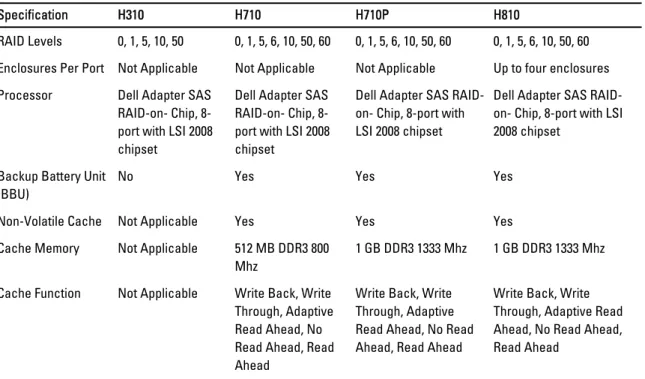
The following table compares the hardware configurations for the PERC H310, H710, H710P, and H810 cards. Table 1. PERC H310, H710, H710P, and H810 Cards Hardware Configurations
Specification H310 H710 H710P H810
RAID Levels 0, 1, 5, 10, 50 0, 1, 5, 6, 10, 50, 60 0, 1, 5, 6, 10, 50, 60 0, 1, 5, 6, 10, 50, 60 Enclosures Per Port Not Applicable Not Applicable Not Applicable Up to four enclosures Processor Dell Adapter SAS
RAID-on- Chip, 8-port with LSI 2008 chipset
Dell Adapter SAS RAID-on- Chip, 8-port with LSI 2008 chipset
Dell Adapter SAS RAID-on- Chip, 8-port with LSI 2008 chipset
Dell Adapter SAS RAID-on- Chip, 8-port with LSI 2008 chipset
Backup Battery Unit (BBU)
No Yes Yes Yes
Non-Volatile Cache Not Applicable Yes Yes Yes Cache Memory Not Applicable 512 MB DDR3 800
Mhz
1 GB DDR3 1333 Mhz 1 GB DDR3 1333 Mhz Cache Function Not Applicable Write Back, Write
Through, Adaptive Read Ahead, No Read Ahead, Read
Write Back, Write Through, Adaptive Read Ahead, No Read Ahead, Read Ahead
Write Back, Write Through, Adaptive Read Ahead, No Read Ahead, Read Ahead
Specification H310 H710 H710P H810 Maximum number of
spans per Disk Group
8 8 8 8
Maximum number of Virtual Disks per Disk Group
16 16 16 16
Online Capacity Expansion
Yes Yes Yes Yes
Dedicated and Global Hot Spares
Yes Yes Yes Yes
Hot Swap Devices Supported
Yes Yes Yes Yes
Hardware XOR Engine
Yes Yes Yes Yes
Redundant Path Support
Yes Yes Yes Yes
Supported Operating Systems
The PERC H310, H710, and H710P cards support the following operating systems: • Microsoft Windows Server 2012
• Microsoft Windows Server 2008 including Hyper-V virtualization • Microsoft Windows Server 2008 R2 and later
• Red Hat Enterprise Linux version 5.8 and later (32-bit and 64-bit) • Red Hat Enterprise Linux version 6.2 and later (64-bit)
• SUSE Linux Enterprise Server version 10 SP4 (64-bit) • SUSE Linux Enterprise Server version 11 SP2 (64-bit) • VMware ESX 4.1 and ESXi 4.1 Update 2 and later • VMware ESXi 5.0 and later
NOTE: For the latest list of supported operating systems and driver installation instructions, see the system documentation at dell.com/support/manuals. For specific operating system service pack requirements, see the Drivers and Downloads section at dell.com/support/manuals.
Contacting Dell
NOTE: Dell provides several online and telephone-based support and service options. If you do not have an active Internet connection, you can find contact information on your purchase invoice, packing slip, bill, or Dell product catalog. Availability varies by country and product, and some services may not be available in your area. To contact Dell for sales, technical support, or customer-service issues:
1. Go to dell.com/contactdell.
2. Select your country or region from the interactive world map.
When you select a region, the countries for the selected regions are displayed. 3. Select the appropriate language under the country of your choice.
4. Select your business segment.
The main support page for the selected business segment is displayed. 5. Select the appropriate option depending on your requirement.
Related Documentation
NOTE: For all storage controllers and PCIe SSD documents, go to dell.com/support/manuals, then, Choose from a list of all Dell products → Servers, Storage & Networking → Dell Adapters .
NOTE: For all Dell OpenManage documents, see dell.com/support/manuals, then, Choose from a list of all Dell products → Software, Electronics & Peripherals → Software → Enterprise System Management .
NOTE: For all operating system documents, go to dell.com/support/manuals, then, Choose from a list of all Dell products → Software, Electronics & Peripherals → Software → Operating System .
NOTE: For all PowerEdge and PowerVault documentation, go to dell.com/support/manuals and enter the system service tag to get your system documentation.
• Dell PowerEdge RAID Controller (PERC) H310, H710, H710P, and H810 User's Guide—Discusses features, installation, management and troubleshooting of PERC cards.
• Product-specific Dell PowerVault Owner's Manual—Discusses features, repair, management of PowerVault system.
• Product-specific Dell PowerEdge Owner's Manual—Discusses features, repair, management of PowerEdge system.
Documentation Feedback
If you have feedback for this document, write to [email protected]. Alternatively, you can click on the Feedback link in any of the Dell documentation pages, fill up the form, and click Submit to send your feedback.
2
Features
Some of the features discussed for PowerEdge RAID Controller (PERC) H310, H710, H710P, and H810 cards are: • Physical Disk Power Management
• Types of Virtual Disk Initialization • Consistency Checks
• Disk Roaming • Fast Path
• Virtual Disk Migration
• Reconfiguration Of Virtual Disks • Fault Tolerance
• Patrol Read
Physical Disk Power Management
Physical disk power management is a power saving feature of the PERC H310, H710, H710P, and H810 cards. The feature allows disks to be spun down based on disk configuration and I/O activity. The feature is supported on all rotating SAS and SATA disks and includes unconfigured, configured and hot-spare disks. The physical disk power management feature is disabled by default. The feature can be enabled in the Dell Open Manage Storage Management application using the Unified Extensible Firmware Interface (UEFI) RAID Configuration utility. For more information, see the Dell OpenManage documentation at dell.com/support/manuals.
There are four power saving modes available: No Power
Savings (default mode)
All power savings features are disabled.
Balanced Power Savings
Spin down is enabled only for unconfigured and hot spare disks. Maximum Power
Savings
Spin down is enabled for configured, unconfigured and hot spare disks. Customized
Power Savings
All power savings features are customizable. You can specify a Quality of Service window during which the configured disks are excluded from spin-down.
Configured Spin Down Delay
NOTE: The Configured Spin Down Delay option is not applicable for the No Power Savings mode.
The amount of time to wait before spinning down disks can be set using Configured Spin Down Delay. The minimum value of the timer is 30 minutes (default) and the maximum is one day. Disks are spun down automatically and spun up when accessed. All disks are spun up on reboot.
NOTE: There is a delay to I/O operations when a configured disk is being spun up.
Types Of Virtual Disk Initialization
You can initialize the virtual disks as described in the following sections:
CAUTION: The initializing virtual disks task erases the files and file systems while keeping the virtual disk configuration intact. Initializing a virtual disk destroys all data on the virtual disk.
NOTE: The initialization operations mentioned here are not applicable for Non-RAID disks.
Background Initialization Of Virtual Disks
Background Initialization (BGI) is an automated process that writes the parity or mirror data on newly created virtual disks. BGI does not run on RAID 0 virtual disks. You can control the BGI rate in the Dell OpenManage storage management application. Any change in the BGI rate does not take effect until the next BGI run.
NOTE: You cannot disable BGI permanently. If you cancel BGI, it automatically restarts within five minutes. For information on stopping BGI, see the topic Stopping Background Initialization.
NOTE: Unlike full or fast initialization of virtual disks, background initialization does not clear data from the physical disks.
NOTE: CC/BGI typically causes some loss in performance until the operation completes.
Consistency Check (CC) and BGI perform similar functions in that they both correct parity errors. However, CC reports data inconsistencies through an event notification, but BGI does not. You can start CC manually, but not BGI.
Full Initialization Of Virtual Disks
Performing a full initialization on a virtual disk overwrites all blocks and destroys any data that previously existed on the virtual disk. Full initialization of a virtual disk eliminates the need for the virtual disk to undergo a BGI. Full initialization can be performed after the creation of a virtual disk.
During full initialization, the host is not able to access the virtual disk. You can start a full initialization on a virtual disk by using the Slow Initialize option in the Dell OpenManage storage management application. For more information on using the BIOS Configuration Utility to perform a full initialization, see the topic Initializing Virtual Disks.
NOTE: If the system reboots during a full initialization, the operation aborts and a BGI begins on the virtual disk.
Fast Initialization Of Virtual Disks
A fast initialization on a virtual disk overwrites the first and last 8 MB of the virtual disk, clearing any boot records or partition information. The operation takes only 2–3 seconds to complete and is recommended when you are recreating virtual disks. To perform a fast initialization using the BIOS Configuration Utility, see the topic Initializing Virtual Disks
Consistency Checks
Consistency Check (CC) is a background operation that verifies and corrects the mirror or parity data for fault tolerant virtual disks. It is recommended that you periodically run a consistency check on virtual disks.
You can manually start a CC using the BIOS Configuration Utility or the Dell OpenManage storage management application. You can schedule CC to run on virtual disks using a Dell OpenManage storage management application. To start a CC using the BIOS Configuration Utility, see the topic Checking Data Consistency.
Disk Roaming
Disk roaming is moving the physical disks from one cable connection or backplane slot to another on the same controller. The controller automatically recognizes the relocated physical disks and logically places them in the virtual disks that are part of the disk group. You can perform disk roaming only when the system is turned off.
CAUTION: Do not attempt disk roaming during RAID level migration (RLM) or online capacity expansion (OCE). This causes loss of the virtual disk.
Using Disk Roaming
Perform the following steps to use disk roaming:
1. Turn off the power to the system, physical disks, enclosures, and system components. 2. Disconnect power cables from the system.
3. Move the physical disks to desired positions on the backplane or the enclosure. 4. Perform a safety check. Make sure the physical disks are inserted properly. 5. Turn on the system.
The controller detects the RAID configuration from the configuration data on the physical disks.
FastPath
FastPath is a feature that improves application performance by delivering high I/O per second (IOPs). The Dell PowerEdge RAID Controller (PERC) H710P and H810 cards support FastPath.
FastPath is a further enhancement of the Cut Through IO (CTIO) feature, introduced in PERC H700 and PERC H800, to accelerate IO performance by reducing the IO processing overhead of the firmware. CTIO reduces the instruction count required to process a given IO. It also ensures that the optimal IO code path is placed close to the processor to allow faster access when processing the IO.
Under specific conditions with FastPath, the IO by-passes the controller cache and is committed directly to the physical disk from the host memory, through the second core of the dual-core RAID-on-Chip (ROC) on the controller. FastPath and CTIO are both ideal for random workloads with small blocks.
NOTE: The PERC H310 and PERC H710 do not support FastPath.
Both CTIO and FastPath provide enhanced performance benefits to SSD volumes, as they can fully capitalize on the lower access times and latencies of these volumes.
FastPath provides IO performance benefits to rotational HDD-based volumes configured with Write Through and No Read Ahead cache policies, specifically for read operations across all RAID levels and write operations for RAID 0.
Configuring FastPath-Capable Virtual Disks
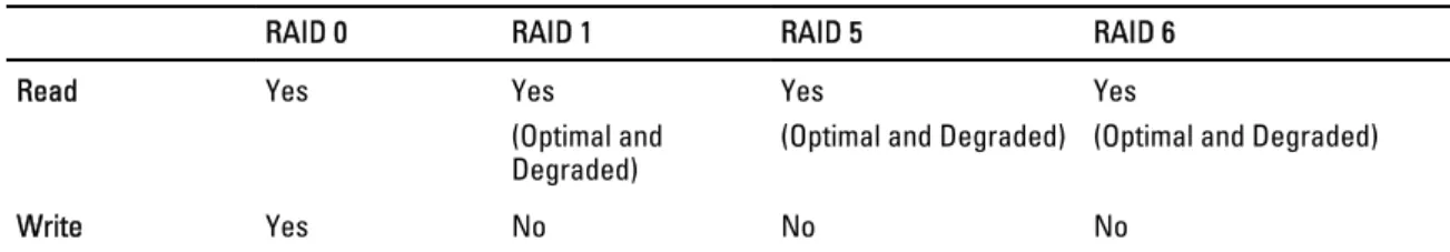
All simple virtual disks configured with write cache policy Write Through and read cache policy No Read Ahead can utilize FastPath. Only IO block sizes smaller than virtual disk’s stripe size are eligible for FastPath. In addition, there should be no background operations (rebuild, initialization) running on the virtual disks. FastPath will not be used if these operations are active.
Table 2. FastPath Eligibility Across Supported RAID Levels
RAID 0 RAID 1 RAID 5 RAID 6
Read Yes Yes
(Optimal and Degraded)
Yes
(Optimal and Degraded) Yes
(Optimal and Degraded)
Write Yes No No No
In addition, FastPath-capable virtual disks are characterized by the following:
• The presence of CacheCade virtual disks on a controller disables the FastPath capability of all eligible HDD virtual disks. Eligible SSD virtual disks are still FastPath-capable.
• Secured virtual disks are not FastPath-capable.
• The Physical Disk Power Management feature is not applicable to FastPath-capable virtual disks. • The addition or removal of a redundant path does not affect the FastPath-capability of virtual disks.
Virtual Disk Migration
The PERC H710, H710P, and H810 cards support migration of virtual disks from one controller to another without taking the target controller offline. The controller can import RAID virtual disks in optimal, degraded, or partially degraded states. You cannot import a virtual disk that is in an offline state. Disk migration pointers:
• Supports migration of VDs from PERC H700 and H800 to PERC H710P and H810 • Supports migration of volumes created within H710, H710P, or H810
• Supports migration of volumes created on H310 to H710, H710P, or H810 • Does not support migration from H700 or H800 to H310
• Does not support migration from H710, H710P, or H810 to H310
• Does not support backward migration from H310, H710, H710P, H810 to H800 and H700 NOTE: The source controller must be offline prior to performing the disk migration. NOTE: Disks cannot be migrated to older revisions or generations of the PERC cards.
NOTE: Non-RAID disks are supported only on the PERC H310 controller. Migration to any other PERC product is not supported.
NOTE: Importing secured virtual disks is supported as long as the appropriate key (LKM) is supplied or configured. When a controller detects a physical disk with an existing configuration, it flags the physical disk as foreign, and generates an alert indicating that a foreign disk was detected.
CAUTION: Do not attempt disk roaming during RLM or OCE. This causes loss of the virtual disk.
Migrating Virtual Disks
To migrate virtual disks from PERC H700 or H800 to PERC H710, H710P, or H810: 1. Turn off the system.
2. Move the appropriate physical disks from the PERC H700 or H800 card to the PERC H710, H710P, or H810 card. NOTE: If you are replacing your PERC H700 or H800 with a PERC H710, H710P, or H810 card, see the Owner’s Manual of your system at support.dell.com/manuals.
3. Boot the system and import the foreign configuration that is detected. You can do one of the following: – Press <F> to automatically import the foreign configuration.
– Enter the BIOS Configuration Utility and navigate to the Foreign Configuration View.
NOTE: For more information on accessing the BIOS Configuration Utility, see the topic Entering The BIOS Configuration Utility.
NOTE: For more information on Foreign Configuration View, see the topic Foreign Configuration View. 4. Exit the BIOS Configuration Utility and reboot the system.
5. Ensure that all the latest drivers for the PERC H710, H710P, or H810 card (available at support.dell.com) are installed.
For more information, see the topic Driver Installation.
Virtual Disk Write Cache Policies
NOTE: PERC H310 only supports Write-Through mode.
The write cache policy of a virtual disk determines how the controller handles writes to the virtual disk. Write-Back and Write-Through are the two write cache policies that can be set on virtual disks individually.
All RAID volumes are presented as Write-Through to the operating system (Windows and Linux) independent of the actual write cache policy of the virtual disk. The PERC cards manage the data in cache independently of the operating system or any applications.
NOTE: Use the Dell OpenManage storage management application or the BIOS Configuration Utility to view and manage virtual disk cache settings.
Write-Back And Write-Through
In Write-Through caching, the controller sends a data transfer completion signal to the host system when the disk subsystem has received all the data in a transaction.
In Write-Back caching, the controller sends a data transfer completion signal to the host when the controller cache has received all the data in a transaction. The controller then writes the cached data to the storage device in the
background.
The risk of using Write-Back cache is that the cached data can be lost if there is a power failure before it is written to the storage device. This risk is mitigated by using a Non-Volatile Cache on the PERC H710, H710P or H810 card.
NOTE: The default cache setting for virtual disks is Write-Back caching.
NOTE: Certain data patterns and configurations perform better with a Write-Through cache policy.
Conditions Under Which Write-Back Is Employed
Write-Back caching is used under all conditions in which the battery is present and in good condition.
Conditions Under Which Forced Write-Back With No Battery Is Employed
CAUTION: It is recommended that you use a power backup system when forcing Write-Back to ensure there is no loss of data if the system suddenly loses power.
Virtual Disk Read Cache Policies
The read policy of a virtual disk determines how the controller handles reads to that virtual disk. The read policies are: • Always Read Ahead—Allows the controller to read sequentially ahead of requested data and to store the
additional data in cache memory, anticipating that the data is required soon. This speeds up reads for sequential data, but there is little improvement when accessing random data.
• No Read Ahead—Disables the Read-Ahead capability.
• Adaptive Read Ahead—Begins using Read-Ahead if the two most recent disk accesses occurred in sequential sectors. If the read requests are random, the controller reverts to No Read Ahead mode.
NOTE: The default read cache setting for virtual disks is Adaptive Read Ahead.
Reconfiguration Of Virtual Disks
An online virtual disk can be reconfigured in ways that expands its capacity and/or change its RAID level. NOTE: Spanned virtual disks such as RAID 10, 50, and 60 cannot be reconfigured.
NOTE: Reconfiguring Virtual Disks typically impacts disk performance until the reconfiguration operation is complete.
Online Capacity Expansion (OCE) can be done in two ways:
• If there is a single virtual disk in a disk group and free space is available, the virtual disk’s capacity can be expanded within that free space.
• If a virtual disk is created and it does not use the maximum size of the disk group, free space is available. Free space is also available when a disk group’s physical disks are replaced by larger disks using the Replace Member feature. A virtual disk's capacity can also be expanded by performing an OCE operation to add more physical disks. RAID Level Migration (RLM) refers to changing a virtual disk’s RAID level. Both RLM and OCE can be done at the same time so that a virtual disk can simultaneously have its RAID level changed and its capacity increased. When a RLM/OCE operation is complete, a reboot is not required. See the following table for a list of RLM/OCE possibilities. The source RAID level column indicates the virtual disk RAID level before the RLM/OCE and the target RAID level column indicates the RAID level after the operation has completed.
NOTE: If the controller already contains the maximum number of virtual disks, you cannot perform a RAID level migration or capacity expansion on any virtual disk.
NOTE: The controller changes the write cache policy of all virtual disks undergoing a RLM/OCE to Write-Through until the RLM/OCE is complete.
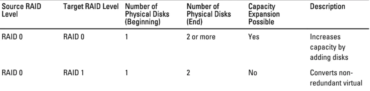
Table 3. RAID Level Migration Source RAID
Level Target RAID Level Number of Physical Disks (Beginning) Number of Physical Disks (End) Capacity Expansion Possible Description
RAID 0 RAID 0 1 2 or more Yes Increases
capacity by adding disks
RAID 0 RAID 1 1 2 No Converts
Source RAID
Level Target RAID Level Number of Physical Disks (Beginning) Number of Physical Disks (End) Capacity Expansion Possible Description disk into a mirrored virtual disk by adding one disk. RAID 0 RAID 5 1 or more 3 or more Yes At least one disk
needs to be added for distributed parity data.
RAID 0 RAID 6 1 or more 4 or more Yes At least two disks need to be added for dual
distributed parity data.
RAID 1 RAID 0 2 2 or more Yes Removes
redundancy while increasing capacity.
RAID 1 RAID 5 2 3 or more Yes Maintains
redundancy while doubling capacity.
RAID 1 RAID 6 2 4 or more Yes Two disks
required to be added for distributed parity data.
RAID 5 RAID 0 3 or more 3 or more Yes Converts to a non-redundant virtual disk and reclaims disk space used for distributed parity data.
RAID 5 RAID 5 3 or more 4 or more Yes Increases
capacity by adding disks RAID 5 RAID 6 3 or more 4 or more Yes At least one disk
needs to be added for dual distributed parity data.
RAID 6 RAID 0 4 or more 4 or more Yes Converts to a non-redundant virtual
Source RAID
Level Target RAID Level Number of Physical Disks (Beginning) Number of Physical Disks (End) Capacity Expansion Possible Description disk space used for distributed parity data. RAID 6 RAID 5 4 or more 4 or more Yes Removes one set
of parity data and reclaims disk space used for it.
RAID 6 RAID 6 4 or more 5 or more Yes Increases
capacity by adding disks. NOTE: The total number of physical disks in a disk group cannot exceed 32. You cannot perform RAID level migration and expansion on RAID levels 10, 50, and 60.
Fault Tolerance
The list of features of the PERC cards that provide fault tolerance to prevent data loss is as follows: • Support for Self Monitoring and Reporting Technology (SMART)
• Support for Patrol Read
• Redundant path support (for PERC H810 only) • Physical disk failure detection
• Physical disk rebuild using hot spares • Controller Cache Preservation
• Battery and Non-Volatile Cache backup of controller cache to protect data • Detection of batteries with low charge after boot up
The next sections describe some methods to achieve fault tolerance.
The SMART Feature
The SMART feature monitors certain physical aspects of all motors, heads, and physical disk electronics to help detect predictable physical disk failures. SMART-compliant physical disks have attributes for which data can be monitored to identify changes in values and determine whether the values are within threshold limits. Many mechanical and electrical failures display some degradation in performance before failure.
A SMART failure is also referred to as a predicted failure. There are numerous factors that relate to predicted physical disk failures, such as a bearing failure, a broken read/write head, and changes in spin-up rate. In addition, there are factors related to read/write surface failure, such as seek error rate and excessive bad sectors.
NOTE: For detailed information on SCSI interface specifications, see t10.org and for detailed information on SATA interface specifications, see t13.org.
Automatic Replace Member With Predicted Failure
A Replace Member operation can occur when there is a SMART predictive failure reporting on a physical disk in a virtual disk. The automatic Replace Member is initiated when the first SMART error occurs on a physical disk that is part
of a virtual disk. The target disk needs to be a hot spare that qualifies as a rebuild disk. The physical disk with the SMART error is marked as failed only after the successful completion of the Replace Member. This avoids putting the array in degraded status.
If an automatic Replace Member occurs using a source disk that was originally a hot spare (that was used in a rebuild), and a new disk added for the Replace Member operation as the target disk, the hot spare reverts to the hot spare state after a successful Replace Member operation.
NOTE: To enable the automatic Replace Member, use the Dell OpenManage storage management application. For more information on automatic Replace Member, see the topic Dell OpenManage Storage Management. For information on manual Replace Member, see the topic Replacing An Online Physical Disk.
Patrol Read
The Patrol Read feature is designed as a preventative measure to ensure physical disk health and data integrity. Patrol Read scans for and resolves potential problems on configured physical disks. The Dell OpenManage storage
management application can be used to start Patrol Read and change its behavior. The following is an overview of Patrol Read behavior:
• Patrol Read runs on all disks on the controller that are configured as part of a virtual disk, including hot spares. • Patrol Read does not run on physical disks that are not part of a virtual disk or are in Ready state.
• Patrol Read adjusts the amount of controller resources dedicated to Patrol Read operations based on outstanding disk I/O. For example, if the system is busy processing I/O operation, then Patrol Read uses fewer resources to allow the I/O to take a higher priority.
• Patrol Read does not run on any disks involved in any of the following operations: – Rebuild
– Replace Member
– Full or Background Initialization – CC
– RLM or OCE
NOTE: By default, Patrol Read automatically runs every seven days on configured SAS and SATA hard drives. Patrol Read is not necessary on SSD and is disabled by default.
For more information on Patrol Read, see the Dell OpenManage documentation at dell.com/support/manuals.
Redundant Path Support (For PERC H810 Only)
The PERC H810 adapter can detect and use redundant paths to disks contained in enclosures. This provides the ability to connect two SAS cables between a controller and an enclosure for path redundancy. The controller is able to tolerate the failure of a cable or Enclosure Management Module (EMM) by utilizing the remaining path.
When redundant paths exist, the controller automatically balances I/O load through both paths to each disk. Load balancing increases throughput to virtual disks in storage enclosures and is automatically turned on when redundant paths are detected. The ability to load balance I/O can be disabled using the Dell OpenManage storage management application.
To set up your hardware to support redundant paths, see the topic Setting Up Redundant Path Support On The PERC H810 Adapter.
Physical Disk Failure Detection
Failed physical disks are detected and rebuilds automatically start to new disks that are inserted into the same slot. Automatic rebuilds can also happen transparently with hot spares. If you have configured hot spares, the controllers automatically try to use them to rebuild failed physical disks.
Using Persistent Hot Spare Slots
NOTE: The persistent hot spare slot feature is disabled by default.
The PERC H310, H710, H710P, and H810 cards can be configured so that the system backplane or storage enclosure disk slots are dedicated as hot spare slots. This feature can be enabled using the Dell OpenManage storage management application.
Once enabled, any slots with hot spares configured automatically become persistent hot spare slots. If a hot spare disk fails or is removed, a replacement disk that is inserted into the same slot automatically becomes a hot spare with the same properties as the one it is replacing. If the replacement disk does not match the disk protocol and technology, it does not become a hot spare.
For more information on persistent hot spares, see the Dell OpenManage documentation at dell.com/support/manuals.
Physical Disk Hot Swapping
NOTE: To check if the backplane supports hot swapping, see the Owner’s Manual of your system.
Hot swapping is the manual replacement of a disk while the PERC H310, H710, H710P, or H810 cards are online and performing their normal functions. The following requirements must be met before hot swapping a physical disk:
• The system backplane or enclosure must support hot swapping for the PERC H310, H710, H710P or H810 cards to support hot swapping.
• The replacement disk must be of the same protocol and disk technology. For example, only a SAS hard drive can replace a SAS hard drive; only a SATA SSD can replace a SATA SSD.
• The replacement disk must be of equal or greater capacity than the one it is replacing.
Using Replace Member And Revertible Hot Spares
The Replace Member functionality allows a previously commissioned hot spare to be reverted to a usable hot spare. When a disk failure occurs within a virtual disk, an assigned hot spare (dedicated or global) is commissioned and begins rebuilding until the virtual disk is optimal. After the failed disk is replaced (in the same slot) and the rebuild to the hot spare is complete, the controller automatically starts to copy data from the commissioned hot spare to the newly-inserted disk. After the data is copied, the new disk is a part of the virtual disk and the hot spare is reverted to being a ready hot spare. This allows hot spares to remain in specific enclosure slots. While the controller is reverting the hot spare, the virtual disk remains optimal.
NOTE: The controller automatically reverts a hot spare only if the failed disk is replaced with a new disk in the same slot. If the new disk is not placed in the same slot, a manual Replace Member operation can be used to revert a previously commissioned hot spare.
NOTE: A Replace Member operation typically causes a temporary impact to disk performance. Once the operation completes, performance returns to normal.
Controller Cache Preservation
The controller is capable of preserving its cache in the event of a system power outage or improper system shutdown. The PERC H710, H710P, and H810 controllers are attached to a Battery Backup Unit (BBU) that provides backup power during system power loss to preserve the controller's cache data.
Cache Preservation With Non-Volatile Cache (NVC)
In essence, the NVC module allows controller cache data to be stored indefinitely. If the controller has data in the cache memory during a power outage or improper system shutdown, a small amount of power from the battery is used to transfer cache data to a non-volatile flash storage where it remains until power is restored and the system is booted.
Recovering Cache Data
The dirty cache LED that is located on the H710 and H810 cards can be used to determine if cache data is being preserved.
If a system power loss or improper system shutdown has occurred: 1. Restore the system power.
2. Boot the system.
3. To enter the BIOS Configuration Utility, select Managed Preserved Cache in the controller menu. If there are no virtual disks listed, all preserved cache data has been written to disk successfully.
Battery Transparent Learn Cycle
NOTE: Batteries are only supported on PERC H710, H710P, and H810 cards.
A transparent learn cycle is a periodic operation that calculates the charge that is remaining in the battery to ensure there is sufficient energy. The operation runs automatically, and causes no impact to the system or controller performance.
The controller automatically performs the Transparent Learn Cycle (TLC) on the battery to calibrate and gauge its charge capacity once every 90 days. The operation can be performed manually, if required.
NOTE: Virtual disks stay in Write Back mode, if enabled, during transparent learn cycle. When the TLC completes, the controller sets the next TLC to +90 days.
TLC Time Frame
The time frame for completion of a learn cycle is a function of the battery charge capacity and the discharge and charge currents used. For PERC H710 or H810 cards, the expected time frame for completion of a learn cycle is approximately seven hours.
Conditions For Replacing The Battery
The PERC battery is marked Failed when the state or health of the battery is declared bad. If battery is declared failed then the firmware runs learn cycles in subsequent reboots until the battery is replaced. The virtual disk then transitions to Write Back mode.
3
Deploying The PERC Card
CAUTION: Many repairs may only be done by a certified service technician. You should only perform
troubleshooting and simple repairs as authorized in your product documentation, or as directed by the online or telephone service and support team. Damage due to servicing that is not authorized by Dell is not covered by your warranty. Read and follow the safety instructions that came with the system.
NOTE: For information on removing and reinstalling system parts, see the Owner's Manual of the system at dell.com/support/manuals.
NOTE: For more information on your storage controller, see the relevant storage controller documentation at dell.com/support/manuals.
This document provides a set of high level installation and removal instructions for the following Dell PowerEdge RAID Controllers (PERC):
• PERC H310 Adapter • PERC H310 Mini Monolithic • PERC H310 Mini Blade • PERC H710 Adapter • PERC H710P Adapter • PERC H710 Mini Monolithic • PERC H710P Mini Monolithic • PERC H710 Mini Blade • PERC H710P Mini Blade • PERC H810 Adapter
Removing The PERC Controller
To remove the PERC controller:
1. Perform a controlled shutdown of the system and attached peripherals. 2. Disconnect the system from the electrical outlet and remove the system cover. 3. Remove the storage controller from the PCIe slot of the system.
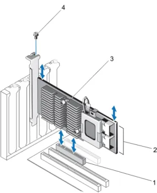
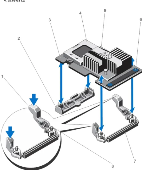
CAUTION: When removing or replacing the PERC Mini Monolithic Controller, hold the card by its edges marked by the blue touch points. Do not handle the card while holding the battery or the heatsink. For more information, see to the relevant figures below.
Figure 1. Removing and Installing the PERC Adapter 1. PCIe slot
2. SAS cable connectors (2) 3. PERC adapter
4. screw (1)
1. release lever (2)
2. PERC stack-up connector 3. PERC mini blade controller 4. screws (2)
Figure 3. Removing and Installing the PERC Mini Monolithic Controller 1. release lever (2)
2. storage-controller card holder 3. storage controller card 4. battery
5. heatsink
6. touch points (2)
7. storage-controller card connector on the system board
8. guide pins (2)
Installing The PERC Controller
To install the PERC controller:
3. Install the storage controller in the appropriate controller slot and connect all the cables to the storage controller. CAUTION: When removing or replacing the PERC Mini Monolithic Controller, hold the card by its edges marked by the blue touch points. Do not handle the card while holding the battery or the heatsink. For more information, see the relevant figures in Removing The PERC Controller.
4. Replace the system cover.
5. Reconnect the system to its electrical outlet and turn the system on, including any attached peripherals.
Support For Internal Multiple Controllers
On PowerEdge systems with dual bays (backplanes), the disk drives are managed by independent PERC H710P cards. The PERC H710P cards do not share the disks or the RAID volumes. A drive can be identified using the following as guideline: Controller: Bay/Backplane: Slot.
Setting Up Redundant Path Support On The PERC H810 Adapter
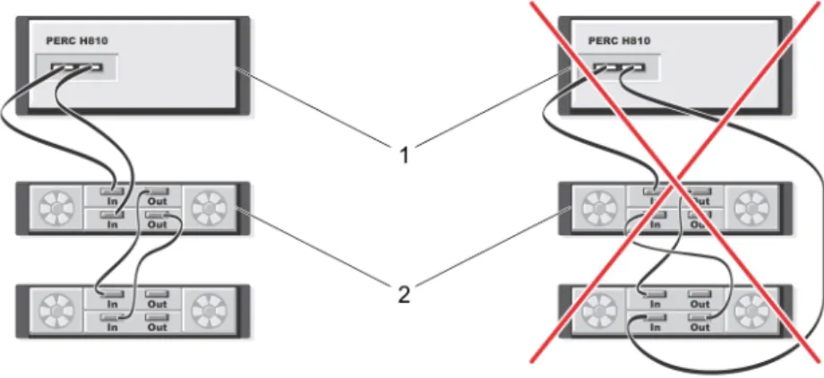
The PERC H810 card can detect and use redundant paths to disks contained in enclosures. With redundant paths to the same device, if one path fails, another path can be used to communicate between the controller and the device. To set up a configuration with redundant paths, both ports on a controller must be cabled to the In ports of a single enclosure.
To add multiple enclosures, both Out ports of the first enclosure must be cabled to the In ports of the next enclosure. If the connection between an Out port on the controller and an In port on an enclosure fails, an alternate path exists through the second Out port on the controller and the second In port on the enclosure. For more information, see the following figure.
NOTE: The PERC H810 card supports redundant paths when used with Dell PowerVault MD1200 and Dell PowerVault MD1220 disk storage enclosures.
Perform the following steps to configure the hardware to utilize redundant paths on the PERC H810 card: 1. Set up an enclosure on the PERC H810 card.
2. Connect two SAS cables from the Out ports on your PERC H810 card to the In ports of the external enclosure. For more information, see the following figure.
NOTE: For information on Unified Mode, see the enclosure documentation that was shipped with the enclosure.
3. To add multiple enclosures, cable both Out ports of the first enclosure to both In ports of the next enclosure. After you set up the hardware, the controller detects the redundant paths and automatically utilizes them to balance the I/O load.
Reverting To Single Path Support From Redundant Path Support For
PERC H810
If you need to revert to single path support from redundant path support, shut down the system and remove the exact same cables that were added to support redundant path support, leaving only one connection between the controller and enclosures. After you remove the cable and power up the system, ensure that there are no warning messages during boot, and that all virtual disks are online and optimal. If you are using Dell OpenManage, see the Dell OpenManage documentation at dell.com/support/manuals for additional instructions.
CAUTION: If you remove any cables other than the ones added to enable redundant path support, the enclosure and disks can get disconnected, and virtual disk may fail.
Perform the following steps to configure the hardware to utilize redundant paths on the PERC H810 card: 1. Set up an enclosure on the PERC H810 card.
2. Connect two SAS cables from the Out ports on your PERC H810 card to the In ports of the external enclosure. For more information, see the following figure.
NOTE: For information on Unified Mode, see the enclosure documentation that was shipped with the enclosure.
3. To add multiple enclosures, cable both Out ports of the first enclosure to both In ports of the next enclosure. 4. After you set up the hardware, the controller detects the redundant paths and automatically utilizes them to
balance the I/O load.
Figure 4. Redundant Path Support Configuration With Two Enclosures 1. server
4
Driver Installation
The Dell PowerEdge RAID Controller (PERC) H310, H710, H710P, and H810 cards require software drivers to operate with the supported operating systems.
This chapter contains the procedures for installing the drivers for the PERC H310, H710, H710P, and H810 cards. NOTE: For more information on VMware ESX drivers, see the VMware ESX documentation at dell.com/support/ manuals.
NOTE: To check operating system compatibility, see dell.com/support/manuals. The two methods for installing a driver discussed in this chapter are:
Installing a driver during operating system
installation
Use this method if you are performing a new installation of the operating system and want to include the drivers.
Updating existing drivers
Use this method if the operating system and the PERC H310, H710, H710P, and H810 family of controllers are already installed and you want to update to the latest drivers.
Pre-Installation Requirements For Windows Driver Installation
Before you install the operating system:
• Read the Microsoft Getting Started document that shipped with your operating system.
• Ensure that your system has the latest BIOS, firmware, and driver updates. If required, download the latest BIOS, firmware, and driver updates fromdell.com/support.
• Create a device driver media (diskette, USB drive, CD, or DVD).
Creating The Device Driver Media For Windows Driver Installation
Use one of the following two methods to create the device driver media:
• Downloading drivers from the Dell systems service and diagnostic tools media for Windows • Downloading drivers from the Dell support website for Windows
Downloading Drivers From The Dell Systems Service And Diagnostic Tools Media For
Windows
To download drivers from the Dell Systems Service and Diagnostic Tools media: 1. Insert the Dell Systems Service and Diagnostics Tools media in a system.
The Welcome to Dell Service and Diagnostic Utilities screen is displayed. 2. Select your system model and operating system (Microsoft Windows Server 2008).
4. From the list of drivers displayed, select the driver you require. Select the self-extracting zip file and click Run. Copy the driver to a diskette drive, CD, DVD, or USB drive. Repeat this step for all the drivers you require.
5. During the operating system installation, use the media that you created with the Load Driver option to load mass storage drivers. For more information on reinstalling the operating system, see the relevant section for your operating system below.
Downloading Drivers From The Dell Support Website For Windows
To download drivers from the Dell Support website: 1. Go to dell.com/support.
2. Select your line of business.
3. In the Popular support tools section, click Drivers and Downloads.
4. Enter the service tag of your system in the Choose by Service Tag to get started field or select Choose from a list of all Dell products.
5. Select the System Type, Operating System, and Category from the drop-down list. The drivers that are applicable to your selection are displayed.
6. Download the drivers that you require to a diskette drive, USB drive, CD, or DVD.
7. During the operating system installation, use the media that you created with the Load Driver option to load mass storage drivers. For more information on reinstalling the operating system, see the relevant section for your operating system below.
Installing Driver During a Windows Server 2008/2008 R2 Installation
To install the driver:
1. Boot the system using the Windows Server 2008, or Windows Server 2008 R2 media.
2. Follow the on-screen instructions until you reach Where do you want to install Windows Server 2008 window and then select Load driver.
3. The system prompts you to insert the media. Insert the installation media and browse to the proper location. 4. Select the appropriate PERC H310, H710, H710P, or H810 card from the list, click Next and continue installation.
Installing Windows Server 2008/2008 R2 For A New RAID Controller
Perform the following steps to configure the driver for the RAID controller on a system that already has Windows installed:
1. Turn off the system.
2. Install the new RAID controller in the system.
For detailed instructions on installing and cabling the RAID controller in the system, see the topic Deploying The PERC Card.
3. Turn on the system.
The Found New Hardware Wizard screen displays the detected hardware device. 4. Click Next.
5. On the Locate device driver screen, select Search for a suitable driver for my device and click Next. 6. Browse and select the drivers from the Locate Driver Files screen.
7. Click Next.
The wizard detects and installs the appropriate device drivers for the new RAID controller. 8. Click Finish to complete the installation.
9. Reboot the system when prompted.
Updating Existing Windows Server 2008 Or Windows Server 2008 R2
NOTE: Close all applications on your system before you update the driver. 1. Insert the media (CD, DVD, or USB drive) containing the driver.
2. Select Start → Settings → Control Panel → System. The System Properties screen is displayed.
NOTE: The path to System might vary depending on the operating system family. 3. Click on the Hardware tab.
4. Click Device Manager.
The Device Manager screen is displayed.
NOTE: The path to Device Manager might vary depending on the operating system family.
5. Expand SCSI and RAID Controllers by double-clicking the entry or by clicking on the plus symbol next to SCSI and RAID Controller.
NOTE: In Windows 2008 and Windows 2008 R2, the PERC card is listed under Storage Controllers. 6. Double-click the RAID controller for which you want to update the driver.
7. Click the Driver tab and click Update Driver.
The screen to update the device driver wizard is displayed. 8. Select Install from a list or specific location.
9. Click Next.
10. Follow the steps in the wizard and browse to the location of the driver files. 11. Select the INF file from the driver media (CD, DVD, or other media). 12. Click Next and continue the installation steps in the wizard.
13. Click Finish to exit the wizard and reboot the system for the changes to take place.
NOTE: Dell provides the Dell Update Package (DUP) to update drivers on systems running Windows Server 2008 or Windows Server 2008 R2 operating system. DUP is an executable application that updates drivers for specific devices. DUP supports command line interface and silent execution. For more information, see dell.com/support.
Updating The Linux Driver
NOTE: PERC H310/H710/H710P/H810, PERC H700/H800 cards and both the PERC 5 and PERC 6 family of controllers use the same driver and do not require separate driver installations.
Use the procedures in this section to update the driver for Linux. To ensure that you have the current version of the driver, download the updated Linux driver from dell.com/support.
NOTE: The driver update disk (DUD) images are created only for those operating system releases in which the native (in-box) driver is insufficient for installation. In the event that an operating system is being installed with a corresponding DUD image, follow the instructions below. If not, proceed with using the native device driver and
Installing Or Updating The RPM Driver Package With DKMS Support
NOTE: This procedure is applicable for Red Hat Enterprise Linux 5 SP7 and SUSE Enterprise Linux 10 SP4. NOTE: For SUSE Enterprise Linux 10 SP4, immediately following the operating system installation, download the latest driver from dell.com/support, and update the driver using the procedures detailed in this section. Perform the following steps to install the RPM package with DKMS support:
1. Uncompress the gzipped tarball driver release package.
2. Install the DKMS package using the command: rpm –ihv megaraid_sas- <version> .noarch.rpm. 3. Install the driver package using the command: rpm –ihv megaraid_sas- <version> .noarch.rpm.
NOTE: Use rpm -Uvh <package name> when updating an existing package.
4. If the previous device driver is in use, you must reboot the system for the updated driver to take effect. 5. Verify that the driver has been loaded with the following system commands: modinfo megaraid_sas and dkms
status.
Installing Or Updating The RPM Driver Package With KMOD Support
NOTE: This procedure is applicable for Red Hat Enterprise Linux 6 SP2. Perform the following steps to install the RPM package with KMOD support: 1. Uncompress the gzipped tarball driver release package.
2. Install the driver package using the command: rpm –ihv kmodmegaraid_ sas-<version>.rpm. NOTE: Use rpm -Uvh <package name> when upgrading an existing package.
3. If the previous device driver is in use, you must reboot the system for the updated driver to take effect. 4. Verify that the driver has been loaded with the following system commands: modinfo megaraid_sas.
Installing Or Updating The RPM Driver Package With KMP Support
NOTE: This procedure is applicable for SUSE Enterprise Linux 11 SP2. Perform the following steps to install the RPM package with KMP support: 1. Uncompress the gzipped tarball driver release package.
2. Install the driver package using the command: rpm –ihv kmpmegaraid_ sas- <version>.rpm. NOTE: Use rpm -Uvh <package name> when updating an existing package.
3. If the previous device driver is in use, you must reboot the system for the updated driver to take effect. 4. Verify that the driver has been loaded with the following system commands: modinfo megaraid_sas.
Upgrading The Kernel
When upgrading to a new kernel, you must reinstall the DKMS-enabled driver packages. Perform the following steps to update or install the driver for the new kernel:
1. In a terminal window, type the following: dkms build -m <module_name> – v <module version> – k <kernel version> dkms install -m <module_name> – v <module version> – k <kernel version>.
You see a message similar to the following one: <driver name>, <driver version>, <new kernel version>: installed.
5
Management Applications For PERC Cards
Dell OpenManage Storage Management applications enable you to manage and configure the RAID system, create and manage multiple disk groups, control and monitor multiple RAID systems, and provide online maintenance. The management applications for PERC H310, H710, H710P, and H810 include:
• Dell OpenManage Storage Management • BIOS Configuration Utility (<Ctrl> <R>)
• Unified Extensible Firmware Interface (UEFI) RAID Configuration Utility
NOTE: Dell serial-attached SCSI (SAS) RAID Storage Manager is not supported for SED management.
Dell OpenManage Storage Management
The Dell OpenManage Storage Management is a storage management application for Dell systems that provides enhanced features for configuring a system's locally-attached RAID and Non-RAID disk storage. The Dell OpenManage storage management application enables you to perform controller and enclosure functions for all supported RAID controllers and enclosures from a single graphical or command-line interface without requiring the use of the controller BIOS utilities. The graphical user interface (GUI) is wizard-driven with features for novice and advanced users, and detailed online help. Using the Dell OpenManage storage management application, you can protect your data by configuring data-redundancy, assigning hot spares, or rebuilding failed physical disks. The command line interface available on selected operating systems to perform RAID management tasks is fully featured and scriptable.
NOTE: For more information, see the Dell OpenManage Storage Management User's Guide at dell.com/support/ manuals.
BIOS Configuration Utility
The BIOS Configuration Utility, also known as <Ctrl> <R>, is a storage management application embedded on the PERC H310, H710, H710P, and H810 cards that configures and maintains RAID disk groups and virtual disks. <Ctrl> <R> is independent of the operating system.
NOTE: Use the BIOS Configuration Utility (<Ctrl> <R>) for initial setup and disaster recovery. You can use advanced features through Dell OpenManage storage management application and Dell SAS RAID storage manager. The following sections provide information about using the BIOS Configuration Utility (<Ctrl> <R>). For more information, see the online help option by pressing <F1> in the BIOS Configuration Utility (<Ctrl> <R>).
NOTE: The PERC PER H310, H710, H710P, and H810 card configuration utility refreshes the screen to show changes to information. The refresh occurs when you press <F5>or every 15 seconds.
Entering The BIOS Configuration Utility
A BIOS screen displays information about the controller and configuration. 2. During startup, press <Ctrl> <R> when prompted by the BIOS screen.
3. Use the arrow keys to select the RAID controller you want to configure, and press <Enter> to access the management menus for the controller.
If there is only one controller, the Virtual Disk Management screen for that controller is displayed. If there is more than one controller, the main menu screen is displayed. The screen lists the RAID controllers.
NOTE: You can access multiple controllers through the BIOS Configuration Utility (<Ctrl> <R>) by pressing <F12>.
NOTE: You can access PERC H700, H800, H310, H710, H710P, or H810 cards from the same BIOS if the PERC 6/ H700/H800 firmware is 6.2.0-0013 or later.
Exiting The Configuration Utility
To exit the BIOS Configuration Utility (<Ctrl> <R>) 1. Press <Esc> on any menu screen.
If there is only one controller, then a dialog box is displayed to confirm your choice. 2. Select OK to exit and press <Enter>.
If multiple controllers are present, then the <Esc> key brings you to the Controller Selection screen. 3. Press <Esc> again to reach the exit screen.
A dialog box is displayed to confirm your choice. 4. Select OK to exit and press <Enter>.
Menu Navigation Controls
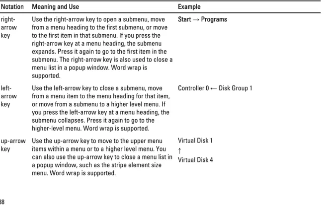
The following table displays the menu keys you can use to move between the different screens in the BIOS Configuration Utility (<Ctrl> <R>).
Table 4. Menu Navigation Keys
Notation Meaning and Use Example
right-arrow key
Use the right-arrow key to open a submenu, move from a menu heading to the first submenu, or move to the first item in that submenu. If you press the right-arrow key at a menu heading, the submenu expands. Press it again to go to the first item in the submenu. The right-arrow key is also used to close a menu list in a popup window. Word wrap is
supported.
Start → Programs
left-arrow key
Use the left-arrow key to close a submenu, move from a menu item to the menu heading for that item, or move from a submenu to a higher level menu. If you press the left-arrow key at a menu heading, the submenu collapses. Press it again to go to the higher-level menu. Word wrap is supported.
Controller 0 ← Disk Group 1
up-arrow
key Use the up-arrow key to move to the upper menu items within a menu or to a higher level menu. You can also use the up-arrow key to close a menu list in a popup window, such as the stripe element size menu. Word wrap is supported.
Virtual Disk 1 ↑