Interactive Web Based Animation Software: An Efficient Way to Increase the
Engineering Student’s Fundamental Understanding of Particle Kinematics
and Kinetics
AbstractAnimation software for an introductory Dynamics course has been developed, which may be a supplement to the proposed text: Riley, Sturges, Stanley “Dynamics”, 3rd Edition (Wiley and Sons, Inc. New York). This interactive software is unique because each animation is directly linked to a homework problem and no programming is required of the user. The animations are web-based (hard-coded in Adobe Flash Action Script), so no external computer programs are needed.
The software was piloted in two sections of Dynamics during the fall term of 2007, where it was used for both in-class demonstrations and homework assignments. Approximately 70 students were surveyed at the end of the term regarding the effectiveness of the software. All of the students describe themselves as visual learners and agree that animations, in some form, will be regularly used in engineering classes in the near future. Most students think that their overall understanding of particle kinematics and kinetics was significantly improved by using the program. They consider the software easy to use and recommended it to instructors who teach introductory Dynamics classes.
In this paper, the software functionality will be detailed. The results of the survey will be analyzed and the pedagogical advantages will be evaluated.
1. Introduction
In current Dynamics text books, most homework problems require the student to solve for a given variable at an instance in space and time. The professor typically assigns a set of
homework problems and the students solve each problem by hand. The student knows that his or her calculations are correct by checking answers in the back of the book.
Something similar happens when problems are solved in the classroom. The professor puts the problem in simple words, sets it up, and calculates the correct answer.
In reality, though, the subject of particle Dynamics is the study of motion and not the calculation of a particle’s point at a particular instance in time. It is the author’s opinion that this
differentiation may be lost in the traditional classroom and that computer animations will help close this gap.
The animation of Dynamics problems can be done via several commercially available software programs. These packages include, for example, Working Model, ADAMS, and Dynamic Simulation via Autodesk Inventor Professional software. Animations created by these software packages can easily be converted into computer-based movies, which can be played on any computer. For interactivity, the software must be loaded on the user’s computer, which can be expensive and inconvenient. If a professor wants to use any of these software packages to create
interactive Dynamics animations, he or she must take the time to create each individual problem, which can be overwhelming
Web based interactive animation software may be developed either by creating Java Applets or by writing code in Adobe Flash Action Script. A popular package of interactive web-based software has been developed to animate Statics and Mechanics of Materials problems1,2,3,4,5. The software, MecMovies, contains approximately 150 modules that can be accessed via the
internet6. In a recent study, it was found, “Slight to modest gains were seen in student learning and retention of material in some mechanics of materials topics, as evidenced by some
improvement in the quiz scores of the students who used MecMovies”7. Other interactive web-based software has been created to enhance learning in mechanical engineering classes8,9,10. None of the animations stated are directly linked to any homework problem in a textbook. The reason that comprehensive and interactive web-based animation software for educators has not been developed on a mass scale is probably due to cost. For instance, the development of commercial animations, such as Pixar’s Toy Story, cost approximately $20M per run-time hour11,12 and a modern video game costs approximately $40M to develop13.
The web-based animation software explained in this paper is unique, practical, and economical for the following reasons:
• There is no software to install.
• The animations can be played on virtually any computer; the Adobe Flash Player is installed on 98.8% of internet-enabled desktops worldwide14.
• Each animation is directly linked to a homework problem or sample problem in the text. • There is absolutely no programming required of the user.
• The software is extremely easy to use; the controls are similar to those of a DVD player. • Because the program is “hard-coded” in Adobe Flash Action Script, there is an abundance of
control in the advancement of the software package.
• The cost and time of development is relatively low because all images are duplicated directly from the textbook and intricate graphics and backgrounds are not included in the animations.
2. Software Overview
There are many categories of particle kinematics and kinetics problems that are included as part of the animation software; many homework and example problems are included in each
category. Categories include, for example:
• 2D-XY Kinematics: Two Dimensional (2-D) Kinematics in the Rectilinear Coordinate System (C.S.)
• 2D-nt Kinematics: 2-D Kinematics in the Normal-Tangential C.S.
• BLOCK-RAMP Kinetics: Kinetics of a Block Sliding Up/Down a Ramp (with friction) For the purposes of the explanation of the software, a problem in the category of 2D-XY Kinematics is detailed next.
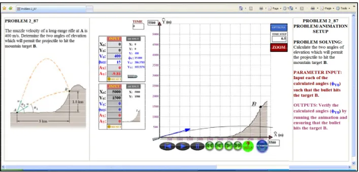
The main problem page has three sections (Figure 1). The left hand side displays the problem, exactly as it appears in the text. The center portion of the page holds the animation, specifically developed for the given problem.
The right hand side of the page gives the student a roadmap regarding what is required of him or her. Under the heading PROBLEM SOLVING, the problem is re-worded in simple terms. PARAMETER INPUT indicates what inputs are required, and OUTPUTS indicates what the student needs to ensure that his or her calculations are correct.
Each animation contains between one and three objects. In the given problem, the two objects are the bullet and the target.
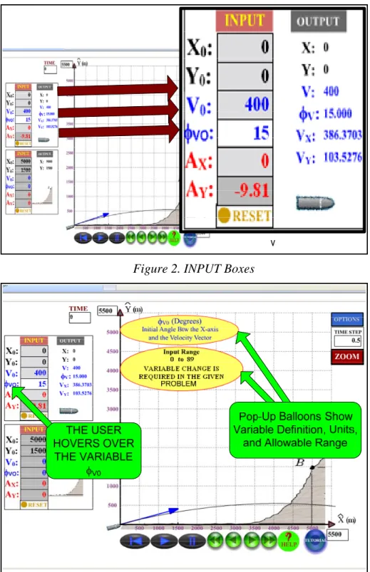
Each object has INPUT variables which may be changed by the user (Figure 2). INPUT variables with a white background must be changed by the user (in the case of the bullet, φV0). INPUT
variables with a light grey background already have the correct input values entered. These values may be changed by the user, if desired, for "what-if" analyses (in the case of the bullet, X0, Y0, V0, and AX). INPUT variables with a dark grey background also have the correct input
values entered, but they may not be changed by the user (in the case of the bullet, AY). All
variables are color coded; variables associated to the particle’s position are black, those related to the velocity are blue, and those associated to the acceleration are red.
Figure 1. Screen Shot: 2-D XY Kinematics Problem
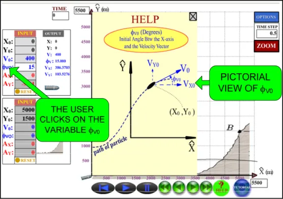
When the user hovers the mouse over an INPUT variable, pop-up balloons indicate the variable definition, the units, and the range of allowable values. For instance, φV0 is defined as the angle
between the initial velocity vector and the x-axis, with an allowable range of 0º to 89º. This variable must be changed by the user in the given problem (Figure 3).
If the user wants a pictorial representation of the variable, he or she may click on the variable and a pop-up box will provide this information (Figure 4).
Figure 2. INPUT Boxes
Figure 3. INPUT Variable Definition/Range
Just to the right of the INPUT values are the OUTPUT variables. The six OUTPUT variables, chosen specifically for this problem are X, Y, V, φV, VX, and VY (Figure 2). As with the INPUT
variables, the variable definition and units are displayed when the user hovers the mouse over the given variable.
Figure 4. Pictorial Variable Representation
Figure 5. OUTPUT Variable Menu
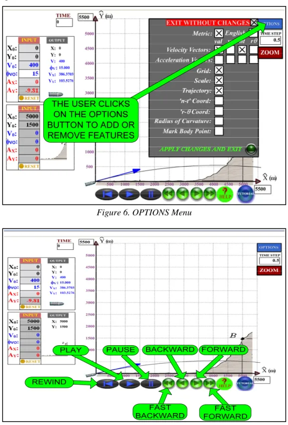
If the user would like to add or delete OUTPUT variables, he or she can click on the OUTPUT button and a pop-up screen appears (Figure 5). Several options are available to the user; these can be viewed and changed by clicking the OPTIONS button (Figure 6). And finally, the
controls of the animation are familiar to any user; they are similar to those of a modern DVD player (Figure 7).
Figure 6. OPTIONS Menu
TRAJECTORY VELOCITY
VECTOR
DEFAULT VALUE OF V0(15 deg)
3. Problem Solving Methodology
Following is an example of how a student can use the software.
As shown in Figures 8 and 9, the student must solve for the two initial velocity vector angles that will cause the bullet to travel from point A to point B, with an initial velocity magnitude of 400 m/sec.
Figure 8. Problem With Default INPUT Values
Figure 9. Problem With the Calculated INPUT Value of φV0 = 32.1°
In an initial attempt, the student incorrectly calculates the lower angle to be 32.1º. The calculated value is entered in the appropriate INPUT box in the animation. Figures 8 and 9 display the animation program with the default value of φV0 = 15° and the calculated value of φV0 = 32.1°,
is changed from its default value. Also, see how the velocity vector and the trajectory change with the two values of φV0.
The student hits the PLAY button to check to his or her computations. The calculated value is shown to be incorrect by the popup balloon that reads “MISSED!” (Figure 10). The student recalculates φV0 to be 26.1° and hits the PLAY button. The animation confirms that this
calculation is correct (Figure 11). The red pop-up box shows that a successful hit requires that the bullet lands within 10 m of the target. The actual distance between the bullet and the target is 0.87 m, which indicates success. This reinforces that engineering problems are not solved
exactly. There is always an envelope of precision that must be met for an acceptable answer to be obtained.
Figure 10. Incorrect INPUT Value of φV0= 32. 1°
1a) I Consider Myself to be a Visual Learner. 0% 10% 20% 30% 40% 50% 60% 70% 80% Strongly Agree
Agree Neutral Disagree Strongly Disagree
1b) I Believe That Animations Will be Used in the Future. 0% 10% 20% 30% 40% 50% 60% Strongly Agree
Agree Neutral Disagree Strongly Disagree 1a) I consider myself to be visual learner; I comprehend engineering mechanics problems better when I can see
the phenomena
1b) In the not too distant future, animations will be a part of most engineering disciplines.
1c) The animations software enhances my overall understanding of particle kinematics and kinetics.
1d) The animations program instills a reality check; it enables me to comprehend the magnitude of how incorrect
my calculations might be.
4. Student Surveys
In order to assess the advantages of introducing animations in the classroom, the animation software was used in two sections of Dynamics at Kettering University (Flint, MI) during the fall term of 2007. Approximately 70 students were surveyed at the end of the term regarding the effectiveness of the software. The students were assured that their answers would remain anonymous.
Questions from three categories were asked.
1) General Opinions: How animation software enhances the overall learning of the student. 2) Mechanics Concepts: How the software enhances specific mechanics concepts.
3) Specific Opinions: Specific observations of the software and recommendations.
4.1 Survey Results: General Opinions
It is the author’s opinion that animations are useful teaching tools that will be used more frequently in the classroom. Questions were asked of the students in order to validate this opinion. Table 1 contains a list of the questions. The results are displayed in Figures 12 through 15.
Table 1: Survey Questions, General Opinions
2a) The concept of non-inertial coordinate systems is better understood when visualized in the animations
program.
2b) The concept of Radius of Curvature is better understood when viewing it in the animation program.
2c) Relative velocities and accelerations are better understood when viewing a problem in the animation
program.
2d) The effects of static and kinetic friction are better understood when visualizing a block sliding up a ramp in
the animation program.
2e) Impulse/momentum concepts are better understood when viewing the hocky pucks colliding in the animation
program.
2f) How a vector is composed of its x and y components, normal and tangential components, or radial and
tranverse components is made clear in the animations program.
1d) The Animations Program Instills a Reality Check. 0% 10% 20% 30% 40% 50% 60% Strongly Agree
Agree Neutral Disagree Strongly Disagree 1c) The Animations Software Enhances My Overall
Understanding of Particle Kinematics and Kinetics. 0% 10% 20% 30% 40% 50% 60% Strongly Agree
Agree Neutral Disagree Strongly Disagree
Figure 14. Survey Results: Question 1c Figure 15. Survey Results: Question 1d
The following summarizes the results of this portion of the survey. 1) All students surveyed are visual learners (Figure 12).
2) Virtually all students believe that
a. Animations will be used in future engineering disciplines (Figure 13).
b. Animations enhance the student’s overall understanding of particle kinematics and kinetics (Figure 14).
c. Animations give students a reality check regarding how correct or incorrect an answer may be (Figure 15).
These results reinforce the author’s view that animations will become more popular in the future. They can be used to increase engineering students’ general understanding of Dynamics
problems.
4.2 Survey Results: Mechanics Concepts
Some specific Dynamics concepts can be difficult for engineering professors to communicate to their students. Six questions were asked of the students regarding how the animations enhance their understanding of these mechanics principles (Table 2).
2b) The Concept of Radius of Curvature is Better Understood When it is Displayed in the
Animations Program. 0% 10% 20% 30% 40% 50% Strongly Agree
Agree Neutral Disagree Strongly Disagree 2a) The Concept of Non-Inertial Coordinate
Systems is Better Understood When Visualized in the Animations Program.
0% 10% 20% 30% 40% 50% 60% Strongly Agree
Agree Neutral Disagree Strongly Disagree
2c) Relative Velocities and Accelerations are Better Understood When Viewing a Problem in the Animations
Program. 0% 10% 20% 30% 40% 50% 60% Strongly Agree
Agree Neutral Disagree Strongly Disagree
2d) The Effects of Static and Kinetic Friction are Better Understood When Visualizing a Block Sliding up a Ramp in
the Animations Program.
0% 10% 20% 30% 40% 50% 60% Strongly Agree
Agree Neutral Disagree Strongly Disagree
2e) Impulse/Momentum Concepts are Better Understood When Viewing the Hockey Pucks Colliding in the Animations
Program. 0% 10% 20% 30% 40% 50% 60% Strongly Agree
Agree Neutral Disagree Strongly Disagree
2f) How a Vector is Composed of its X and Y Components, Normal and Tangential Components, or Radial and Tranverse
Components is Made Clear in the Animations Program.
0% 10% 20% 30% 40% 50% 60% Strongly Agree
Agree Neutral Disagree Strongly Disagree
Figure 16. Survey Results: Question 2a Figure 17. Survey Results: Question 2b
Figure 18. Survey Results: Question 2c Figure 19. Survey Results: Question 2d
Figure 20. Survey Results: Question 2e Figure 21. Survey Results: Question 2f 4.2.1 Non-Inertial Coordinate Systems
Non-inertial coordinate systems, which translate and rotate with a particle, can be hard to explain to introductory Dynamics students. Screen shots of the animation program show these coordinate systems attached to the particle (Figures 22 and 23). The animation program helped
approximately 93% of students understand this concept (Figure 16).
Figure 22. r-θ Coordinate System Figure 23. n-t Coordinate System
Figure 24. Low Radius of Curvature Figure 25. High Radius of Curvature 4.2.2 Radius of Curvature
The radius of curvature ρ is used to compute the normal acceleration An when a particle that
follows a path defined by y(x). The normal acceleration is indirectly proportional to the radius of curvature. Students usually have no problem calculating the value of the radius of curvature, but they do not fundamentally appreciate its significance. Screen shots of the animation program display how a low radius of curvature results in a high normal acceleration and the reverse (Figures 24 and 25). Approximately 85% of students believe that the animation program helped them to understand the principle of the radius of curvature (Figure 17).
4.2.3 Relative Velocity and Acceleration
Figures 26 and 27 show two planes at different moments of time with a relative velocity in the y-direction of (almost) zero. Notice that the relative position of each plane in the y-position does not change with time (which supports that there is a zero relative velocity in the y-direction). Roughly 92% of the students agree that the animations helped them understand the concepts of relative velocities and accelerations (Figure 18).
Still Same
y-position
Figure 26. Relative Velocity, Time = 0 sec
Velocity
Vector
Friction
Force Vector
Acceleration
Vector
4.2.4 FrictionA block travels up a ramp with an initial velocity of 20 ft/sec and decelerates at a rate of 14.6 ft/s2 before it stops at its highest point on the ramp (Figures 29 and 29). The animation program supports the following concepts.
• The static friction force - once the block reaches its highest point on the ramp, it does not return downward. It stops because the static friction force is lower than the static friction force limit.
• The friction force direction - the direction of the friction force always opposes motion or impending motion.
Approximately 83% of students feel that static and kinetic friction principles were made clear by the animations (Figure 19).
Figure 29. Block Stopped Due to Static Friction 4.2.5 Impulse/Momentum
Oblique impact and momentum concepts can also be difficult for undergraduate engineering students to comprehend. Figures 30 and 31 show the velocity vectors of two hockey pucks before and after collision, respectively. Virtually all students believe that the animation program helped them understand impulse and momentum principles (Figure 20).
Figure 31. Hockey Pucks After Collision 4.2.6 Vector Components
And finally, Figures 32 and 33 show how a velocity vector is composed of its components in Cartesian coordinates and r-θ coordinates, respectively. Virtually all students believe that the animation program helped them understand how a vector is composed of its components in various coordinate systems. (Figure 20).
Figure 32. Hockey Pucks Before Collision Figure 33. Hockey Pucks Aftere Collision
4.3 Survey Results: Specific Opinion
Four questions were asked of the students regarding the quality of the animation program (Table 3).
3a) Linking a Homework Problem Directly to an Animation is an Effective Way to Utilize the Animations Software.
0% 10% 20% 30% 40% 50% 60% 70% 80% Strongly Agree
Agree Neutral Disagree Strongly Disagree
3b) The Animations Software Makes Learning Fun.
0% 10% 20% 30% 40% 50% 60% Strongly Agree
Agree Neutral Disagree Strongly Disagree
3c) The Animations Program is Easy to Use.
0% 10% 20% 30% 40% 50% 60% Strongly Agree
Agree Neutral Disagree Strongly Disagree
3d) I Recommend This Animations Program to Instructors Who Teach Dynamics.
0% 10% 20% 30% 40% 50% 60% 70% Strongly Agree
Agree Neutral Disagree Strongly Disagree 3a) Linking a homework problem directly to an animation is an effective way to utilize the animations software.
3b) The animations software makes learning fun.
3c) The Animations Program is Easy to Use
3d) I recommend this animations program to instructors who teach Dynamics.
Table 3: Survey Questions, Recommendations
Figure 22. Survey Results: Question 3a Figure 23. Survey Results: Question 3b
Figure 24. Survey Results: Question 3c Figure 25. Survey Results: Question 3d
The following can be concluded about this part of the survey:
• Students believe that linking a homework problem to an animation is effective; this is a unique characteristic of the animation program (Figure 22).
• Students think that the software is easy to use and that it makes learning fun (Figures 23 and 24).
5. Conclusions
The basic functions of the animation program have been explained in this article, along with an example of how the software can be used by a student. The results of anonymous student surveys show that the software is high quality and it is a valuable tool in the teaching of Dynamics. The following conclusions can be drawn about the animation program for Dynamics courses: • Students believe that animations in engineering courses will become more popular in the
future.
• The animation software requires essentially no learning curve; it is extremely easy to use and absolutely no programming is required.
• The animation program is unique in that each animation is linked to a homework or example problem; students unanimously support this way of utilizing the software.
• Specific dynamics concepts, which are difficult to explain on the blackboard, are better understood when viewed in the animation program.
• Students overwhelmingly recommend the software to professors who teach the subject of Dynamics.
6. Copyright of Figures
Figures 1-11, 22, 23, 26-33: Copyright © John Wiley and Sons, Inc. New York
Bibliography
1
Philpot, Timothy A., et al, “Assessment of Interactive Courseware for Shear Force and Bending Moment Diagrams”, ASEE Annual Conference Proceedings, 2005
2
Philpot, Timothy A., et al, “Teaching the Superposition Method with Internet-Based Instructional Software”, ASEE Annual Conference Proceedings, 2004
3
Philpot, T. A. and Hall, R. H., “Comprehensive Evaluation of Animated Instructional Software for Mechanics of Materials”, Proceeding, 34th ASEE/IEEE Frontiers in Education Conference, October 2004
4
Philpot, Timothy A., et al, “Is There a Better Way to Present an Example Problem?”, ASEE Annual Conference Proceedings, 2003
5
Philpot, Timothy A., et al, “Interactive Learning Tools: Animating Mechanics of Materials”, ASEE Annual Conference Proceedings, 2002
6
http://web.umr.edu/~mecmovie/index.html.
7
Cooke, Harry G., “Impact of Computer-based MecMovies on Student Learning in an Applied Mechanics of Materials Course”, 37th ASEE/IEEE Frontiers in Education Conference, 2007
8
Fuentes, A. and Crown, Stephen, “Improving Conceptual Learning in Mechanics of Materials by Using Web-Based Games and the Involvement of Students in the Game Design Process”, ASEE Paper # AC 2007-2818
9
Zheng, H. and Kieth, Jason, “Web-Based Instructional Tools for Heat and Mass Transfer”, ASEE Conference Proceedings, 2003
10
Lumsdale, A., “Multimedia Tutorials for Drawing Shear Force and Bending Moment Diagrams”, ASEE Conference Proceedings, 2003
11
Ziegler, William, “Simulation and Animation of Engineering Systems: No Specialized Software or Programming Required”, ASEE Paper # AC-2007-2177
12
Pixar, http://www.pixar.com/featurefilms/ts/theater/teaser_480.html
13
Reimer, Jeremy, “The runaway costs of game development”, ars technnica website: http://arstechnica.com/articles/paedia/hardware/crossplatform.ars/2
14