Electronic Communications of the EASST
Volume 32 (2010)
Proceedings of the
Fourth International Workshop on
Graph-Based Tools
(GraBaTs 2010)
Sketch-based Diagram Editors with User Assistance based on Graph
Transformation and Graph Drawing Techniques
Steffen Mazanek, Christian Rutetzki, and Mark Minas
14 pages
Guest Editors: Juan de Lara, Daniel Varro
Managing Editors: Tiziana Margaria, Julia Padberg, Gabriele Taentzer
ECEASST
Sketch-based Diagram Editors with User Assistance based on
Graph Transformation and Graph Drawing Techniques
Steffen Mazanek, Christian Rutetzki, and Mark Minas
(Steffen.Mazanek, Christian.Rutetzki, Mark.Minas)@unibw.de
Universit¨at der Bundeswehr M¨unchen, Germany
Abstract: In the last years, tools have emerged that recognizesketched diagrams
of a particular visual language. That way, the user can draw diagrams with a pen in a natural way and still has available most processing capabilities. But also in the domain of conventional diagram editors, considerable improvements have been achieved. Among other features, powerfuluser assistancelike auto-completion has been developed, which guides the user in the construction of correct diagrams. The combination of these two developments, sketching and guidance, is the main contri-bution of this paper. It not only shows feasibility and usefulness of the integration of user assistance into sketching editors, but also that novel user strategies for identi-fying and dealing with recognition errors are made possible that way. The proposed approach heavily exploits graph transformation and drawing techniques. It was in-tegrated into a meta-tool, which has been used to generate an editor for business process models that comprises the features described in this paper.
Keywords:sketching, meta-tools, user assistance, graph transformation, graph draw-ing, process models
1
Introduction
An important benefit of sketch-based diagram editors is that diagrams can be drawn with maxi-mal freedom in a very natural way. With the appearance of powerful and permissive approaches to their subsequent recognition – among others [HD05, CMP05,CDR05] – many advantages of traditional WIMP interfaces (Window, Icon, Menu, Pointer) can be carried over. Most im-portantly, diagrams, once recognized, can be further processed. However, one feature of state-of-the-art conventional diagram editors, namely user assistance, has not yet been integrated into sketch tools. The user assistance we aim at guides the user in the construction of correct dia-grams. Indeed, the only existing attempt in this direction we are aware of is the work onsymbol completionby Costagliola et al. [CDR07]. This approach helps the user in completing individual symbols (lexical level), but the overall diagram structure (syntactical level) is not at all consid-ered – not even to mention language semantics or pragmatics. Moreover, this approach has not been integrated into a visual environment yet. In this paper we fill this gap by integrating a user assistance component into a sketching meta-tool, i.e., a framework for generating sketch editors from a language specification. We report on the challenges that had to be addressed and how graph transformation and graph drawing techniques have been used for solving them.
mid-Sketch-based Diagram Editors with User Assistance
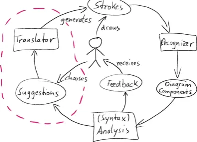
dle, drawsstrokes, which are the basic input of most sketch recognition tools. Therecognizer
transforms these strokes either on-line or on user’s request into a set of diagram components. Next, a language-specific analysisof the diagram is performed, e.g., a syntax check. For the diagram given in Fig.1, it might be checked that there are no arrows without proper source and target components or that processing components (rectangles) are connected to data structures (ellipses) only. The result of this analysis step is passed back to the user as visualfeedback.
The novel aspects of this work are surrounded
Figure 1: Proposed editor architecture by a dashed line. For the proposed approach, the
analysis additionally has to return aset of sug-gestionsfor the user, e.g., how the diagram can be completed. The user can choose among these suggestions, e.g., by using a preview of the cor-responding diagram changes. The selected sug-gestion then is integrated into the sketch. There-fore, a translator component generates the set of corresponding strokes and adds them to the user’s sketch. That way, the next analysis cycle will directly consider the applied suggestion.
This paper covers the following assistance fea-tures, which are all based onsyntax:
• auto-completion: the computation of missing diagram components that transform the in-complete diagram into a proper member of the underlying visual language,
• auto-link: the derivation of missing edges in graph-like languages according to node ar-rangement and other kinds of editing accelerators,
• example generation: the generation of correct example diagrams that can be explored by the user for the sake of language learning.
Suggestions that remove parts of a sketch are not considered.
Sketch tools with powerful recognizers [HD05,CMP05,CDR05] as well as tools for the com-putation or specification of suggestions [AHHG09,MMM08b,SBV08] already exist. Therefore, this paper focuses on the following three aspects:
• User interaction: how can the user invoke and control assistance,
• Stroke generation: how and where should the translator generate strokes from the sugges-tion (this actually is a graph drawing problem),
• Dealing with recognition errors: indeed, syntactical assistance not only provides clues for syntactical problems, but also simplifies the identification of recognition errors.
ECEASST
2
Business Process Models
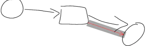
BPMs are used to represent the workflows within an enterprise and, thus, are a highly relevant di-agrammatic language today. In recent years a standardized visual notation, the Business Process Modeling Notation BPMN [Obj09], has been developed. Since BPMs are frequently developed in creative team meetings, this language ideally should be supported by sketch editors. Fig.2
shows a small sales process, which has been drawn and recognized by the sketching editor de-scribed in this paper. The magnified (assistance) toolbar will be dede-scribed later.
BPMs basically are graphs, where the connecting arrows represent sequence flow. The ex-ample process starts with the receipt of an order, which is expressed by a start event (circle). Thereafter, the sequence flow is split by an exclusive gateway (diamond shape). If the ordered product is available, it is prepared and shipped, which is expressed by activities (rectangles). Otherwise, a notification is sent to the customer. Thereafter, the sequence flow is joined again by another gateway, and the process terminates as indicated by the end event (circle).
In the following, only well-structured BPMs are treated, i.e., we require splits and joins to be properly nested. This restriction improves the understandability of process models in the same way as structured programming improves the understandability of program code [MRA09]. For well-structured BPMs, moreover, powerful syntactical user assistance is available [MM09].
3
The Frameworks
PerSUADE
and
DSketch
The general approach proposed in this paper (Fig.1) is generic as it is not restricted to a particular visual language. Hence, an implementation requires frameworks for sketch recognition as well as syntax analysis and user assistance that are generic as well, i.e., they must be adaptable to different visual languages. Concretely, we have chosen theDiaGenapproach [Min02] as a base, where hypergraphs are used as a model for diagrams and hypergraph grammars as a means for syntax definition. Accordingly, this formalism is introduced at first. Thereafter, thePerSUADE
approach, an extension ofDiaGenby syntax-based user assistance, is introduced. Finally, the sketching approachDSketch, which is also based onDiaGen, is recapitulated.
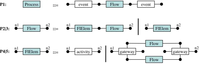
3.1 Hypergraphs and Hypergraph Grammars
Sketch-based Diagram Editors with User Assistance event event activity gate-way gate-way activity activity
Process ::= event Flow event
Flow ::= FlElem Flow
n1 n2 n1 n2
FlElem n1 n2 FlElem n1 n2 activity n1 n2 gateway n1 gateway n2 Flow Flow ::= P1: P2|3: P4|5:
Process event Flow event
gateway gateway
Flow
Flow
P1
P3
event FlElem eventP5
event event
2*(P3,P4)
gateway gateway activityactivity
event event
Figure 2: A sketched BPM fragment and its hypergraph representation
event event
activity
gateway gateway
activity activity
Process ::= event Flow event
Flow ::= FlElem Flow
n1 n2 n1 n2
FlElem n1 n2 FlElem n1 n2 activity n1 n2 gateway n1 gateway n2 Flow Flow ::= P1: P2|3: P4|5:
Figure 3: Hypergraph grammar for BPMs
In DiaGen, hypergraph grammars are used for language definition. For this paper, only context-free ones are considered [DHK97]. Such hypergraph grammars consist of two finite sets of terminal and nonterminal hyperedge labels and a starting hypergraph that contains only a single nonterminal hyperedge. Syntax is described by a set of productions. The hypergraph language generated by a grammar is defined by the set of terminally labeled hypergraphs that can be derived from the starting hypergraph.
Fig.3shows the productions of a hypergraph grammarGBPMfor very simple process models.
A more comprehensive version that includes pools (process containers), different kinds of inter-mediate events, and embedded messages has been shown in [MM09]. The typesevent,activity, andgatewayare the terminal hyperedge labels. The set of nonterminal labels consists ofProcess,
Flow, andFlElem. The starting hypergraph consists of just a single Processedge. The appli-cation of a context-free production removes an occurrenceeof the hyperedge on the left-hand side of the production from the host graph and replaces it by the hypergraphHron the right-hand side. Matching node labels of both sides of a production determine howHr has to fit in after removinge. Fig.4shows an example derivation.
3.2 User Assistance withPerSUADE
ECEASST
event event
activity
gateway gateway
activity activity
Process ::= event Flow event
Flow ::= FlElem Flow
n1 n2 n1 n2
FlElem n1 n2 FlElem n1 n2 activity n1 n2 gateway n1 gateway n2 Flow Flow ::= P1: P2|3: P4|5:
Process event Flow event
gateway gateway
Flow
Flow
P1
P3
event FlElem eventP5
event event
2*(P3,P4)
gateway gatewayactivity
activity
event event
Figure 4: Example derivation starting fromProcess
H:
merge nodes add edges
n4 n1
activity
event n2 n3 event n5
n3~n4 n1
activity
event n2 event n5 n1 event n2 activity n3 activity n4 event n5
Figure 5: Hypergraph patches by example
H into a valid member of the language defined by a given grammar G. Two different kinds of atomic modifications are considered: merging nodes and adding edges. The application of a patch for a hypergraphHthen corresponds to the construction of a so-called quotient hypergraph
H/∼whose nodes are equivalence classes of the original nodes ofH. Correcting patches indeed can be computed while parsing hypergraphs [MMM08a]. Consider the hypergraphH given in Fig.5 as an example. HypergraphH does not belong to the language ofGBPM, but it can be
corrected by merging the nodes n3 and n4. It can also be corrected by inserting an activity
hyperedge at the proper position. Note that there usually is an infinite number of correcting patches. Actually, according toGBPM, an arbitrary number of activities could be inserted between
theactivityand theeventhyperedge at the right. So, the size of desired patches, i.e., the number of additional hyperedges, must be restricted by the user. A special case of patches is the empty input hypergraph. Its patches can be used for exhaustive example generation.
Assistance based on hypergraph patches has been integrated intoDiaGeneditors as follows: The editor automatically maintains the hypergraph representation of the diagram. On user’s request, the patch-computing parser [MMM08a] is applied to this hypergraph representation with the desired size of patches as a parameter. It computes all possible correcting hypergraph patches of this size. From those, the user has to choose via a preview functionality. The selected patch is translated to diagram modifications by a language-specificupdate translator. Finally, the diagram is beautified by alayoutcomponent. That way, powerful syntax-based user assistance for BPMs has been realized already [MM09] – however, only in the context of a conventional WIMP editor. A screencast is available atwww.unibw.de/inf2/DiaGen/assistance/bpm.
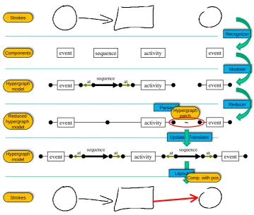
Sketch-based Diagram Editors with User Assistance Editor Specification Hypergraph model Modeler Reduced hypergraph model Reducer Diagram Components Drawing tool Editor user uses Semantic represen- tation Attribute evaluation
Parser Derivation structure Strokes Recognizer highlights correct diagram generates event activity sequence activity event event sequence at at at activity event sequence at event sequence event Process event Flow event
ship order
BPEL:
<invoke name="ship order"/>
FlElem activity
Figure 6: Architecture ofDSketch(figure based on [BM08c])
3.3 Diagram Recognition `a laDSketch
DSketchis an extension ofDiaGenthat complements the conventional WIMP-based GUI of di-agram editors by a drawing canvas, which readily accepts all kinds of user strokes freely entered with a stylus. The integrated recognizer allows diagrams to be analyzed and further processed [BM08c]. The main characteristics of this approach are: (i) Little restrictions to drawing compo-nents, e.g., a rectangle can be drawn clockwise, counterclockwise, or even interleaved with other components. (ii) Syntactic and semantic information is used to resolve ambiguities that occur in the recognition process. For instance, if a sloppily drawn BPM component could be both an activity or an event, the actual decision is postponed to the analysis stage where the interpreta-tion of the respective strokes might get clear from the context. And finally (iii), the approach is generic, i.e., editors for a wide range of languages can be specified.
ECEASST
Analysis Assistance
Strokes /
Text Recognizer
Modeler
Reducer
Conv. parser
Components
Hypergraph patches Update
Translator Layout
Stroke Generator
Reduced hypergraph
model Components
with positions
Hypergraph model
Feedback
gets preview
accepts
chooses creates
receives
PerSUADE
Hypergraph model
Figure 7: Novel architecture of sketch editors
derivation is computed via attribute evaluation. If this is not possible, the next best derivation is tried and so on. Details about this process can be found in [BM08a].
The DSketchapproach is efficient and fully functional, but it cannot recognize dashed lines nor distinguish different line widths. BPM messages, which are usually drawn as dashed lines, and BPM end events, which are drawn as bold circles, thus, must be represented with another notation. Moreover, text recognition is not integrated intoDSketch. Textual labels, hence, must be entered via keyboard or an extra text recognizer.
4
Integration of User Assistance into
DSketch
In this section we describe how the assistance provided byPerSUADEhas been integrated into
DSketch. The overall architecture of the editors generated by the realized system is shown in Fig.7, which basically refines Fig.1. The right-hand side of Fig.7comprises the analysis steps ofDSketch. The analysis performed by the PerSUADE parser belongs to this side, too. The left-hand side comprises the novel part of the system where the results ofPerSUADEare further processed for the sake of assistance.
Sketch-based Diagram Editors with User Assistance
Update Translator
Reducer Modeler Recognizer
at at
activity event
sequence
event
activity
event ~ event
at at
activity event
sequence
event
at at sequence
event sequence activity event
Parser
Hypergraph patch Strokes
Components
Hypergraph model
Reduced hypergraph
model
Strokes
Layout
Comp. with pos. Hypergraph
model
Figure 8: Processing steps by example
The next adapted component is the parser, i.e., the process of syntactically analyzing the dia-gram. Actually, theDSketchparser has remained unchanged, but an additional parser component from thePerSUADEframework now complements it. All kinds of assistance are supported by this parser instead of the normalDSketchparser. On user’s request, this parser computes hyper-graph patches for (the recognized parts of) the diagram’s reduced hyperhyper-graph model. The user can explore these patches and choose one of them using a preview functionality.
ECEASST
Figure 9: Auto-completion examples. Suggested completions are drawn in red.
Figure 10: Example generation
4.1 Placement of New Components by the Use of Graph Drawing Techniques
A basic assumption of our implementation is that user strokes remain unchanged (in contrast to conventionalPerSUADE editors, where the existing components can be adapted during as-sistance). That way, surprises are prevented and the special flavor of sketching is preserved. So, we need a flexible layout engine for graph-like languages (other languages would require some adaptations) that only integrates the new components and leaves the remaining diagram unchanged. These requirements can be satisfied by layout algorithms based on physical analo-gies [Bra01]. Concretely, we have adapted a spring embedder, which interprets edges as springs with their particular attraction forces. Furthermore, special repulsive forces take effect between the node components. During layout, the node components move in increments according to the respective sum of forces until an equilibrium state has been reached. However, in our con-text not all nodes can be moved around freely, but only the new ones introduced by the update translator. The existing nodes, in contrast, are locked into their positions. An important benefit of spring embedders besides their simplicity is that they can also be used for static layout in a straightforward way. Static layout is required here, e.g., for example generation (cf. Fig.10).
There are two problems with spring embedders in our context: The top diagram of Fig. 9
would look much better if the new activity were positioned further to the top. However, spring forces pull the new activity to the presented position, i.e., springs prevent bent arcs that way. This behavior can only be avoided by introducing invisible components in a context-sensitive way. Another problem is that new components, if positioned randomly at the beginning, cannot “pass” existing components due to the repulsive forces. This may result in strange layouts. We have prevented this problem by introducing an additional processing step that guesses more appropriate initial coordinates for new node components to be refined afterwards.
Sketch-based Diagram Editors with User Assistance
algorithms are less suited in the context of this paper where the (usually user-chosen) position of existing nodes must be preserved when new nodes or edges have been introduced.
4.2 User Interface
The actual user interface is quite simple and easy to use — the complete editor window is shown in Fig. 2. There is a button for starting the computation of patches (see the magnified part of Fig. 2). After pressing this button, the first solution is shown immediately. Arrow buttons can be used for browsing through the other solutions. In particular the generation of examples usually results in a large number of solutions. A check button has to be pressed in order to accept the currently previewed solution. Strokes are then generated from the previewed diagram components. The resulting diagram looks like the preview, but the new components are not highlighted anymore, but drawn as normal, although perfect, strokes. Note that the user does not need to accept the previewed solution, but can use it as a kind of template for drawing the suggested components with his own strokes. That way, he will get a diagram that looks more homogeneous than the one with the generated perfect strokes. To continue with the UI, the preview also can be canceled, of course. Finally, the patch size can be set via the plus and minus buttons. This parameter basically indicates how many new diagram components (or more precisely, terminal hyperedges) are to be introduced. In the figure this parameter is set to its default value 1.
5
Discussion
Although an elaborate user study still remains to be done, the results so far are promising. As before, the user can freely sketch diagrams. He is not restricted in any way in the creative process of sketching. This actually is the reason why we have not realized a more pervasive assistance, e.g., on-line after every single stroke. In many conventional sketch editors, the user is in trouble if his sketch cannot be recognized. With the developed editor, he can ask for syntactical guidance instead. But this is not the only help he can get as we describe next.
5.1 Location of Recognition Errors
An important benefit of our approach is that it helps identifyingrecognition errors(besides syn-tax errors). Consider Fig.11as an example. A human can easily see that the sketched diagram is a structured business process. Still the diagram is not correctly recognized byDSketch. Nor-mally, the user would have no clue what is wrong here. Has the start event mistakenly been recognized as an activity? Or has the end event been drawn too sloppily? Invoking assistance yields the answer. The red arrow between the activity and the end event clearly points out the problem: either the existing arrow has not been correctly recognized, or the gap between its head and the end event is too large. In either case, the user now can correct this problem without the need to redraw the whole diagram. It would even be possible to automatically mask or remove those strokes that do not contribute to the solution.
ECEASST
Figure 11: Identification of recognition errors
of the whole BPM. It simply is not well-structured anymore as we have required by the grammar. With a more relaxed syntax definition at least sub-diagrams would be recognized correctly so that the visual feedback given by theDiaGen parser might indicate what is wrong. Actually, languages, where either the whole diagram or nothing is recognized as correct, have been very critical for sketching systems so far, because the recognition rate exponentially drops down with the size of the diagram. This problem is solved with our approach (although it would be even better to re-feed the analysis result in the recognizer, so that it can try harder at the weak points).
5.2 Stroke Interference
A problem of integratingPerSUADEinto a sketching system is that it may happen that a sketch is not recognized as correct after a suggested patch has been accepted by the user. When using
PerSUADE in conventional WIMP editors, this cannot happen: diagrams resulting from the application of assistance are always correct. In the context of sketching, newly generated strokes may interfere with existing strokes that, e.g., had been ignored by stroke recognition before.
6
Related Work
Of course, there are also other sketch editors for BPMs such as [MS09]. Moreover, due to the practical relevance of this language, various kinds of guidance have been developed for con-ventional WIMP-based BPM environments (an example is [BBM+09]). However, to our best knowledge such guidance has not been integrated into sketch editors yet.
Sketch-based Diagram Editors with User Assistance
Another meta-tool where it should be possible to combine assistance with sketching is the Marama toolkit. For Marama, both a critic authoring tool [AHHG09] for the specification of user feedback and a sketching framework [GH07] are available. Here, however, critics would have to be specified manually whereas we gain the feedback automatically from the parser. The strong points of [GH07] are that only very little extra specification effort is needed for complementing a normal diagram editor with a sketching editor and that the user can easily overrule the recognizer when it makes a mistake.
7
Conclusion
In this paper we have shown that user assistance functionality can be provided by sketch editors and that this actually is useful. The presented approach allows to generate sketching editors with user assistance from a language specification based on the existing sketching editor generator
DSketchand the user assistance libraryPerSUADE. As a representative example, we have created a sketch editor for business process models with assistance features such as auto-completion or example generation.
But we have noticed yet another benefit of this approach besides helping the user with the language. The very same assistance features actually can be put to a good use in locating recog-nition errors. Those often directly result in syntax errors, whose potential corrections then point the user precisely to the recognition error. If a new component is suggested as a correction where already a component exists, the user can conclude that the existing component had been drawn too sloppily and needs to be redrawn.
The developed sketch editor for business process models is demonstrated in several screencasts and can be downloaded fromwww.unibw.de/inf2/DiaGen/assistance/sketching.
Future Work
In the future we want to experiment with relaxations of the assumption that the existing user strokes must not be changed. It is certainly imaginable that sketched components are moved around or even resized similar to the assistance in conventional DiaGeneditors [MM09]. In this context it should also be possible to integrate existing component fragments into the newly introduced components in order to reuse as many strokes of the user as possible.
It would be also important to integrate the suggestions into the diagram closely following the user’s drawing style. Perfect components mixed with sloppily drawn components make the diagram look inhomogeneous. Costagliola et al. have proposed a stroke repository to this end, which is used already for their symbol completion [CDR07]. Alternatively, the user strokes could be beautified to close this gap.
ECEASST
Bibliography
[AHHG09] N. M. Ali, J. Hosking, J. Huh, J. Grundy. Critic Authoring Templates for Specifying Domain-Specific Visual Language Tool Critics. InProc. 2009 Australian Software Engineering Conf.Pp. 81–90. IEEE, 2009.
[BBM+09] M. Born, C. Brelage, I. Markovic, D. Pfeiffer, I. Weber. Auto-completion for Ex-ecutable Business Process Models. InBusiness Process Management Workshops. LNBIP 17, pp. 510–515. Springer, 2009.
[BM08a] F. Brieler, M. Minas. Ambiguity Resolution for Sketched Diagrams by Syntax
Analysis Based on Graph Grammars. In Proc. Seventh Int. Workshop on Graph
Transformation and Visual Modeling Techniques. Electronic Communications of the EASST 10. EASST, 2008.
[BM08b] F. Brieler, M. Minas. A Model-Based Recognition Engine for Sketched Diagrams.
InProc. VL/HCC Workshop on Sketch Tools for Diagramming. Pp. 19–28. 2008.
[BM08c] F. Brieler, M. Minas. Recognition and processing of hand-drawn diagrams using
syntactic and semantic analysis. InProc. Working Conf. on Advanced Visual Inter-faces. Pp. 181–188. ACM, 2008.
[Bra01] U. Brandes. Drawing on Physical Analogies. In Drawing Graphs: Methods and
Models. LNCS 2025, pp. 71–86. Springer, 2001.
[CDR05] G. Costagliola, V. Deufemia, M. Risi. Sketch Grammars: A Formalism for
Describ-ing and RecognizDescrib-ing Diagrammatic Sketch Languages. InProc. Eighth Int. Conf. on Document Analysis and Recognition. Pp. 1226–1231. IEEE, 2005.
[CDR07] G. Costagliola, V. Deufemia, M. Risi. Using Grammar-Based Recognizers for
Sym-bol Completion in Diagrammatic Sketches. InProc. Ninth Int. Conf. on Document Analysis and Recognition. Pp. 1078–1082. IEEE, 2007.
[CDR08] G. Costagliola, V. Deufemia, M. Risi. Using Error Recovery Techniques to Improve Sketch Recognition Accuracy. InProc. 7th Int. Workshop on Graphics Recognition. LNCS 5046, pp. 157–168. Springer, 2008.
[CMP05] R. Chung, P. Mirica, B. Plimmer. InkKit: A generic design tool for the tablet PC. InProc. 6th ACM SIGCHI NZ chapter’s Int. Conf. on Comp.-Human Interaction. Pp. 29–30. ACM, 2005.
[DHK97] F. Drewes, A. Habel, H.-J. Kreowski. Hyperedge Replacement Graph Grammars.
InHandbook of Graph Grammars and Computing by Graph Transformation. Vol. I: Foundations. Pp. 95–162. World Scientific, 1997.
[GH07] J. Grundy, J. Hosking. Supporting Generic Sketching-Based Input of Diagrams in a
Sketch-based Diagram Editors with User Assistance
[HD05] T. Hammond, R. Davis. LADDER, a sketching language for user interface
devel-opers.Computers & Graphics29(4):518–532, 2005.
[Min02] M. Minas. Concepts and Realization of a Diagram Editor Generator Based on
Hypergraph Transformation. Science of Computer Programming 44(2):157–180,
2002.
[MM09] S. Mazanek, M. Minas. Business Process Models as a Showcase for Syntax-based
Assistance in Diagram Editors. InProc. 12th Int. Conf. on Model Driven Eng. Lang. and Sys.LNCS 5795, pp. 322–336. Springer, 2009.
[MMM08a] S. Mazanek, S. Maier, M. Minas. An Algorithm for Hypergraph Completion
Ac-cording to Hyperedge Replacement Grammars. In Proc. 4th Int. Conf. on Graph
Transformations. LNCS 5214, pp. 39–53. Springer, 2008.
[MMM08b] S. Mazanek, S. Maier, M. Minas. Auto-completion for Diagram Editors based on
Graph Grammars. In 2008 IEEE Symposium on Visual Languages and
Human-Centric Comp.Pp. 242–245. IEEE, 2008.
[MRA09] J. Mendling, H. Reijers, W. van der Aalst. Seven Process Modeling Guidelines
(7PMG).Information and Software Technology, 2009.
[MS09] N. Mangano, N. Sukaviriya. Liberating Expression: A Freehand Approach to
Busi-ness Process Modeling. InProc. 12th IFIP TC 13 Int. Conf. on Human-Comp. In-teraction. LNCS 5727, pp. 834–835. Springer, 2009.
[Obj09] Object Management Group. Business Process Modeling Notation (BPMN). 2009.
http://www.omg.org/docs/formal/09-01-03.pdf.
[SBV08] S. Sen, B. Baudry, H. Vangheluwe. Domain-Specific Model Editors with Model

![Figure 6: Architecture of DSketch (figure based on [BM08c])](https://thumb-us.123doks.com/thumbv2/123dok_us/7810329.2085925/7.595.136.465.149.337/figure-architecture-dsketch-gure-based-bm-c.webp)