EVault Software
System Restore 1.1
User Guide
Contents
1 OVERVIEW...6
2 SYSTEM REQUIREMENTS...7
2.1 Minimum Hardware Requirements ... 7
2.1.1 Other Hardware...7
2.2 Supported Operating Systems... 7
2.3 Supported File Systems... 7
2.4 Supported Storage Types... 7
3 CREATING A BARE METAL RESTORE (BMR) STYLE BACKUP...8
4 CREATING BOOTABLE MEDIA FOR ESR...8
4.1 Running the Application ... 9
4.2 System Restore - Main Menu...11
5 CONFIGURING SETTINGS...13
5.1 Network Settings...14
5.1.1 Network Configuration...15
5.1.1.1 Static IP Configuration... 16
5.1.1.2 DHCP Configuration... 16
5.2 Disk Settings...17
5.3 All Devices Settings ...18
5.4 Log Settings...19
5.5 Driver Installation ...21
6 RESTORE MY SYSTEM...22
6.1 Restore Wizard...22
6.1.1 Step 1: Select Source...24
6.1.2 Step 2: Select a Restore Point...26
6.1.3 Step 3: Create Restore Plan...30
6.1.3.1 Basic volumes and Dynamic volumes... 35
6.1.3.2 Recovering a Dynamic disk to a Basic disk... 36
6.1.4 Step 4: Execute Plan...37
7 REPAIR MY SYSTEM...40
7.1 HAL and Kernel Repair ...41
7.2 Boot Critical Devices Repair ...42
8 RESTORE TEST-RUN...44
9 APPENDIX...45
9.1 Enabling Network Boots...45
9.1.1 Remote Server Setup...45
9.1.2 Client Setup...46
9.3 Restoring Applications such as SQL Server and Oracle...46
9.4 Creating BMR-Style Backups Using EVault Software...48
9.4.1 Steps for Creating a BMR-Style Backup Job...48
9.4.1.1 Running Your Job... 52
9.4.2 Creating BMR Inclusions and Exclusions...52
9.4.3 Upgrading an Existing Job to BMR Style...54
10 GLOSSARY...55
Table of Figures
Figure 1.- Welcome Screen...9
Figure 2.- License Agreement...10
Figure 3.- Main Menu...11
Figure 4.- Settings Screen...13
Figure 5.- Network Settings...14
Figure 6.- Network Configuration...15
Figure 7.- Disk Settings...17
Figure 8.- All Devices Settings...18
Figure 9.- Log Settings...19
Figure 10.- Driver Installation...21
Figure 11.- Restore Wizard...23
Figure 12.- Select Source Type...24
Figure 13.- Choose Backup Location...25
Figure 14.- Select a Protected System to Restore...27
Figure 15.- Select Backup Job...28
Figure 16.- Select Restore Point...29
Figure 17.- Map Restore Volumes...31
Figure 19.- Confirm Restore Plan...34
Figure 20.- Example of Dynamic Volumes...35
Figure 21.- Example of Mapping Dynamic Volumes...36
Figure 22.- Execute the Restore Plan...37
Figure 23.- Restore Complete...38
Figure 24.- Repair Wizard...40
Figure 25.- Restore Test-Run Wizard...44
Figure 26.- Create a New Job...48
Figure 27.- Choose Local System...49
Figure 28.- Select Bare Metal Restore...49
Figure 29.- Optional: Specify Encryption and Advanced Options...50
Figure 30.- Optional: Create a Schedule...50
Figure 31.- Specify a Vault...51
Figure 32.- Run Your Job...51
Figure 33.- Including Specific Data...52
Figure 34.- Excluding a File or Directory...53
Revision: This manual is for version 1.1. Software Version: 1.10 (March 2010) 1997-2010 i365 Inc.
i365, A Seagate Company, makes no representations or warranties with respect to the contents hereof and specifically disclaims any implied warranties of merchantability or fitness for any particular purpose. Furthermore, i365 reserves the right to revise this publication and to make changes from time to time in the content hereof without obligation of i365 to notify any person of such revision of changes. All companies, names and data used in examples herein are fictitious unless otherwise noted.
No part of this document may be reproduced, transmitted, transcribed, stored in a retrieval System or
translated into any language including computer language, in any form or by any means electronic, mechanic, magnetic, optical, chemical or otherwise without prior written permission of:
i365, A Seagate Company c/o Corporation Trust Center 1209 Orange Street
Wilmington, New Castle Delaware 19801 www.i365.com
EVault, EVault Software, EVault SaaS, and EVault DeltaPro, are registered trademarks of i365, A Seagate Company. All other products or company names mentioned in this document are trademarks or registered trademarks of their respective owners.
Acknowledgements: Two encryption methods, DES and TripleDES, include cryptographic software written by Eric Young. The Windows versions of these algorithms also include software written by Tim Hudson. Bruce Schneier designed Blowfish encryption.
“Part of the software embedded in this product is gSOAP software. Portions created by gSOAP are Copyright 2001-2006 Robert A. van Engelen, Genivia Inc. All Rights Reserved. THE SOFTWARE IN THIS PRODUCT WAS IN PART PROVIDED BY GENIVIA INC AND ANY EXPRESS OR IMPLIED WARRANTIES,
INCLUDING, BUT NOT LIMITED TO, THE IMPLIED WARRANTIES OF MERCHANTABILITY AND FITNESS FOR A PARTICULAR PURPOSE ARE DISCLAIMED. IN NO EVENT SHALL THE AUTHOR BE LIABLE FOR ANY DIRECT, INDIRECT, INCIDENTAL, SPECIAL, EXEMPLARY, OR CONSEQUENTIAL DAMAGES (INCLUDING, BUT NOT LIMITED TO, PROCUREMENT OF SUBSTITUTE GOODS OR SERVICES; LOSS OF USE, DATA, OR PROFITS; OR BUSINESS INTERRUPTION) HOWEVER CAUSED AND ON ANY THEORY OF LIABILITY, WHETHER IN CONTRACT, STRICT LIABILITY, OR TORT (INCLUDING
NEGLIGENCE OR OTHERWISE) ARISING IN ANY WAY OUT OF THE USE OF THIS SOFTWARE, EVEN IF ADVISED OF THE POSSIBILITY OF SUCH DAMAGE.”
The EVault Software Agent, EVault Software CentralControl, and EVault Software Director applications provide encryption options for 128/256-bit AES (Advanced Encryption Standard). Advanced Encryption Standard algorithm (named Rijndael, pronounced “Rain Doll”) was developed by cryptographers Dr. Joan Daemen and Dr. Vincent Rijmen. This algorithm has been chosen by the National Institute of Standards and Technology (NIST) of the U.S. Department of Commerce to be the Federal Information Processing Standard (FIPS).
The EVault Software Agent and EVault Software Director applications include the security feature of over-the-wire (OTW) encryption.
1 Overview
The EVault System Restore (ESR) application is a disaster recovery solution for
Windows-based computers. This solution allows you to completely restore your machine from a bare metal state in the event of a disaster, without having to re-install the
operating system, or perform any hardware configurations.
ESR provides fast, easy to use system restores. It also provides full bare-metal restores to dissimilar hardware, and even virtual machines.
Protected System: This is the source system, which needs to be protected from catastrophic failures. On this system, a backup application must be installed, and backups created.
Target System: This is the receiving system, which may be in a “bare metal” state, or which may contain existing information that will be lost (overwritten) on a restore. You need to run ESR in this target system. It will restore the backed up image, and then the system can be started (rebooted).
Note: In some cases, you may not be able to restore if the target hardware is
incompatible with the source OS. For example, a 64-bit OS will not restore if the target machine hardware is not compatible with a 64-bit OS, or drivers for the 64-bit OS do not exist. Some non-Intel or non-AMD processors, such as Itanium, may not restore to Intel/AMD processors.
This product addresses the need for a short recovery time objective (RTO), while avoiding a manual bare metal recovery process, which can be time consuming and error prone. ESR can restore your entire system, including the operating system,
applications, System State, and data. In minutes, you can restore from backups created using EVault Software.
EVault System Restore enables you to:
• Restore your server to similar, dissimilar or virtual environments
• Restore your system to a selected point in time
• Restore from image or file-based backups
• Restore from local backups or backups stored on the Vault
• Choose your boot media. You can boot from CD, DVD, USB, or a network.
Note: ESR 1.10 no longer supports EVault Real Time Protection (ERTP). But the previous versions of ESR 1.03 and below continue to support ERTP.
Audience: This User Guide is intended for IT administrators who are responsible for performing backup and recovery operations, and have a good understanding of computer fundamentals.
2 System
Requirements
2.1 Minimum Hardware Requirements
EVault System Restore requires the following (minimum) hardware:
• Pentium processor or higher
• 700 MB RAM
• CD/DVD drive
2.1.1 Other Hardware
• Network Interface Card (optional, for network booting)
2.2 Supported Operating Systems
See the release notes for more information.
• Windows XP (32 bit)
• Windows SBS (32 bit)
• Windows 2003 (32/64 bit)
• Windows 2008 (32/64 bit)
• Windows Vista (32/64 bit)
Note: Hyper-V is a hypervisor-based virtualization system for 64-bit systems. ESR can back up a Hyper-V machine with multiple running partitions. After you restore to a new machine, you can access the newly restored VMs as you did before the backup.
2.3 Supported File Systems
• NTFS
2.4 Supported Storage Types
• Vault
• SAN
• USB Drives
• NAS
3
Creating a Bare Metal Restore (BMR) Style Backup
EVault System Restore is a Bare Metal Restore technology that leverages backups created by EVault Software/SaaS. In order for you to restore your system, you must have previously created backup images using one of the two backup applications. Section 9.4 provides an overview of how to create a BMR-style backup. For detailed instructions for creating backups using EVault Software, refer to the EVault Agent User Guide.4
Creating Bootable Media for ESR
EVault System Restore is bundled as a bootable image. You need to boot the target system using the ESR ISO image to be able to run the restore application. The types of bootable media that you can use are:
• CD/DVD – Burning the ISO image to a CD will yield a bootable ESR disk.
• USB – A bootable USB device with the ESR application can be created by applying the WIM or ISO image to a USB device.
• Network Boot – The WIM or ISO image may also be used to set up a PXE boot
server.
To launch ESR using a CD/DVD:
1) Insert the ESR CD/DVD that you have burned into the drive of the machine you want to restore.
2) Power on the system to auto-launch the ESR application.
Note: Make sure that the CD/DVD device is the first option in the boot order of the BIOS. If you have another bootable device that is listed prior to the
CD/DVD drive, ESR may not launch automatically. To launch ESR using USB Boot:
1) Plug your USB device into the port on the system to auto-launch the ESR application.
2) Restart the computer.
Note: Make sure that the USB is the first option in the boot order of the BIOS. The BIOS must have built-in support for booting USB devices. If you have another bootable device that is listed prior to the USB drive, ESR may not launch automatically.
To launch ESR using Network Boot:
1) Reboot the system that is being restored from the PXE boot ROM.
Note: Make sure the PXE option is enabled in BIOS. It is the User’s responsibility to take the WIM image and create a PXE server to enable network boot functionality. You must also provision the necessary hardware and software to enable the PXE server.
2) Press F12 to start the network service boot wizard when prompted. F12 may not work on all systems. Follow the instructions on the screen.
Note: Before launching the application from the network, make sure that the DHCP server is set up in the network where the system being restored resides.
Note: A network card must be present in the system when the backup is taken and connected (by a network) to one in the remote server.
Refer to the appropriate Microsoft documentation describing how to enable PXE boot servers.
4.1 Running the Application
When you launch the application, the Welcome Screen appears.
1) Choose your time zone from the dropdown list. The restore points on backups are stored in UTC, so when these restore points display in the restore point selection screen, they are translated to the selected (local) time zone.
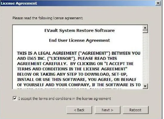
2) Click OK to proceed. The License Agreement screen will appear.
Figure 2.- License Agreement
3) Read the license agreement for the EVault System Restore software. 4) Select the I accept... checkbox.
or
Click Reboot if you do not wish to accept the terms/conditions specified in the license agreement. This will reboot the system, allowing you to exit properly from the ESR application.
4.2 System Restore - Main Menu
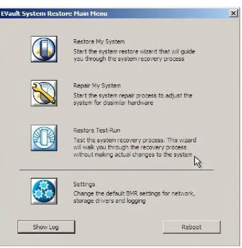
Figure 3.- Main Menu
The Main Menu screen has two sections. The three upper options let you perform restores and repair tasks. The lower options let you configure settings, view logs, and reboot the system.
Restore/Repair Options
Restore My System: Allows you to initiate the process of restoring your system from its bare metal state.
Repair My System: Allows you to repair your system by adjusting for dissimilar hardware configurations. Typically, you would use Restore My System first, to copy the system volume and possibly other volumes to local disks. Then, if needed, you would be directed to run a repair. Optionally, if the system does not need to be restored (again), you can go straight to the Repair Wizard.
Restore Test-Run: Allows you to test the system recovery process without making actual changes to the system. It demonstrates that you can restore the system when necessary.
Additional Options
Settings: Allows you to configure settings for network devices, storage devices and logs on your system if they are not already correctly configured.
Show Log: Allows you to view or save logs during the restore process.
Reboot:Allows you to exit the ESR application. You can then return to the restored system.
5 Configuring
Settings
You may need to configure your settings before you start restoring or repairing your system. The network settings allow you to configure the network devices of the system that you are restoring to if they are not already automatically configured correctly. Network connectivity is required for restoring from backups stored on a NAS, SAN or Vault.
You may configure the disk settings to add disk drivers to use disks for the restore process that are not automatically recognized and configured. It is possible to choose to configure your settings during the restore or repair process.
To configure the settings, click the Settings icon from the Main Menu. The Settings screen will appear:
5.1 Network
Settings
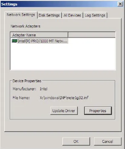
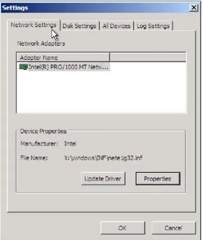
The Network Settings tab displays all network adapters that are connected to the system. The Device Properties section provides the information about the driver for the selected network adapter. The Properties button allows you to configure the IP address, Gateway and DNS details. The Update Driver button allows you to install a driver in case the driver for the selected network adapter is not available.
If you do not configure the network settings before you start the restore or repair process, network connectivity may not be available, and you won’t be able to restore your system over the network.
To configure the network settings:
1) On the Settings screen, select the Network Settings tab.
Figure 5.- Network Settings
3) Click Install to install the driver required for the selected network adapter if the required driver is not already available.
or
Click Update Driver if the driver is already available, but requires updating. Note: If there are no drivers for the device, the Install button will display. If there is a driver (but perhaps the wrong one), the Update Driver button will display.
4) Click Properties to configure the IP address, DNS, and Gateway for the selected network adapter if the required driver is already available.
5) Click OK to apply the settings.
5.1.1 Network Configuration
Network Configuration lets you set the IP address, Gateway and other DNS details for the selected network adapter. This option is available only if the network adapters are configured appropriately with the drivers, a LAN is connected, and the port is enabled. To open the Network Configuration screen, go to:
Main MenuÆSettingsÆNetwork SettingsÆProperties
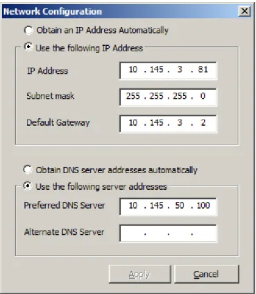
Figure 6.- Network Configuration
By default, an IP address will be automatically assigned using DHCP. If you do not have DHCP, or you wish to assign a specific IP address, you will need to set a static IP address.
5.1.1.1 Static IP Configuration
To set a static IP address for the selected network adapter:
1) In the Network Configuration screen, click Use the following IP Address. 2) Enter the required IP address, subnet mask, and default gateway for the network
adapter in the respective fields.
3) Click Use the following server addresses.
4) In the Preferred DNS Server field, enter the primary DNS IP address for the network adapter. You may also provide an IP address for an alternate DNS server.
5) Click Apply to apply the specified IP address to the network adapter.
Note: DNS server details are optional. They are required only for accessing other systems through computer domain names instead of IP addresses.
5.1.1.2 DHCP Configuration
To set the dynamic IP address for the selected network adapter:
1) In the Network Configuration screen, click Obtain an IP Address Automatically. 2) Click Obtain DNS server addresses automatically.
5.2 Disk
Settings
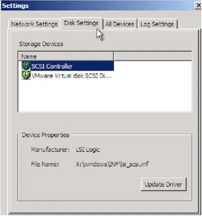
The Disk Settings tab lists all of the storage devices that are connected to the system.
Figure 7.- Disk Settings To configure the disk settings:
1) On the Settings screen, click the Disk Settings tab. 2) Select the required storage device.
3) Click Install to install the driver required for the selected storage device if the required driver is not available.
or
Click Update Driver if the required driver is already available, but you wish to replace it.
Note: If there are no drivers for the device, the Install button will display. If there is a driver (but perhaps the wrong one), the Update Driver button will display.
Installing Disk Drivers
5.3 All Devices Settings
The All Devices tab lists devices that are not listed in the Network or Disk Settings tabs. Depending on your specific hardware configuration, you may need to install the required drivers for selected PCI devices. You can do so through this tab.
Figure 8.- All Devices Settings To configure the All Devices settings:
1) On the Settings screen, click the All Devices tab. 2) Select a device.
3) Click Install to install the driver required for the selected storage device if no driver is available.
or
Click Update Driver if a driver is already available.
Note: If the storage devices do not have drivers already installed, the Install button will display. Otherwise, the Update Driver button will display.
4) Click OK to apply the settings. Installing All Devices Drivers
5.4 Log
Settings
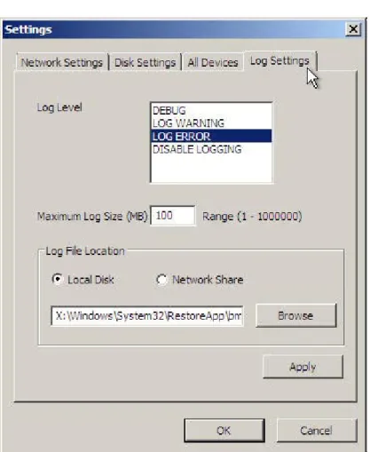
You can choose to create a log file for each restore Job. This file can include error messages, failure messages, and warnings encountered during a restore process. The Log Settings tab allows you to configure the following details for your log file.
• Log Level: The available levels follow.
a) DEBUG: Records all of the log messages
b) LOG WARNING: Logs only warnings and error messages c) LOG ERROR: Logs only errors
d) DISABLE LOGGING: No log is generated
• Maximum Log Size: You can restrict the log size to conserve disk space. Otherwise, the log size is set to the default. The maximum log file size is set initially to 100 MB. It is recommended that detailed logs be placed on a separate device because the default X: drive is a RAM drive, which is lost after reboots.
• Log File Location section: This specifies where to save the log file.
Note: You can configure the log settings only from the Settings icon from the Main Menu screen.
To configure log settings:
1) On the Settings screen, choose Log Settings. 2) Select a level from the Log Level box.
3) Use the Maximum Log Size field if you want to restrict the size of the log file. If you specify a maximum size, once that maximum is reached, the log will wrap around and overwrite the file from the beginning.
4) For the Log File Location:
Choose Local Disk if you want to save the log file on a local disk. or
Choose Network Share if you want to save the log file on the network. 5) Enter the full address for the log file location.
5.5 Driver
Installation
The EVault System Restore CD comes preloaded with commonly used recovery-critical drivers.
You may need to restore critical drivers if the hardware you are restoring to (and running ESR on) includes hardware that is not recognized by ESR.
In this circumstance, you will need to manually install the required driver as follows. When you click Update on the Network Settings tab, the Install Driver screen appears.
Figure 10.- Driver Installation
To install a driver for the selected network adapter:
1) Choose Local Disk to install the driver from a local disk. or
Choose Network Share to install the driver from a network share.
2) If you select Local Disk, you can use the Browse button, or enter the path name manually. If you select Network Share, the Browse button is disabled, and you must enter the full path name for the location of the driver.
6
Restore My System
EVault System Restore allows you to restore your system after a crash. You can restore to a different system and adjust for differential hardware.
Note: In some cases you may not be able to restore if the target hardware is
incompatible with the source OS. For example, a 64-bit OS will not restore if the target machine hardware is not compatible with a 64-bit OS, or drivers for the 64-bit OS do not exist. Some non-Intel or non-AMD processors, such as Itanium, may not restore to Intel/AMD processors.
But if the machine you are restoring to does support your version of the OS, you should be able to restore (even, for example, if the disks are different).
Use the Restore My System option from the Main Menu to go through the steps to restore the system to its previous, usable state or to any point in time for which you have a backup.
6.1 Restore
Wizard
Using the Restore Wizard, you can recover your system to:
• Similar hardware • Dissimilar hardware • Virtual hardware
To initiate the process of restoring, click Restore My System on the Main Menu. (Figure 3 illustrates the Main Menu.)
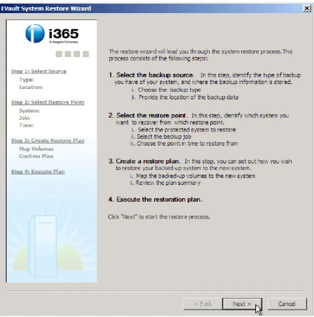
Figure 11.- Restore Wizard
The EVault System Restore Wizard screen has two panels.
Left Panel: The left side of the Restore Wizard displays a quick view of the current stage in the restore process.
A gray area denotes a step that has not run yet.
A black area denotes the current step you are working on. A green area denotes a step that has finished.
Right Panel: The right side of the Restore Wizard describes the steps of the restore process.
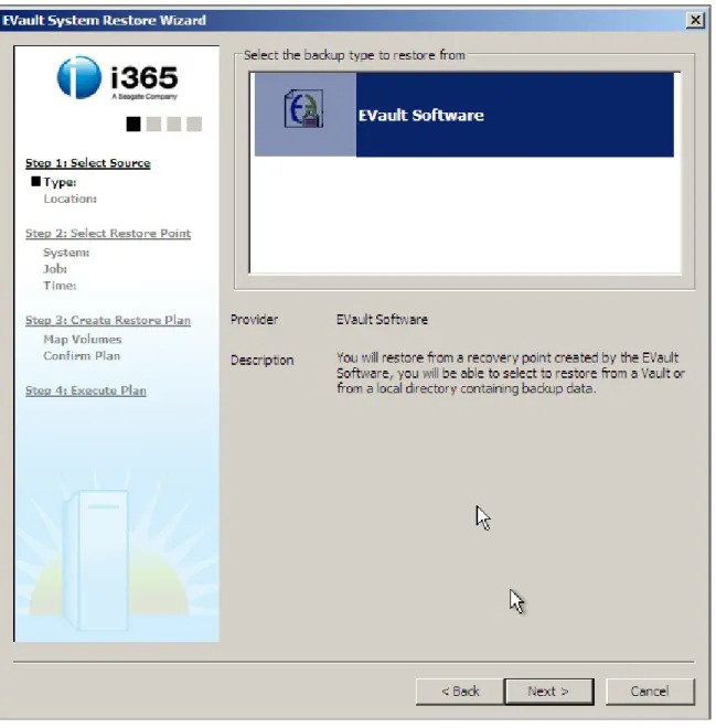
6.1.1 Step 1: Select Source
The first step in the System Restore process is Select Source.
This step allows you to choose the backup type that was used to create your system backup, and the location where the backup is stored. You can restore your system from backups located on directly attached storage, network-attached storage, or a Vault, depending on your backup type.
See section 9.4 for more information about backup types.
To perform Step 1: Select Source
1) Select the required backup source type:
Note: EVault Software backup service supports restoring from a local backup, or a remote Vault on the network.
2) Click Next to continue.
The backup locations available are:
Local Disk: Choose Local Disk if the location of the backup image and the system that is restored are on the same locally attached device, such as a USB drive. Network Share: Choose Network Share (i.e., \\server\path\) if the location of the backup image is different from that of the system that is restored and is connected within the network.
Vault: Choose Vault if the location of the backup image is a Vault. (Only enabled if you have chosen EVault Software as a backup source.)
3) Select Local Disk or Network Share or Vault, depending on the location of the backup.
If you choose Local Disk, click Browse to locate the image to be restored.
If you choose Network Share, enter the complete address where the backup image is located.
If the backup is located on a vault, choose the Vault option. To connect to the Vault, enter the attributes:
Vault IP: Vault IP is the host IP address. (Or you can use the host name, if DNS is available.)
Account: YourAccount, created in the Vault for accessing the backup image. Username: User name for logging into the Vault to access the backup image. Password: Password for logging into the Vault to access the backup image. Click Advanced Settings to configure the settings for the Vault. Refer to
ConfiguringSettings for details.
4) Click Next to proceed with the restore process.
6.1.2 Step 2: Select a Restore Point
The second step in the system restore process is to select the restore point.
Click Next on the Select Source screen to access the Select Restore Point screen. This step comprises the following:
Select Protected System: Select the protected server that you want to restore. You will only be able to see computers for which BMR backups have been created. EVault backups that are not BMR will not be shown.
Select Backup Job: Select the backup Job that you want to restore from the list of available backup Jobs.
Select Restore Point: Select the restore point date and time from the list of recent restore points or a list of restore points for a specific period.
Figure 14.- Select a Protected System to Restore To perform Step 2: Select Restore Point
1) Select the system from the list of computers displayed in the Select Protected System section.
Figure 15.- Select Backup Job
3) Select the backup Job that you wish to restore your system from. The Select Backup Job screen comprises:
Job Name: The list of Jobs that have been backed up. Type: Specifies the type of backup Job.
EVault Software is a File Based backup. 4) Click Next to select the restore point.
Figure 16.- Select Restore Point
5) Select one of the two buttons for Select Restore Point.
Select Show recent restore points to list the recent restore points. This displays the most recent restore points (up to 10, if available), listed in reverse order with the most recent restore point displayed first in the list.
or
Select Show restore points for a specific period to list the restore points created within a specific period of time.
If you select this option, you must also choose the start date and time of the backup from the From field, and the end date and time of the backup from the To field. If trailing dots (such as ‘…..’) appear next to a field, you can hover your mouse on that field to see the complete description (e.g., Job – dyna_multidisk_san_o…).
6) Click Next to proceed with the restore process.
Note: Restore point denotes the point-in-time when the backup was created or the snapshot taken. The number of restore points depends on the number of times the backup is created over a selected period of time.
Note: Remember to select the correct time zone when the backup was taken during the beginning of the restore process. (Note that the restore points listed are the date/time of the backup, at the time it was in your current (local) time zone.
6.1.3 Step 3: Create Restore Plan
The third step in the system restore process is to create a restore plan. This is where you map your volumes, produce a summary and confirm your plan before it actually executes.
Click Next on the Select Restore Point screen to access the Create Restore Plan screen. This screen displays the following:
Select Source Volume(s) section: Displays all the disks and volumes on your system. Those disks of the system of which the backup has been taken are shown in a blue color. Select the volumes you want to restore in your new system.
Select Destination Volume(s) section: Displays all the disks and volumes on those disks in the destination system where the backup taken can be restored. It also displays all volumes or partitions that might pre-exist on a disk.
Each disk in the source and destination volume is represented in a row. And each volume in a disk is represented as a cell in a row. The color code of the volumes denotes the following:
• Blue in the Source Volume: Volumes that are backed up.
• Light Grey in the Source Volume: Volumes that are not backed up.
• Light Grey in the Destination Volume: Existing volumes that are not updated prior to the restore process.
• Blue in the Destination Volume: Volumes that are mapped.
Note: If you have existing partitions that may contain data, they will show up as gray volumes. You can remove them, but this will delete the data in that volume.
In order to start restoring your system, map the volumes in the source section with that of the destination section by selecting the volumes you want to restore from the source section and drop them on the chosen destination disk.
The volume with an asterisk (*) denotes that it is the active system volume that contains the Operating System.
Figure 17.- Map Restore Volumes To perform Step 3: Create Restore Plan
1) Select a volume from the Select Source Volume(s) section.
2) Drag the selected volume in the Select Source Volume(s) and drop it into any of the existing destination disk volumes. It will ask you to merge unless you specify to overwrite an existing volume in the Select Destination Volume(s). If you want to drop it in free space, there must be enough space available, or else you will get an error message.
Note: Each disk can have a maximum of 4 primary volumes or 3 primary volumes and one extended volume.
There are partitioning limitations that may prevent a volume from being mapped. The Restore will attempt to find the best way to do the mapping, but in some rare cases, it may not be possible to create a partitioning scheme that allows the requested mapping of volumes. In this case, the mapping will be rejected and an error is shown. If the backup Job is EVault Software, you will be prompted to Format, Merge or Cancel the volumes when you drag and drop the volumes in the destination section from the source section. If you select Format, all existing files will be gone. If you select Merge, the Restore process will write its files from backup to the destination volume, overwriting any files that have the same path and filename.
3) (Optional) Right-click the selected disk volume in the Select Destination Volume(s) and choose the required option:
Remove: Removes the mapping of the volume in the destination disk volume. Extend Volume: Edits the disk volume details.
4) Optionally, and only for EVault Software volumes, you can edit a volume and increase the size of the volume which is mapped.
Note: To restore the disk volumes to the original state, click Revert to Original at any time.
To edit the volume details under Select Destination Volume(s), right-click the selected disk volume, and select Extend Partition.
Figure 18.- Extend Partition
5) Enter the required size for the volume in the Select the amount of space in MB field. Click OK to confirm your entry.
6) Click Next to continue. or
In case you want to select a different restore point, click Back to return to the previous screen.
7) On the Restore Plan Summary screen inside the Restore Wizard, you can view the steps that will be taken to execute your restore plan.
8) Generally, a restore plan consists of:
Partitioning: List the plan for the modifications to the disk’s partitioning scheme to be made.
Restoring: List the volumes that you plan to restore from the backup. Generating Boot Configuration: List the plan for updating the boot configuration on the disk.
Figure 19.- Confirm Restore Plan
Click Next to proceed with the restore process. The restore operation for the selected backup volumes will begin.
6.1.3.1 Basic volumes and Dynamic volumes
A Basic disk volume is a physical disk with primary and extended partitions. As long as you use an appropriate format, all Windows versions can access basic disks.
Dynamic volumes are a Microsoft proprietary format. Basic volumes and Dynamic volumes differ in their ability to extend storage beyond one physical disk. Basic partitions are confined to one disk and their size is fixed.
Dynamic volumes are created in the Disk Management Console, and allow you to adjust their size and to add more free space, either from the same disk or another physical disk. Dynamic volumes using space on different physical disks are called spanned volumes. Presently, spanned volumes can use a maximum of 32 physical disks.
6.1.3.2 Recovering a Dynamic disk to a Basic disk
Basically, it works the same as recovering a basic disk. Only, if you have a Dynamic volume that consists of multiple volumes (e.g. mirrored or RAID-5 volumes), you will see multiple backed-up volumes with the same drive letter. When you map one of them, it creates a mapped Basic volume for the contents of the dynamic volume.
Note that System Restore does not create Dynamic volumes. You can convert them to Dynamic volumes after booting into the restored OS.
Follow the steps as before, in Section 5.1:
- Select the Source Type of EVault Software, and the location of your backup; - Select a Restore Point System, Job and Time.
- Create a Restore Plan and Map the Volumes:
Figure 21.- Example of Mapping Dynamic Volumes
6.1.4 Step 4: Execute Plan
The fourth step in the system restore process is to execute the restore plan. Execute Plan provides a quick view of the status of the tasks that were initiated in the previous step (Create Restore Plan).
In the Restore Progress panel, when you execute the plan, different Status values can appear: Pending, Restoring, Reconnecting, Failed, and Completed.
To perform Step 4: Execute Plan
1) Go to the Execute Planscreen by clicking Next on the Confirm Restore Plan screen. 2) When Overall progress reaches 100%, it implies that the source volumes have
been copied to the destination disk. Click Next to complete the restore process.
Figure 23.- Restore Complete
3) The final screen displays messages that are similar to these:
Successful: Restore process has completed successfully, and no repair is needed. In this case, the Finish button will display so that you can exit the Restore Wizard.
Successful but repair needed: Restore process has completed successfully, but the restored system contains hardware that is significantly different from before. You should repair the system. In this case, the Next button will display so that you can proceed to the Repair Wizard.
Failed: Restore process has failed. 4) Click Next to proceed to the Repair Wizard.
or, if repairs are not required,
7 Repair
My
System
If you have restored your failed server to hardware that is significantly different from the system that was backed up, the restored system might not be able to boot. This is due to boot critical devices that are not configured for the new hardware in the OS you have restored. You can repair the OS by repairing the drivers necessary for it to boot. After Windows has successfully started, it will recognize the non boot-critical devices and start the driver update process for them. You can repair the OS by installing or updating the missing boot critical drivers.
The ESR Repair Wizard lets you perform:
• Hardware Abstraction Layer (HAL) and kernel repair
• Boot Critical Devices repair
7.1 HAL and Kernel Repair
If a server is being restored to dissimilar hardware, the HAL and kernel that have been stored in the backed up operating system might not be optimal for the new hardware. You may choose to repair the OS, selecting HAL and kernel versions that are better matches for the new hardware. The OS should then boot and work properly, unless it is incompatible (see the third icon below).
The status icons are as follows:
The selected OS does not need to have its HAL or kernel adjusted for the current hardware.
The selected OS will work with the current hardware, but it is recommended that you repair it for optimal performance.
As an example, you may have restored a single-CPU OS to hardware with multiple CPUs or cores. In this instance, you may wish to repair the OS so that it takes advantage of all CPUs.
The selected OS is incompatible with the current hardware. For example, it is not possible to restore a non-ACPI OS to ACPI-compatible hardware.
To complete HAL and kernel repair:
1) Click Repair My System on the Main Menu. The Repair Wizard will appear.
2) Select the required operating system from the dropdown list. Details for the selected OS will display:
Processor Architecture Target OS
Platform Hardware Multi CPU Support HAL
3) Click Repair OS.
7.2 Boot Critical Devices Repair
After a restore, the system may find that the boot drives are not correct for the new hardware. It will then search for an appropriate driver on the ESR boot media, or on the restored OS.
If the system is unable to find a good driver for your specific hardware, you must install your own.
The Boot Critical Devices Details pane provides details about devices that might require changes or repairs to their drivers:
• Device Name: Name of the device
• Manufacturer: Name of the manufacturer of the device
• Status: Status of the device. If the status is Needs Repair, a driver will need to be installed. If the status is OK, a driver for the device is already installed on the operating system.
• Suggested Driver: Location of the suggested driver for the device. If the suggested drivers are not present in the driver repository, you can install your own driver.
Note: ESR will suggest the closest matching driver for the device. If no driver is found that matches well, a more generic driver may be suggested. It is always best to provide the latest driver (from the vendor) for your specific hardware.
The status icons are:
The selected OS does not need new drivers for boot critical devices.
The selected OS does not have the necessary drivers for all of the boot critical devices. You should install them.
To complete the Boot Critical Devices repair: 1) Click Repair My System from the Main Menu.
The Repair Wizard will appear.
2) Select the required boot critical devices from the list box.
3) Click Change Selected Driver if you want to load a driver that is not present in the driver’s repository for the selected device.
In case the system can locate the driver that is required for the repair, you may skip this step.
4) Click Repair Selected Driver if you want to repair the driver for the selected device. or
Click Repair All Drivers to repair all drivers for all of the devices. 5) Click Close to exit the Repair Wizard.
8 Restore
Test-Run
Restore Test-Run allows you to test the system recovery process without making actual changes to the system. It provides you with a simulation of the process, and it does not actually restore the system.
You can then have a level of assurance that in case of disaster, you will be able to connect to the backup, select your restore point, do the mapping, and complete the recovery.
Figure 25.- Restore Test-Run Wizard
To start the Restore Test-Run Wizard, click Restore Test-Run on the Main Menu, and then follow the instructions in the Wizard.
9 Appendix
9.1 Enabling
Network
Boots
To enable network boots, you need to set up the remote server and client.
9.1.1 Remote Server Setup
(Note: This is only an example. For more information, refer to Microsoft’s documentation for creating a PXE server.)
1) Install Windows 2003 Server OS with Service Pack 2 (Server PC). 2) Install the following services in the Server PC.
i) Active Directory
ii) DNS: This includes configuring Forward & Reverse Lookup Zone.
Note: DNS configuration can be checked using the nslookup command-line utility.
iii) DHCP: This includes scope of configuring range of IP addresses, Authorize, Activate.
3) Install WDS in Server PC.
i) Go to Windows Installation Add Component wizard and select Windows
Deployment Services to install.
ii) Choose Respond to client computers requesting service when setup
prompts.
iii) Complete the WDS setup following the default wizards. 4) Authorize WDS within active directory.
i) Go to Administrative Tools and click DHCP.
ii) Right-click DHCP and select Manage Authorized Servers. Incase if server is not already listed
iii) Click Authorize, and enter the IP address of the WDS server. iv) Click Yes when prompted to verify the address.
5) Set the required user permissions for servicing client computers.
i) Go to Administrative Tools, and click Active Directory Users and Computers. ii) Right-click the Domain Name and click Delegate Control.
iii) Click Next on the new wizard generated.
iv) Click Add to add users who are allowed to install their own computers using Remote OS Installation.
v) Click Next to continue.
vi) Select Join a Computer to the Domain, and click Next. 6) Add the WinPE Boot image to the server.
i) Launch WDS.
9.1.2 Client Setup
Note: The client machine must have a PXE-enabled NIC. 1) Restart the client machine using the PXE Option ROM.
Select the PXE to LAN boot option.
2) When prompted, start the Network Service Boot Wizard. The client will receive an IP from the server.
3) Access the server PC, and restore the image.
4) Reboot the machine, and disable the PXE to LAN setting.
9.2 Restoring Operating Systems with OEM Licenses
When you back up operating systems with Original Equipment Manufacturer (OEM) licenses, and then try to restore to dissimilar hardware, the system may boot, but you will not be able to log on without activating Windows. This is because the OEM licenses are not transferable.
When the restore process finishes, you must contact Microsoft to activate your Windows license before you can log back into the server.
9.3 Restoring Applications such as SQL Server and Oracle
Restoring applications such as SQL Server and Oracle can be multistep processes. For SQL you need to restore:
1. Operating system 2. SQL Server binaries 3. SQL Server data
If you use SQL or Oracle Plug-Ins to back up your database application data, you will require two separate Jobs to completely back up. The first Job will back up the OS and application binaries. The second Job will use the appropriate Plug-In to back up the database data.
If you only use ESR for ordinary backups and restores, you will not see the second Job in the Job list for restores. This is because the second Job does not have an associated OS backup.
So the procedure you need to follow to restore the application entirely (binaries and data) is a multi-step process:
1. Use ESR to restore the OS and SQL binaries to the new/fixed server machine. Follow the steps from Chapter 6 of this manual.
Note: If the Agent was previously installed on the server, the BMR will have recovered it already, so you will not have to install/reinstall it.
3. Using ESR, recover the database application data to your server.
Note: Steps 2 and 3 here are not detailed in this manual. They are described in the EVault Windows Agent User Guide, SQL and Oracle Plug-In Guides, and the CentralControl manuals and help. You can obtain these documents from your service provider, or visit the i365 web site (www.i365.com).
9.4 Creating BMR-Style Backups Using EVault Software
You can create a BMR-style backup of your system using an EVault Software Agent (version 6.4 or greater), and save it securely on your local Vault (version 6.03 or greater). SaaS customers use the i365 Vault, rather than local Vaults.
The Agent will check for an EVault System Restore license during the backup operation. If you have created a BMR-style backup Job, but have not purchased the appropriate license, the Job will fail when it attempts to perform the corresponding backup operation. Note: You cannot run BMR-style restores from CentralControl. You must use the ESR application for this.
9.4.1 Steps for Creating a BMR-Style Backup Job
You can create a Job using Web CentralControl or Windows CentralControl. This section describes how to create a BMR-style backup Job through Web CentralControl. For comparable instructions using Windows CentralControl, see the EVault Software Windows CentralControl Operations Guide.
1. Open Web CentralControl, and select an online Agent.
Figure 26.- Create a New Job
Figure 27.- Choose Local System
3. Type a unique Job Name, select Local System for the Backup Source Type, and then click Next. The Selection screen for data will appear.
Figure 28.- Select Bare Metal Restore
4. In the Data Files pane, select Bare Metal Restore, and click Include.
When you select Bare Metal Restore, you will back up all volumes that contain system data. System data helps to ensure a fully recoverable system at restore time.
Click Next to continue.
5. The Options screen will appear. If you wish, you can choose to encrypt your data. You can also click Advanced Backup Options to specify additional settings. Click Next to continue.
Figure 29.- Optional: Specify Encryption and Advanced Options
6. The Schedule screen will appear. Create a schedule if you wish, and then click Next.
7. The Destination screen will appear. Select or create a Vault destination for your Job.
Figure 31.- Specify a Vault
8. Click Save Changes to finish creating your Job.
After you have created your Job, you will return to the main CentralControl page, and your Job will appear in the Jobs section (lower pane of the page).
9.4.1.1 Running Your Job
To run your Job, select it, and then click Run Backup. Alternatively, your Job can run according to a schedule that you provide.
Note: When you run a BMR-style backup, make sure that VSS is enabled.
9.4.2 Creating BMR Inclusions and Exclusions
BMR-style backup Jobs create backups at volume levels, rather than file or folder levels. There may be instances, however, in which you need to exclude certain files from your backup.
The following steps show you how to include and exclude data from your backup. Note: If it is determined during the backup operation that your exclusions could interfere with your ability to restore the system in case of disaster, your exclusions will be
overridden. Check the log files to determine whether or not your exclusions have been overridden.
1. Select Bare Metal Restore, along with some regular (non-system) files. Click Include to add them to the Backup Set.
2. To exclude specific data, open the tree, select the data, and click Exclude. This example shows how to exclude a folder called Application Data.
Figure 34.- Excluding a File or Directory
3. Click Save Changes to confirm your exclusion. Recursively means that you will exclude all directories within the one you have specified.
Figure 35.- Confirming Exclusions
9.4.3 Upgrading an Existing Job to BMR Style
CentralControl will allow you to upgrade an existing “Local System” Job to a BMR-style Job without having to reseed. When you select Bare Metal Restore, the following selections will become grayed out and unavailable:
• System State • System Files • RSM Database • Event Logs
Upgrading your Job to a BMR-style backup will not cause reseeding, and it will not alter existing data selections. It will identify all volumes that need to be backed up to help ensure a recoverable system at restore time.
10 Glossary
Term Description ActivePartition
Any primary partition that has an operating system installed on it may be designated as the Active partition simply for the sake of
convenience in making it the System partition. Active partition and System partition mean the same thing.
Auto Mapping A special feature of the recovery application that suggests default partition mapping between source and destination partitions and disks
Autoexec.Bat An AUTOEXEC.BAT file contains DOS commands that are executed
automatically when a PC boots. Backed Up
Volumes
These are the partitions in the source system, where EVault Software was run to take the entire partition backup. For example, C:\ can be a backed up volume of the source system.
BMR Bare Metal Restore
Boot In computing, booting (or booting up) is an initialization process that starts operating systems when you turn a computer system on. A boot sequence is the initial set of operations that the computer performs when it is switched on. The boot loader typically loads the main operating system for the computer.
Boot Critical Devices
The devices that are needed to boot the system. The drivers of these devices should be loaded in the operating system already. Otherwise, the system will not boot.
DHCP The Dynamic Host Configuration Protocol (DHCP) automates the
assignment of IP addresses, subnet masks, default gateway, and other IP parameters.
DLL Dynamic Link Library. Dynamic linking means that the subroutines of a
library are loaded into an application program at run time, rather than being linked in at compile time, and remain as separate files in storage.
DNS Domain Name Service (DNS) translates a host name to an IP address.
Driver Injection
The process of copying drivers as needed
Term Description devices
File System This is a method for storing and organizing computer files and data they contain, to make it easy to find and access them.
Gateway A gateway is a network point that acts as an entrance to another
network. Gateways are most commonly used to transfer data between private networks and the Internet.
Hardware ID A hardware ID is a vendor-defined identification string that Setup uses to match a device to an INF file. In most cases, a device is associated with it a list of hardware IDs.
IDE Integrated Drive Electronics (IDE), also known as a computer hardware
bus
Imagex This is a command line disk-cloning tool used to create, edit and
deploy Windows disk images.
IP An Internet Protocol (IP) address is a unique address that certain
electronic devices use in order to identify and communicate with each other on a computer network using the Internet Protocol standard. In simpler terms, an IP is a computer address.
IP Address This is a unique address that certain electronic devices use in order to identify and communicate with each other on a computer network. ISO Image This is a disk image of an ISO 9660 file system. In addition to data
files, it contains the file system metadata, including boot code, structures, and attributes.
Network Adapter
A network card, network adapter, LAN adapter or Network Interface Card (NIC) is a piece of computer hardware designed to allow computers to communicate over a computer network.
Network Share
A network share is a location on a computer network, typically allowing multiple computer users on the same network to have a centralized space on which to store files.
NIC Computer hardware designed to allow computers to communicate over
a computer network
Oscdimg Oscdimg is a command-line tool for creating an image file (.iso) of a customized 32-bit or 64-bit version of Windows PE.
Term Description
Partition Logical division on a hard disk drive that allows you to apply OS-specific formatting.
Partition Type Partitions contain a field that is used to define the type of file system the partition is expected to contain. The partition type is actually a number, although many times the partition type is referred to as a name.
PEimg PEimg.exe is a command-line tool for creating and modifying Windows
PE images. Primary
Partition
The first division of a hard disk drive. The primary partition is often the only one on the disk, and it occupies the entire disk volume. If there are multiple partitions, the primary partition is the one that holds the
operating system and has to be made "active" in order to do so.
Registry A database of configuration settings in Microsoft Windows Operating
Systems. Resource
DLL
DLL file that is required to load the application in a specific language. For supporting each language, a separate resource DLL should be available.
Splash Screen
An image that appears while a computer program is loading. Splash screens sometimes do not cover the entire screen, but only a rectangle near the center.
Unallocated Space
Available disk space that has not been allocated to a volume
Volume “Volume” describes a single accessible storage area with a single file system, typically resident on a single partition of a hard disk drive. Volume Label A name assigned to a storage unit such as a hard disk, floppy disk or
CD-ROM when the disk is first formatted or created
WAIK The Windows Automated Installation Kit (Windows AIK) is designed to
help original equipment manufacturers (OEMs), system builders, and corporate IT professionals deploy Windows onto new hardware. The Windows AIK is a set of deployment tools supporting the latest release of Windows.
Term Description
was developed by Microsoft to deploy its recent Windows operating system releases (i.e., Windows Vista and Windows Server 2008), which use it in their standard installation procedures.
Wizard A computer interface that leads a user through dialog steps
WMI Windows Management Instrumentation (WMI) is a set of extensions to
the Windows Driver Model that provides an operating system interface through which instrumented components provide information and notification.
11 Index
Active Partition...55
Audience for this User Guide ...6
Auto Mapping...55
Autoexec.Bat ...55
Backed Up Volumes ...55
Basic volumes definition ...35 BMR...55 ESR license...48 Boot ...55 Critical Devices...55 definition ...55
bootable media for restoring...8
configure your settings before restore ...13
Create Restore Plan ...30
DEBUG logs ...19
Device Properties ...14
DHCP...55
Configuration ...16
definition ...55
DISABLE LOGGING...19
Disk Management Console ...35
Disk Settings...17
DLL ...55, 57 DNS ...55
Driver Injection...55
Drivers ...55
Dynamic volumes definition ...35
EVault System Restore definition ...6
Extend Volume ...32
Failed restore process...39
File System ...56
Gateway...56
Generating Boot Configuration ...33
HAL...41
Hardware Id ... 56
Hyper-V with BMR ... 7
IDE ... 56
Imagex ... 56
Install Driver screen... 21
IP 56 IP Address ... 56
ISO Image... 56
Job Name of backup ... 28
License Agreement screen... 10
Local Disk driver... 21
Local System Job to BMR Job... 54
LOG ERROR ... 19
LOG WARNING ... 19
Maximum Log Size ... 19
Multi CPU Support ... 41
Network Adapter ... 56
Settings... 14
Share ... 56
Share, driver ... 21
NIC... 56
Obtain an IP Address automatically... 16
Obtain DNS Server addresses automatically... 16
Oscdimg... 56
Overall progress restore... 38
Partition definition ... 57
type ... 57
Partitioning restore plan... 33
Preferred DNS Server ...16
Primary Partition ...57
Processor Architecture ...41
Properties ...14
Reboot option...12
the BMR application ...10
Recover a Dynamic disk to a basic disk...36
Registry...57
Repair My System definition ...11
Resource DLL...57
Restore My System ...22
definition ...11
Restore Test-Run definition ...12, 44 Restore Wizard ...23
Select Destination Volumes ...30
Restore Point...26
Source for restore...24
Source Volume(s)...30
Server addresses...16
Settings option...12
Show Log option... 12
recent restore points... 29
Spanned volumes definition ... 35
Splash Screen... 57
Static IP Configuration ... 16
Successful no repair needed ... 38
repair needed ... 39
Target OS ... 41
Total Recovery Agent definition ... 48
Type of backup Job ... 28
Unallocated Space... 57
Update Driver... 14
Vault for restore ... 26
Volume... 57
definition ... 57
label ... 57
WAIK... 57
Welcome screen ... 9
WIM Image for network boot... 8
Wizard... 58