Surf Sled
Final Design Review
Sponsor: Vanessa Salas, Quality of Life Plus
Arthur Zaayer, [email protected]
Griffin O’Malley, [email protected]
Jose Covarrubias, [email protected]
Marius Jatulis, [email protected]
i
Abstract
This Final Design Review document outlines the process by which we designed and built a surfboard sled, nicknamed the “Beachin’ Buggy”, for the AmpSurf program. The document describes the goals and services that AmpSurf provides for those living with disabilities, and the current methods that volunteers use to transport people from to beach to the water and onto a surfboard. It then identifies the need for a new system for beach-to-water transportation, along with all specifications, constraints, and goals for the system. Background research will be introduced to relate similar products to this project, and their relevant features and parameters will be detailed. The final design that has been chosen through a documented process will be presented, as well as the completed manufacturing. Finally, the yet to be completed aspects due to the coronavirus situation will be explained along with instructions to complete them.
Abstract ... i
1 Introduction ... 1
2 Background ... 1
Customer Interview ... 2
Product Research ... 2
Technical Research ... 4
3 Objectives ... 5
Problem Statement ... 5
Boundary Diagram ... 5
Design Considerations ... 5
Quality Function Deployment (QFD) ... 6
4 Concept Design ... 9
Ideation ... 9
Idea Refinement and Selection ... 9
Design Description and Justification ... 11
Final Concept ... 12
Concept Geometry and Materials ... 14
Manufacturing ... 14
Design Changes ... 15
5 Final Design... 15
Final Design ... 16
Chassis ... 17
Square Support Arms... 17
Sling ... 18
Wheels ... 19
Handles ... 19
Safety and Maintenance ... 19
Cost... 20
6 Manufacturing ... 21
Procurement ... 21
Manufacturing ... 21
iii
Outsourcing ... 23
7 Design Verification ... 23
Testing ... 23
Prototype Specifications ... 24
8 Work To Be Continued ... 25
Sling Procurement and Manufacturing ... 26
Additional Testing ... 26
9 Project Management ... 27
Design Process ... 27
Timeline ... 27
Next Steps ... 28
10 Conclusion ... 28
Lessons Learned & Recommendations ... 28
References ... 30
Relevant Patents ... A-1
QFD House of Quality ... B-1
Ideation List... C-1
Decision Matrices ... D-1
Design Hazard Checklist ... E-1
Beam Stress Analysis ...... F-1
Gantt Chart ... G-1
Drawing Package ... H-1
Failure Modes and Effects Analysis ... I-1
Indented Bill of Materials ... J-1
Manufacturing Plan ... K-1
Design Verification Plan ... L-1
Figure 2. WheelEEZ Wheelchair Conversion Kit (Beach Wheelchair) ... 3
Figure 3. WheelEEZ Wheelchair Conversion Kit with rider and operator (Beach Wheelchair) ... 3
Figure 4. Jet ski trailer with rubber mounting surfaces (JetLift) ... 3
Figure 5. Jet ski trailer with plastic rollers (Florida Sailcraft) ... 3
Figure 6. Tiger Tote Jet Ski Dolly (Florida Sailcraft) ... 4
Figure 7. Boundary Diagram for Surfboard Sled... 5
Figure 8. Design 1: rectangular base, tarp support, push bars, PVC ... 10
Figure 9. Design 1 prototype ... 10
Figure 10. Design 2: rectangular base, tarp support, push bars, aluminum round stock frame, PVC accessories ... 10
Figure 11. Design 3: wheelbarrow base, sling support, push bars, PVC ... 11
Figure 12. Design 4: chariot style base, tarp support, rail bars, stainless steel ... 11
Figure 13. Design 5: rectangular base, slat support, push bars, 80/20 aluminum base, PVC rails11 Figure 14. Design 5 Prototype ... 11
Figure 15. Initial concept design ... 12
Figure 16. Updated Concept Design ... 13
Figure 17. Concept design in collapsed state ... 14
Figure 18. Final design with major components labelled. ... 16
Figure 19. Stainless Steel Chassis and Axles... 17
Figure 20. Square Support Arms Assembly ... 17
Figure 21. Square Wrap Around Bracket fastened to support arms and chassis ... 18
Figure 22. Sling ... 18
Figure 23. Sling Hooks Bolted to Square Support Arms ... 19
Figure 24. Griffin cutting the chassis with cold saw ... 21
Figure 25. Marius angle grinding sling hooks ... 21
Figure 26. Arthur drilling pin holes in axles after they were turned down ... 22
Figure 27. Jose angle grinding more sling hooks ... 22
Figure 28. Marius and Jose assembling the prototype ... 22
Figure 29. Marius and Jose attaching Wrap-Around-Brackets ... 22
Figure 30. Structural Prototype ... 24
v
List of Tables
1
Introduction
We are a team of four mechanical engineering students at California Polytechnic State
University San Luis Obispo who are taking on this project as part of our senior capstone course. Our primary sponsor is Vanessa Salas, the project manager of the Quality of Life Plus
organization on our campus. We will create a product for Dana Cummings and his organization, AmpSurf. He has challenged us to create a vehicle that will help the volunteers of AmpSurf transport persons with disabilities to the ocean. This mainly includes amputee veterans. We are in charge of designing, building, and testing our product before giving it to the AmpSurf organization at the end of the year-long course.
This document includes material from the previous Critical Design Review document and expands on it. Any alterations to the Critical Design Review document will be listed in the introduction of each section in this report. The Background section of this document will go into detail about our design considerations and will discuss existing designs, patents, and relevant technical literature. The Objectives section will quantify these needs and rank them by means of a Quality Matrix. The Concept Design section documents all our decision making we used to come up with our design. The Final Design section explains our final design as well as provides evidence to support the functionality of the device. The Manufacturing section describes how the final prototype was built. The Design Verification section describes the specifications of the design and test to ensure all specifications are met and the design is fully functional. The Project Management section includes an updated timeline of the process we followed, as well as changes due to the Covid-19 situation.
2
Background
2
Customer Interview
During the first week of the project we attended an AmpSurf event to see first-hand how our customer is currently doing things, and to also identify where they could use help. After the event we had the chance to talk with Mr. Cummings and ask him questions about what he would like to see in our final product, summarized in a list of our customers’ wants and needs
(Cummings).
• The ability to ride or slide on the sand over a large distance to the water
• The ability for the vehicle to submerge under water so that the rider and their board can float off seamlessly
• The vehicle must fit inside the trailer either on the floor, or possibly hung on the roof of the trailer
• Portable enough for one person to get the vehicle from the trailer to the beach and back
• The ride height must be close to the height of a wheelchair’s seat for easy transferability
• Easy to repair in case of failure in the future
• Low cost
• Able to accommodate boards of different widths and lengths, ranging from 20” to 40” wide
• Strong enough to accommodate one adult rider
• Able to be operated by up to 6 volunteers
• The vehicle cannot corrode due to constant submergence in sea water
Product Research
During the product research phase, we searched the internet to find out if there were currently any products on the market that are already accomplishing our goals. We found out that nobody has made a product that is designed specifically to transport both a person and a surfboard together on the beach. Although we didn’t find any products that were designed exactly for our purpose, we did find products that were made to transport similar weight capacities across sandy surfaces.
WheelEEZ® Wheelchair Conversion Kit
WheelEEZ® is a company that specializes in mobility products built for operation on sandy surfaces. They produce large rubber tires, carts, dollies, and wheelchair conversion kits as seen in Figure 2 and Figure 3. The wheelchair conversion kit has a 250 lb weight capacity and is
Figure 2. WheelEEZ® Wheelchair Conversion Kit (Beach Wheelchair)
Figure 3. WheelEEZ® Wheelchair Conversion Kit with rider and operator (Beach Wheelchair)
Jet Ski Trailer
The typical jet ski trailer is interesting to us because it has a lot of similarities to what we expect to see in our final design. These trailers are able to support very heavy loads, typically about 800 pounds (Valeski), and are designed to roll across sand and fully submerge under water. The trailer seen in Figure 4 appears to have rubber buoy-type rails to protect the bottom of the jet ski. When designing our vehicle, we will also need to ensure that the railing does not damage the bottom of the surfboards as they tend to be fragile, especially those made of foam. The trailer seen in Figure 5 appears to be smaller in size, but also has large wheels made for sandy surfaces. Rather than the rubber mounting rails of the first trailer, this one has plastic rollers to help the jet ski roll off without the trailer needing to be submerged. Both of these trailers would be too heavy and large to meet our portability and size goals, but they could provide a good starting point for us to improve on.
Figure 4. Jet ski trailer with rubber mounting surfaces (JetLift)
4 Jet Ski Dolly
The jet ski dolly in Figure 6 is manufactured by the same company that makes the trailer in Figure 5. The dolly version accomplishes the same result, but it only has two wheels and is less robust overall. Because of its smaller design it is much lighter, and it could be stood up vertically when placed in storage. This type of trailer is particularly interesting to us because we foresee the available space in the trailer being a big issue, and this product doesn’t take up as much space as a typical 4+ wheel design.
Figure 6. Tiger Tote Jet Ski Dolly (Florida Sailcraft)
Technical Research
3
Objectives
This section describes the functions the final design performs. By defining specifications and tolerances our design must meet, we are able to quantitatively verify our design performs as required. This section includes how target values were selected for design specifications.
Problem Statement
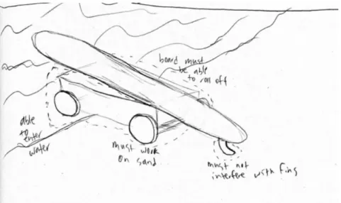
AmpSurf helps veterans and others with disabilities learn to surf. To get those with leg injuries into the water, volunteers push people on a wheelchair to the water and maneuver them onto a surfboard. This is difficult, slow, and requires lots of manpower. AmpSurf volunteers need a way to transport those with lower body disabilities from the beach to the ocean while lying on their surfboard, but it must be cheap, light, small, and reliable. The fins cannot interfere upon departure from the vehicle, and it must be able to be operated by able-bodied volunteers.
Boundary Diagram
Figure 7. Boundary Diagram for Surfboard Sled
The boundary diagram in Figure 7 serves to define where the project begins and ends and the interactions with the environment we are responsible for. The boundary encompasses the sand and water because the device must easily traverse both environments. The dotted line ends at the board and device interface because we are responsible for how the device grips and releases the board, but everything above the bottom deck of the board is not in the scope of this project. An important note is that the fin is encompassed in the boundary diagram because the sled design must allow the board to slide off into the water without interfering with the fins. The sled must also have ergonomic features for volunteers to guide the challenger across the sand and into the water.
Design Considerations
6 wheelchair to a prone position on the surfboard, then they are wheeled into the water until it is deep enough that they can float off on the surfboard.
Some considerations must be noted for the design. Because surfboards have up to three large fins on the bottom, there is a risk of the fins catching on the device as the surfboard slides off. Thus, the sled system should support the surfboard along the sides, where there is no chance of interfering with the fins. Another consideration of the sled design is the variation of surfboard sizes that AmpSurf uses. The program has an inventory of surfboards ranging from eight to twelve feet long, and from 20 to 40 inches wide. Because the product should work for all
surfboard sizes, it may need to be adjustable to accommodate the different sizes. The method for adjustment should be simple and robust, so a volunteer can quickly and easily configure the sled for the necessary surfboard.
There are several other important factors that we will take into consideration when designing and building the surfboard sled. The material should be waterproof and non-corrosive, as it will be subject to saltwater, sunlight, and wind. It should also stand up to vibration subjected from road transport in a trailer. It should be sturdy enough to support a person weighing up to 300 pounds, while being light enough to push on sand and be lifted in and out of a trailer. We will also be considering a factor of safety of 1.5. By including a Factor of Safety in all our calculations we are ensuring that the vehicle could support loads much larger than what they would actually see under normal use, decreasing the chance of failure. A factor of safety of 1.5 to 2 is a reasonable assumption for average materials under average conditions subjected to loads and stresses (Juvinall). The wheels must be large enough to not sink into deep sand. Finally, as the transport trailer is relatively compact and crowded with other AmpSurf items, the system should be compact and possibly collapsible to fit into a small storage volume.
Quality Function Deployment (QFD)
Our team used the quality function deployment House of Quality to translate customer
requirements into engineering specifications. After interviewing our sponsor and observing the environment and board the sled will be interacting with, we came up with a list of needs and wants to satisfy AmpSurf and their participants. In order to create specific and measurable requirements from these needs and wants, we created target values and ranked the importance of each want. For some needs and wants we are not able to create specific target values or test those values, so those needs and wants are design considerations. We will keep design considerations in mind while going through the design process, but we cannot ultimately test them to a
specification. Non-corrosive is an example of a design consideration. We do not have the resources or the time to test if our design will survive in saltwater for a specific amount of time, but we will keep the saltwater environment in mind when selecting materials. The complete QFD chart can be found in Appendix B.
can be easily wheeled into the trailer. The ride height is equal to the height of the beach
wheelchairs the organization uses, so the challengers can easily transfer over to the sled. Ground clearance was set at six inches to accommodate for the changes in surface profile on the beach. The maximum pull force requirement was selected based on Canadian Centre for Occupational Safety and Health, where they state that a standing person with whole body involved can be required to horizontally exert a force of 50 lbf.
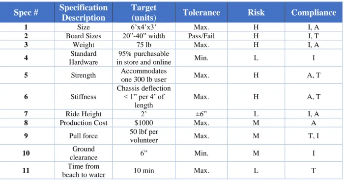
The results of the QFD house of quality have been restructured and entered in Table 1. They are placed in the order of their importance according to the QFD. Each specification has a
8 Table 1. Engineering Specifications
Spec # Specification Description
Target
(units) Tolerance Risk Compliance
1 Size 6’x4’x3’ Max. H I, A
2 Board Sizes 20”-40” width Pass/Fail H I, T
3 Weight 75 lb Max. H I, A
4 Standard Hardware
95% purchasable
in store and online Min. L I 5 Strength Accommodates
one 300 lb user Max. H A, T 6 Stiffness
Chassis deflection < 1” per 4’ of
length
Max. H A, T
7 Ride Height 2’ ±6” L I, A
8 Production Cost $1000 Max. M A
9 Pull force 50 lbf per
volunteer Max. M T, I
10 Ground
clearance 6” Min. M I
11 Time from
beach to water 10 min Max. L T
Specification Table Key
(H= high, M= medium, L= low, I= inspection, T= test, A= analysis)
The specifications listed in Table 1 will be tested through the following processes:
• The weight will be inspected with the SolidWorks mass properties tool, and with a trigger pull scale after it is manufactured
• The board size accommodation will be tested with a measuring tape, and by placing boards of different sizes on the product
• The size, ride height, and ground clearance will be inspected with the measuring tool in SolidWorks, and with a tape measure after it is manufactured
• Purchase receipts will be stored and uploaded to an Excel sheet to keep track of total production costs
• Time from beach to sand will be tested after fabrication with a stopwatch
• Strength and stiffness will be calculated by hand, by use of FEA, and then confirmed with weights and scales after fabrication
• Pull force will be measured by a trigger pull scale after fabrication on a sandy surface
4
Concept Design
Our team used a variety of ideation techniques to gather a large amount of design ideas, then methodically narrowed down the solutions to the best possible ones using decision matrices. Included in this section is a discussion on the processes we used to develop, evaluate, and select our top concepts, with descriptions of the favorable designs and justification for our selected final design we built.
Ideation
We began by gathering as many ideas as possible for the surfboard sled design. However, attempting to brainstorm a final design for the entire system limits creativity, glosses over subsystem characteristics, and limits the number of possible ideas. Thus, we used functional decomposition, the process of breaking down the overall function of a device into its smaller parts. All functions were kept as simple and concise as possible for ease of ideation. For the surfboard sled, we determined that the overall function it needed to achieve is to “traverse beach.” From this overarching requirement, we wrote a number of subfunctions that the sled needed to complete to be able to traverse the beach, like “carry person” and “hold surfboard.” We continued this process until the surfboard sled requirements were defined in the simplest possible group of subfunctions. We documented the process on a large whiteboard, set a timer for fifteen minutes, and sought to individually brainstorm as many ideas as possible to
accomplish each of the subfunctions. No idea was deemed too silly or impractical, and after fifteen minutes, we had over 50 Post-It notes with possible solutions for all aspects of the surfboard sled design. A list of all the ideas created with this method can be found in Appendix C.
After the function-based whiteboard ideation, we utilized a process known as brainwriting to gather more ideas. We identified four of the most important characteristics the surfboard sled needed: board support mechanism, collapsible/adjustable mechanism, volunteer interface, and beach-traversing method. Each of the four characteristics was assigned to a member of the team, and we sketched and wrote descriptions for designs of the systems over a five-minute time interval. We then switched papers and continued with another characteristic, building off our teammates existing solutions. We repeated this process until we had all ideated on each
characteristic, resulting in multiple ideas for each characteristic from each team member. A list of the ideas created with the brainwriting method can also be found in Appendix C.
Idea Refinement and Selection
10 others in comparison to it for each requirement. We then added up the rankings to determine a top design for the function. The four Pugh matrices can be found in Appendix D.
With the top ideas for each of the four important functions selected by the Pugh matrices, we determined the best means of combining each function design into a complete surfboard sled. Through a Morph matrix, we listed and sketched top designs of subsections for volunteer interface, chassis material, accessory material, sand transport method, and board support mechanism. We then drew lines between idea sketches to generate a list of five possible
combinations for an overall design. The Morph matrix is listed in Appendix D. The five design ideas are seen in Figures 8 to 14.
Figure 8. Design 1: rectangular base, sling support, push bars, PVC
Figure 9. Design 1 prototype
Figure 11. Design 3: wheelbarrow base, sling support, push bars, PVC
Figure 12. Design 4: chariot style base, sling support, rail bars, stainless steel
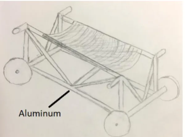
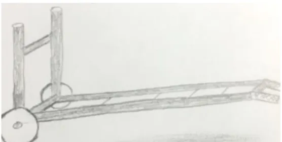
Figure 13. Design 5: rectangular base, slat support, push bars, 80/20 aluminum base, PVC rails
Figure 14. Design 5 Prototype
The last step of idea refinement was to determine the top design using a weighted decision matrix. We listed and sketched the five designs generated from the Morph matrix and copied the criteria from our existing House of Quality chart. Each criterion was given a weighting based on its importance as determined from the chart, then the five designs were ranked out of ten points based on the different criteria. We used Microsoft Excel to automatically multiply the design rank by its criteria weight, then add the individual scores to determine the best possible design. The complete weighted decision matrix is attached in Appendix D. The winning design was found to be a surfboard sled with a rectangular PVC base, four wheels, a tarp for surfboard support, and push bars for volunteers. This design significantly beat out all others with regards to ease of use and adaptability for all surfboard sizes.
Design Description and Justification
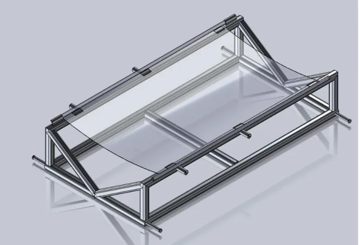
12 sled across the sand and into the water. The tarp is supported by C-shaped channels on one side, allowing volunteers to easily remove it once the surfboard is floating in the water and the load is removed. Removing the tarp allows the surfboard to slide off the device easily, without the fins catching on the frame. The sled is symmetric, so the user can float straight onto the sled to be wheeled back up the beach without any movement of the sled in the water. Figure 15 shows a SolidWorks rendering of this initial conceptual design. The sled is designed to be made from stainless steel.
Figure 15. Initial concept design
Final Concept
Figure 16. Updated Concept Design
The new design is to be made of stainless steel, as the shape of the structure demands a stronger material than PVC. The sled features a ski on the front, which serves two purposes: the ski replaces a wheel, and since the beach wheels we plan to buy are expensive, any reduction of price gives us more room to ensure that other elements of the sled are improved. Additionally, because the wheels are large and buoyant, there is a concern that the sled will float in the water and prevent the user from sliding off. With a ski in the front, the front end of the sled will
reliably sink when in the water. We will test this ski in the near future to determine its feasibility. If we find that the ski does not slide well in the sand, we may convert it to a low-buoyancy plastic wheel that has holes to allow water through. The U-shaped support tubes fit on hinges to fold for storage. The C-channels shown in the CAD model are only a representative of their basic function, but they are still undefined and further research and testing will be done on this
14 Figure 17. Concept design in collapsed state
Concept Geometry and Materials
The only material options from our Pugh matrix were PVC, aluminum, or stainless steel due to their anti-corrosive properties. Because of our decision to slim down the design and make it more aesthetically pleasing, 316L stainless steel was our best choice for the chassis material since we could take out a lot of material and not sacrifice much strength. The square tubing that runs along the length has been selected as 2”x2”x.065” thickness. This is because .065” is the smallest thickness available for 2”x2” square tubing and increasing thickness has the greatest effect on cost. Beam calculations supplied in Appendix F shows that this thickness still has a factor of safety of 3.77. We decided not to size down the outer dimensions of the square tubing from 2”x2” because we need enough width to drill a hole and place a pin into for each of the three support arm hinges.
For the wheel axle that holds the two rear wheels, we selected ¾” Schedule 40 pipe because this gives us a factor of safety of 4.66 and increasing the size of round tubing results in negligible costs compared to the square tubing. Since it only costs a few dollars more to increase width from ½” to ¾”, it's worth it to select the larger size and have a very safe design factor.
A preliminary FEA study was conducted on the main frame and support arms, and it proved to match the hand calculations very closely. Because of this, we are confident that these selected geometries will be more than sufficient to support our weight capacity specification of 300 lbs with a 1.5 design factor.
Manufacturing
skilled welders, we will attempt to use this process first, but if we cannot get good results we will switch to stick welding, which doesn’t require as much skill, and would also be an acceptable process.
Design Changes
Based on feedback from our sponsor, as well as solutions presented at Preliminary Design Review, our design changed from a ski in front to a set of Malone kayak trailer wheels. The ski was originally in our design so that the front would not be buoyant, but our sponsor expressed experience with moving wheelchairs on sand and found the only option that does not dig into sand are wheels with wide surface area. With solid plastic wheels instead of inflatable Malone wheels, we can minimize floating of the front while still allowing for ease of use on sand.
The other major change to the design is the support arms. Originally, the design incorporated round tubing but changed to square cross section tubing to better connect with the square wraparound bracket and center cross beam. Originally, we incorporated collapsible swing arms for storage, but found that the added complexity would lead to much greater probability of failure and concerns with holding design weight. Additionally, the sponsor stated that because the design can be stood up lengthwise, it should fit in the trailer.
5
Final Design
16
Final Design
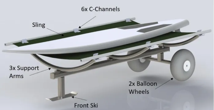
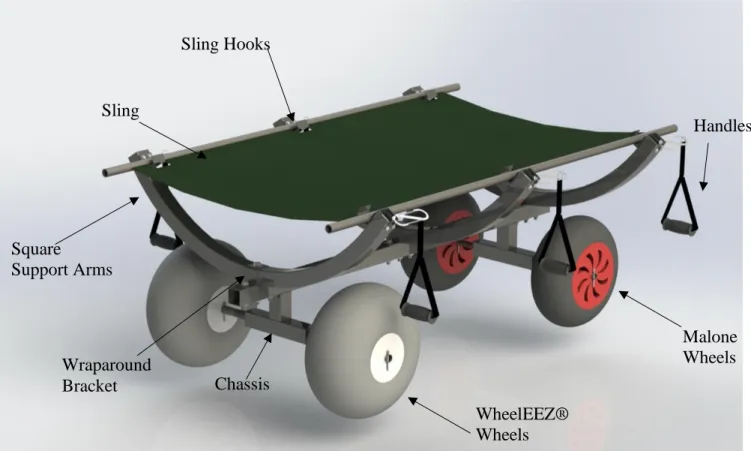
Figure 18. Final design with major components labelled.
The complete design in Figure 18 includes three major subsystems, the chassis, support arms, and sling. Attached to these subsystems are the wheels, handles and wraparound bracket. The chassis and square support arms are 304 stainless steel with 0.083” wall thickness. The design incorporates two sets of wheels, the inflatable WheelEEZ® and hard rubber compound Malone wheels. Both wheels have internally housed bushings and are attached to the front and rear axle via interference fit and cotter pins to hold the wheels in place. The handles are attached to the square support arms with carabiners which are fed through holes in the tubing.
Handles
Malone Wheels
WheelEEZ® Wheels Square
Support Arms Sling
Sling Hooks
Wraparound
Chassis
Figure 19. Stainless Steel Chassis and Axles
The center beam of the chassis in Figure 19 is a 2”x2” square cross section beam with 0.083" wall thickness. The beam force calculations in Appendix F show that a beam of 0.065” has adequate strength to withstand our maximum design weight of 300 pounds while maintaining a factor of safety of 3.8, but since we were donated 0.083” thickness squaring tubing, we decided to use that instead as it will only make the structure stronger and would add only negligible weight. The T- shaped axle interface is the same 2”x2” square cross section tube welded to the center beam. Each end of the axle interface has a stainless steel cap welded to the stainless steel axle. Holes on top of the center beam are for the square wraparound bracket to bolt on the support arms. There are also many smaller holes along the underside of all the square tubing so that it can drain ocean water sufficiently. Full dimensioned drawings for this part, and all other manufactured parts can be found in Appendix H.
Square Support Arms
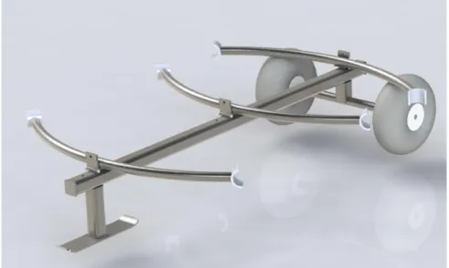
Figure 20. Square Support Arms Assembly
The support arms in Figure 20 are 2x2 inch square cross section 304 stainless steel tube bent by Tube-Tec. The exact geometry of the bent tubes is shown in Appendix H. We selected square tubing in order to have continuity with the main center beam. Bolted to the end of each support
T- shaped axle interface
Center beam
18 arm is a sling hook that holds the weight of the challenger on the vehicle. The hook allows the sling to be lifted off and detached to begin surfing.
Figure 21. Square Wrap Around Bracket fastened to support arms and chassis
The square tubing is attached to the center main beam with a square wraparound bracket instead of welding, which allows for strength while minimizing rust prone areas and the heat affected zone. The bracket and its attachment to the chassis is seen in Figure 21.
Sling
Figure 22. Sling
There are six square cutouts to allow for the sling hooks to pass through. Each cutout includes a zig-zag stich around the perimeter to eliminate fraying.
Figure 23. Sling Hooks Bolted to Square Support Arms
The sling hooks in Figure 23 fit inside of the square cutouts on the sling and allows the tarp to be lifted off when in the water or for storage. The edges of the sling hook will be chamfered to avoid any ripping of the sling. See section 8-2 for more details on the Sling design, as this portion of the project was not completed due to the Covid-19 outbreak.
Wheels
The Beachin’ Buggy features two types of wheels, as seen in Figure 18. The WheelEEZ® wheels are inflatable and more buoyant while the Malone wheels are solid rubber and plastic, allowing for sinking. This design choice is so that the front of the device will sink once it reaches a few feet of water. The wheels are slid onto the front and rear axles and held in place with cotter pins.
Handles
The interface volunteers interact with are standard gym equipment handles. They are attached to the square support arms using a carabiner. The handles have a textured rubber grip for ease of use by volunteers, as well as multiple attachment points so volunteers of various heights can comfortably and safely maneuver the device.
Safety and Maintenance
20 Volunteers assisting in pulling the vehicle should always pull by the handles to avoid pinch points near the carabiner. Awareness of the wheel location is also important to prevent toes or feet from being rolled over. These safety concerns are detailed in the Design Hazard Checklist located in Appendix E.
The handles and carabiners are off the shelf components and can be quickly replaced if necessary. The supplier and part name are described in the Indented Bill of Materials found in Appendix J. The sling can be repaired with a catamaran trampoline repair patch, however if larger rips occur, we recommend contacting SLO Sail & Catamaran to have the sling rebuilt on the existing Sling Rods. The WheelEEZ® tires should be inflated between 2-4 psi as printed on the tire. Check air pressure monthly or if any tire appears to deform excessively.
Cost
The total cost for the final product including R&D is $1,941. The detailed breakdown of cost by each part and subassembly can be found in the Indented Bill of Materials located in Appendix J.
Table 2. Cost Breakdown
Structure $1465
Sling $300
Labor $150
Structural Prototype $26
Total $1,941
Changes Post-CDR
6
Manufacturing
This section details the process behind purchasing parts, building, and assembling the surfboard sled, with consideration for all used components.
Procurement
Per the Indented Bill of Materials in Appendix J, our main suppliers for purchased parts were WheelEEZ®, Malone Auto Racks, Valley Iron, OnlineMetals, Tube-Tec, SLO Sail and Canvas, and FitnessFactory.com. All other miscellaneous parts to complete the surfboard sled will be purchased from McMaster-Carr. These include sheet stainless for the main brackets, bolts, nuts, washers, cotter pins, and carabiners.
Manufacturing
This team completed some manufacturing components in the Mustang ‘60 or Aero Hangar machine shops at Cal Poly. However due to the Covid-19 pandemic we completed the rest of the manufacturing process at our own home. This proves that this project does not require a shop with sophisticated equipment and can be completed using common house tools. However, there are some tools that will make the work easier and faster. This team used a power saw with an abrasive wheel to cut all tubing to length. Much like the one used in Figure 24 by our
teammate Griffin O’Malley. This is the fastest method for cutting stainless steel.
Figure 24. Griffin cutting the chassis with cold saw Figure 25. Marius angle grinding sling hooks
22 holes for the pins in the axel. To create the Sling hooks we recommend using a vise and a angle grinder to cut the square stock. Our team made sure to cut away the seam of the tube to avoid warping. Line up your cut with a clear line of site much like in Figure 27 as Jose Covarrubias is showing. Once you are ready you can start cutting making sure the sparks fly away from your body and you are wearing proper PPE, much like Marius Jatulis is doing in Figure 25.
Figure 26. Arthur drilling pin holes in axles after they were turned down
Figure 27. Jose angle grinding more sling hooks
Due to the global pandemic our team used unconventional methods to manufacture the frame. Each whole was drilled with a 20V hand drill with the Milwaukee Cobalt drill set. By starting with a small 1/8th inch drill bit and slowly increasing the size until we reached the ½ inch
hole. The team members had to apply maximum downward pressure on the hand drill which low speed. The team also constantly use lubrication and water to keep metal from work hardening. An example of this setup can be seen in Figures 28 and 29 as Jose Covarrubias and Marius Jatulis are shown working hard to drill into the frame. All cuts can be done with an angle grinder, however they will require several cutting and grinding disks.
Files and other deburring tools were used trough out the project to keep the parts safe from sharp edges. Without a drill press it may take each ½ inch hole up to 20 to 30 mints to drill. If the steel work hardens from insufficient amount of lubrication and improper speed, then the lead time by rise to 40 to 60 minutes each hole. Our team adapted to the pandemic conditions while keeping safety our priority. We were able to complete the manufacturing of the entire skeleton. QL+ will have to outsource the manufacturing of the sling assembly and complete testing on their own. A full list of manufacturing procedures for the Surfboard Sled can be found in Appendix K: Manufacturing Plan. Most operations are relatively simple, and any difficult operations will be outsourced as described in Section 6.4.
Assembly
A full list of manufacturing and assembly steps can be found in Appendix K: Manufacturing Plan, and Appendix N: Operator’s Manual. The Surfboard Sled is assembled initially in three main subsystems: the chassis, support arms, and sling assembly. These are combined from the ground up to finish the overall sled assembly.
Outsourcing
Welding stainless steel is difficult and important to perform well, or the welds can crack under stress, resulting in a significant failure of the device. Thus, we are outsourcing the welding for the chassis and axle assembly to ensure the longevity of our design. We are paying Gentry Welding & Fabrication in San Luis Obispo, a highly recommended fabrication shop, to complete the necessary welds.
Another outsourced operation is the bending of the support arms. Because of the square tube profile and the strength of stainless steel, Cal Poly does not have the equipment necessary for bending the arms. Instead, we are buying the tubes from Tube-Tec in Houston, TX, who will supply and bend the tubes according to our specified dimensions.
Due to the Covid-19 epidemic we were not able to bend the wraparound brackets ourselves. We outsourced this work to Borden Precision Products Inc., which is a fabrication shop in San Luis Obispo. They generously donated their service to our project.
7
Design Verification
This section will describe the test procedures that that will implement in order to create a proper device. We will discuss how to test our final product as well as describe results from our test on the structural prototype.
Testing
In order to provide a safe product for the customers, a series of test must be performed to ensure a high level of quality. The Failure Modes and Effects Analysis (FMEA), shows that the three highest areas of concern were the ability for the wheels to traverse the beach and ocean, the ability of the sling system support to hold 300 pounds, and how well the frame supports the rider. More details of the FMEA can be found in Appendix I. Once the initial product is created,
24 An important test that must be done is the strength test. It is critical that the sling, frame, and wheels are all be able to support 300 lbs. with a factor of safety of 1.5. Once the frame is built and the wheels are attached, we will place weights on the sling until it reaches the rated maximum weight. The test of the wheels will be done at an earlier stage with the structural prototype, which will be discussed later in this report. The weights will not only test the sling, but the frame as well. Once we gain the results of the test, our team will adjust our design and add support as needed.
The next test that must be completed is the pull test. In a past meeting with our sponsors, they expressed concern that the pull method may cause injury to the volunteers. We will take spring scales and measure how much force is required to move the device with a full load across sand. We want to make sure that it takes less than 50 lbs. of force to move the prototype. This will comply with our safety concerns expressed by our sponsor. Our team will use the device as intended and decide if it is too strenuous to pull. This test will be purely based on our feel of the device.
The last test that will be performed is a full function test. Our team transport a person with a surfboard and attempt to pull them in and out of the water. This will provide us with the data to create a procedural instruction manual that we can give to our customers. Many of the tests can be performed on our structural prototype, not requiring the finished model.
Prototype Specifications
Figure 30. Structural Prototype
We fabricated the frame by modifying a table and adding structural integrity with 2”x4” wood support posts. We cut the legs to fit our design height of 24” and to fit the desired axle length. In the front the Malone wheels were set 17” apart and in the back the WheelEEZ® were set 20” apart. The front axle was modified from a piece to galvanized steel pipe from Home Depot. While this is not the material that will be used for the final project, it was a cheap alternative to test the wheels and sand interaction. The rear axle is a 1.05” outer diameter pipe that was turned down to 1.00” on the lathe. This axle is made of stainless steel and will be reused for the final project. The fully dimensioned drawings of these axles are seen in Appendix H. Four holes were made at the corners of the tabletop and handles were attached with rope. The handles in the final model will be attached to the vehicle with carabiners; however, the rope was enough to test the prototype. The test has been broken down in our Design Verification plan (DVP) in Appendix L.
On February 1st our team took our structural prototype that can be seen in Figure 30 to Morro Beach, CA. The intention was to test the ability of the wheels to support the desired weight, and how it will react in the ocean. We initially put on 300 pounds of weight on the prototype and tested how difficult it was to pull across the sand. Another concern we wanted to test if the handles were high enough so an average person can pull the device without producing the danger of back strain. After our experiment we can conclude that the wheels provide enough slip so that it is not too strenuous for two people to pull 300 lbs. These tests were only to get a preliminary idea of the pull force required, but the actual number will still need to be found through tests with a spring scale. The final product will have the capacity for 6 people to pull the device which will provide enough redundancy to be safe. We also concluded that the wheelbase provides enough stability so there will not be any danger of tipping. Our team then moved the prototype in and out of the ocean with the 300 pounds on the board.
We concluded the design satisfied the needs to traverse the ocean floor. We also concluded that it is always optimal for the WheelEEZ® to be in the back of the device no matter what direction it is moving. This is because WheelEEZ® compress and can work better when the load is directly on top of them. Overall, we successfully proved our design concepts for the final product.
The next test is to create the sling hooks in which the sling will sit on from our square pipe. Our goal is to gain analytical data to see when the hooks will break. From there we will be able to perform an uncertainty analysis on the hooks to make sure they are safe to use. A full description of these tests are in Appendix M. The timeline of these future tests are outlined in the Gantt chart seen in Appendix G.
8
Work To Be Continued
26
Sling Procurement and Manufacturing
All parts were purchased, manufactured, and assembled already besides the Sling. When the pandemic hit California, our Sling source, SLO Sail and Canvas, notified us that they could no longer complete our job as they had to strictly focus on essential business. Once they can start working on our job again, individuals will need to purchase the two 60” long 3/4” nominal Sch. 40 aluminum pipes from OnlineMetals and take the assembled Skeleton and these two Sling Rods to the warehouse for them to fit the Sling to. The link to these two Sling Rods can be found at the end of the drawing package in Appendix H. After talking with SLO Sail and Canvas, we determined it would be best for them to fit the sling canvas onto the physical Skeleton in-person, instead of following strict drawing dimensions, as the final product could be out of tolerance and the Sling wouldn’t fit the cutouts for the Sling Hooks on the Support Arms. The material of the canvas was not finalized since we could no longer visit their store and discuss options, but we determined that any of their catamaran trampoline materials would work for our project as long as it could support a 300 lbf load and provided sufficient corrosion resistance. It is essential that the 6 cut-outs in the sling canvas align well to the Sling Hooks and are reinforced to prevent tearing.
Attaching the sling canvas to the rods could be accomplished in any manner that the experts at the location think would work best. The attachment technique our team envisioned is illustrated in Figure 31. They would loop the canvas around the sling rods and stitch it back into itself, making sure to create the six reinforced cutouts beforehand. $300 has been allocated in the budget for this job, which includes the cost of the two Sling Rods ($16.79 ea.) and their shipping costs.
Figure 31. Sling Attachment Method
Additional Testing
Modes and Effects Analysis, is the Sling Tearing Test. It is critical that this test occurs before a person lays on the sling and operates this device.
9
Project Management
This section describes the devices our team used to stay on track and ensure all parties involved with our project were informed and aware of our progress. It also contains a table of the key deliverables that were required throughout the process.
Design Process
Our design process encompasses four main phases: collecting, designing, building, and testing. The collecting phase includes background research, searching existing designs and patents, and defining project goals. This phase culminated in the Preliminary Design Review document which summarized what we learned and outlines the fundamental goals our design must accomplish. In the design phase, we generated ideas for our design and created preliminary sketches. Once we decided on a promising and feasible design, we built smaller scale concept models to get a sense of how difficult manufacturing the design is. With the models, we completed basic scale testing and observed potential problems. A preliminary CAD model was then created based off the scaled concept models. The building and testing phases were iterative processes that we continued to repeat until we had a design that meets Mr. Cummings’ goals. After a design was finalized, we created our structural prototype that tested out a few key qualities: the tire
maneuverability on sand, the ride height, the handles, and the buoyancy of the wheels in the ocean. Testing procedures were developed based on tests we deemed appropriated in the Design Verification Plan section. Final prototype manufacturing occurred throughout this testing phase, and afterwards as more shipments of our parts came in.
The COVID-19 outbreak caused significant problems with our original project management plan. At the time school was shut down we had already purchased almost every single part with the plan to alter and manufacture in the Cal Poly SLO machine shops. Once the shops shut down we had to either outsource certain jobs, or change our manufacturing processes to adjust to the available tooling. This led to many days manufacturing in a parking lot with simple drills and wrenches, since we weren’t allowed to use most other power tools as it posed a liability issue. This outbreak also had huge effects on our sling procurement. The plan throughout the project was to finish all manufacturing beside the Sling, and then take the finished product and let SLO Sail and Canvas fit the Sling to it on the spot. Once their business partially closed down, we could no longer deliver our product and get the Sling fitted and manufactured. Due to this, we had to make a guide on how to finish this job for a person in the future when their business allows for it.
Timeline
28 building up to each milestone are linked to show the flow of the project. After the COVID-19 outbreak, we steered away from the Gantt Chart for the most part, and instead opted to have weekly meetings with our advisor to discuss what future tasks on the chart are feasible and which ones must be delayed.
Table 3. Deliverable Due Dates
Key Deliverables Due Date
Interim Design Review 1/16/2020
Critical Design Review 2/4/2020
Manufacturing & Test Review 3/12/2020
Webpage submitted 5/28/2020
Final Design Report 6/4/2019
The Interim Design Reviews and Critical Design Reviews serve as two major checks on our design where we got feedback on our direction and overall progress. The Manufacturing and Test Review is a short presentation we conducted that shows our progress we have made on manufacturing. The Project Expo/Final Design Review is the final deliverable for this project. This is the day we turn in our final report and display our final prototype model. After this event we will be delivering our prototype to the AmpSurf organization for their use.
Next Steps
Continued communication with Ms. Salas and Mr. Cummings will be important to make sure all parties are up to date with where we left off our project. If it were not for the unique
circumstances, we would have been able to deliver a finished product to our sponsors at this time. Unfortunately, that is not the case, and there is still work to be done. We are confident that we made great progress despite the limitations, and that we are leaving this project in a 99% completed state.
10
Conclusion
This document provides an overview of our progress on the project, including a highly detailed description of our final design. This team created a sled that will help disabled veterans lay on top a surfboard on land and transport them into the water. It can accommodate a variety of surfboard sizes and withstand a heavy load while being lightweight and cost effective. This report details the requirements we met, and those that were not met due to limitations this quarter. This report has also been delivered to QL+ and AmpSurf to serve as both a user manual (Appendix N), and a guide for future work (Section 8).
Lessons Learned & Recommendations
30
References
“Beach Wheelchair Conversion Kits By WheelEEZ® with 49cm Wheels.” WheelEEZ®, Inc. | WheelEEZ® Low-Pressure Wheels, WheelEEZ®.com/product/beach-wheelchair-conversion-kits-by-WheelEEZ®-2.
Cummings, Dana. “AmpSurf Interview.” 6 Oct. 2019.
“Florida Sailcraft.” Florida Sailcraft Jet Ski Beach Trailers Florida Sailcraft, floridasailcraft.com/product/tiger-tote-jet-ski-dolly/.
“Get to Know the ADA Wheelchair Ramp Requirements.” Ideal Shield, 24 Jan. 2017,
www.idealshield.com/get-to-know-the-ada-wheelchair-ramp-requirements/.
“JetLift.” JetLift, www.thejetlift.com/.
Juvinall, Robert C., and Kurt M. Marshek. Fundamentals of Machine Component Design. 5th ed., John Wiley & Sons, 2012.
“MIG Welding with 100% Argon Shielding Gas • WelditU.” WelditU, 9 Nov. 2019, welditu.com/welding/tips-mig/mig-welding-with-100-argon/.
“Pushing & Pulling - General.” Canadian Centre for Occupational Health and Safety, 3 Apr. 2017, www.ccohs.ca/oshanswers/ergonomics/push1.html.
Seay, Sean V. “Association Between Adaptive Sports Programs and Quality of Life Among Amputee Veterans.” Walden University Scholar Works , 2018
Stathopoulou, Georgia, et al. “Exercise Interventions for Mental Health: A Quantitative and Qualitative Review.” Clinical Psychology Science and Practice , 30 May 2006, doi:
https://doi.org/10.1111/j.1468-2850.2006.00021.x
Valeski, Brennan. “Average Jet Ski Weight (With 10 Examples).” Survival Tech Shop, 9 Nov. 2019, www.survivaltechshop.com/jet-ski-weight.
Relevant Patents
Patent Number Patent
Title Description Drawing
US20070296167A1 Road and sand sled
This is a sled that can move on sand and common roads. It is raised from the ground that allowed for clearance to go over obstacles. This is meant to hold light cargo as it is being pulled along the sand.
US6869084B2 Dignified broad footprint beach wheelchair
A wheelchair with skids, is equipped with a spring-loaded roller. Two front skids in place of front wheels are compressed to provide a resistance-free, broad footprint in the sand and a low-resistance narrow footprint when used by hard.
US9554954B2 Convertible wheelchair
A-2
Patent Number Patent
Title Description Drawing
US20100059950A1 Modular beach cart system
This is a cart that is meant to hold surfboards and transport them over the sand.
US8382135B1 Sand-rideable bicycle
A sand-rideable bicycle utilizes oversized balloon tires that have an enlarged footprint to permit the bicycle to ride up over even loose sand to provide ease of pedaling as well as enhanced steering and stability.
US4911348A Adjustable cross rail for luggage carrier
An adjustable cross rail for a luggage carrier which utilizes a self-storing lever to release the rail stanchions. The stanchions cooperate with a longitudinal track which receives
Patent Number Patent
Title Description Drawing
US20170254347A1 Mounting fixture of a connecting feature
Clamp for round bar that something could be attached to. This could be useful if we need to attach hooks to round pipe on the vehicle chassis
US7329161B2 Amphibious recreation vehicle
An amphibious passenger vehicle having several open or covered holes and a surrounding cover to accommodate fishing and hunting.
US3273908A Sand cart A cart that moves on sand and holds a load with a rectangular shape.
US4719954A Awning assembly with telescoping support arms
An awning assembly which is particularly suited for
B-1
Ideation List
• Tow t-bar
• Bike pedals
• Chest harness
• Wheels that turn themselves
• Carry directly
• Solar powered motor
• Gas engine
• Push handles
• Ripstick-like motion
• Pulley system
• Rocket engine
• Magnets
• Track from beach to water
• Wind up motor
• Pull like a wagon
• Rubber band assisted motion
• Pedal you step on a bunch of times
• Trebuchet
• Slide rails
• Team of sled dogs
• Tank treads
• Caster wheels
• Blow up wheels
• Levers the rider pushes with hands
• Propulsion rockets
• Catapult
• Mat from beach to water
• Skis
• Wheels that strap to board “wheel board”
• Tesla batteries
• Throw person
• Elliptical bars
• Motor and pulley
• Walking machine
• Pontoons
• Winch
• Giant fan
• Electric motor
C-2 Brain Writing:
a) Adjustable/Collapsible Mechanisms
i) Ratchet board (swing up for different sizes) ii) Pin & slot system with telescoping arms iii) Hinge in center (folds length-wise)
iv) Hinges at front and back (folds width-wise) v) Fin slot down center
vi) Tri-fold
vii) Scissor arms to expand and contract the width viii) Spring loaded cross beams and pin lock system b) Volunteer Interface
i) Contoured grab handles ii) Backpack support straps iii) Shopping cat push bars
iv) Push bars extending from corners v) Ropes
vi) Drywall carrier handles vii) Winch
viii) Pulley system ix) T bar to pull
Pugh Matrices:
D-2
Material
PVC 80/20 Alum. Round 316 SS 304 SS
Weight 10 5 5 1.75 1.75
Cost 10 0 5 4 5
Strength 2 9 9 10 8
Stiffness 0 3 3 10 10
Manufacturability 10 7 5 5 5
Corrosion Resistance 10 5 5 9 2
Hardware Compatibility 10 9 9 7 7
Repairability 10 3 3 3 3
Sum 62 41 44 49.75 41.75
Durable 0 - - + -
-All Board Compatibl e
0 - - + -
-Price 0 + + - + +
Manufactu rable
0 + - - + +
Easy to pull
0 - - - -
- Non-corrosive
0 S S - S S
Sand-Resistant
0 - - + -
-Good ride experience
0 - - S -
-Compatibl e with wheel chair
0 - - + -
-Sum 0 -2 -4 -2 -3 -4
D-4
D-6
Weighted Decision Matrix:
Reasoning for Assigned Values
Lightweightedness Based off material density, and number of wheels. Average value used for #2&4 Size of Vehicle #3 is smaller due to ability to stand upright easily in trailer. #4 would be smaller
also, but it needs to be as long as the entire board length, unlike #3 Cost Based off of material cost/lb, and # of wheels
Time from Beach to Water
#1,2,5 do not need to be picked up, and are constantly at perfect height. #1,2,3,4 need to be unhooked at departure. #5 needs to be set up at beginning, but not departure
Strength Based on ultimate tensile strength of each material. #2, #5 use average value Stiffness Based on module of elasticity of each material. #2, 5 use an average value Pull Force #3, 4 need to be picked up as well as pulled/pushed
Standard Hardware Everything can be used with pvc (#1,3). #2 round stock to pvc fittings may not be standard. #4 steel stock to pvc fitting may not be standard. #5 80-20 stock to pvc fitting may not be standard
Ride Height #3,4 would be at an angle when loading, and would not constantly be at the best ride height
Ground Clearance #3, 4 the frame that hangs down and the vehicle rests on may not be very high off the ground when the wheelbarrow is picked up
Y N
1. Will any part of the design create hazardous revolving, reciprocating, running, shearing, punching, pressing, squeezing, drawing, cutting, rolling, mixing or similar action, including pinch points and sheer points? 2. Can any part of the design undergo high accelerations/decelerations? 3. Will the system have any large moving masses or large forces? 4. Will the system produce a projectile?
5. Would it be possible for the system to fall under gravity creating injury?
6. Will a user be exposed to overhanging weights as part of the design? 7. Will the system have any sharp edges?
8. Will any part of the electrical systems not be grounded?
9. Will there be any large batteries or electrical voltage in the system above 40 V?
10. Will there be any stored energy in the system such as batteries, flywheels, hanging weights or pressurized fluids?
11. Will there be any explosive or flammable liquids, gases, or dust fuel as part of the system?
12. Will the user of the design be required to exert any abnormal effort or physical posture during the use of the design?
13. Will there be any materials known to be hazardous to humans involved in either the design or the manufacturing of the design? 14. Can the system generate high levels of noise?
E-2
Description of Hazard
Planned Corrective Action Planned Date
Actual Date
The surfboard sled will be rolling across the beach holding the weight of a full person and a surfboard. We are designing this project with the criteria that it will hold 300 lbs. The volunteers helping push the sled are bare foot and if not careful may have their foot run over by the sled.
We will create handrails and push points away from the wheels. We will also create a comprehensive instruction and warning guide for the volunteers so they can use the equipment in a safe way.
12/1/2019 6/3/2020
This system will be designed to hold 300 lbs.
The project will be made out of materials such as stainless steel, aluminum, and furniture grade PVC. We will not use any material that does not fit the strength criteria. We will also test our system before giving it to our customer.
12/1/2019 INC
The person using the device will be suspended in the air about two feet. If a fail point occurs the person may bump their head or injure themselves.
We will reinforce all contact points to make sure the device is as safe as possible. We will also recommend there be no less than six volunteers be present in helping the user be safe. This will go in our instruction and warning guide.
12/1/2019 6/3/2020
Most users of the surfboard sled will be amputee veterans where they may be missing one or all limbs. In this case they will be required to use
whatever means they feel comfortable to get on the device. This may result in abnormal physical movement.
Currently we have planned to use a self-centering sling that will provide the maximum stability for the board. We will also create the sled height the same as the beach wheelchair already in use by our sponsor. This will make sure the transition from the wheelchair to the sled will be as smooth as possible.
12/1/2019 6/2020
Our system will be required to go into the ocean water and be driven in the sand.
To counteract the corrosion created by saltwater we plan to use non-corrosive materials. We are also looking into anti-corrosive paints and sprays that will also help reduce this danger.
Description of Hazard
Planned Corrective Action Planned Date
Actual Date
This system will be made out of heavy and sturdy material that will be on wheels. If
someone were to engage in horseplay or tomfoolery around the
device and start using it for things other than its intended purpose, this may cause injury.
We are not responsible for the misuse of our product. All we can do is educate the users on the safe and proper way to use the device.
F-1
G-1
Assembly Level
Part
Number Qty Cost ea. Ttl Cost Source
Lvl0 Lvl1 Lvl2 Lvl3
0 100000 Beachin Buggy Assy v7 1
1 110000 Skeleton 1
2 111000 Chassis 1
3 111100 Main Frame 1 0 0 ValleyIron
3 111200 End Cap Rear 2 14 28 TopHardware
3 111300 End Cap Front 2 14 28 TopHardware
3 111400 Axle Rear 1 0 0 ValleyIron
3 111500 Axle Front 1 70.68 70.68 OnlineMetals
2 112000 Support Arm Assy 1
3 112100 Square Support Arm 3 243.3333 730 Tube-Tec
3 112200 Handle 6 11.99 71.94 FitnessFactory
3 112300 Sling Hook 6 0 0 ValleyIron
3 112400 Carabiner 1 6-PACK 10.95 Amazon
3 112500 316 Stainless Steel Hex Head Screw1/4"-20 Thread Size, 2-1/2" Long, Partially Threaded 2 10-PACK 9.56 McMaster
3 112600 316 Stainless Steel Washer for 1/4" Screw Size, 0.281" ID, 0.625" OD 1 100-PACK 7.11 McMaster
3 112700 316 Stainless Steel Hex Nut 1/4"-20 Thread Size, ASTM F594 1 50-PACK 4.08 McMaster
2 113000 Square Wrap Around Bracket 1 23.53 23.53 Amazon
2 114000
316 Stainless Steel Hex Head Screw 1/2"-13 Thread Size, 3" Long,
Partially Threaded 6 1.46 8.76 McMaster
2 115000
316 Stainless Steel Washer for 1/2" Screw Size, 0.531" ID, 1.25" OD
1 25-PACK 8.16 McMaster
2 116000 316 Stainless Steel Hex Nut 1/2"-13 Thread Size 1 10-pack 4.52 McMaster
2 117000
316 Stainless Steel Hex Head Screw 1/2"-13 Thread Size, 5" Long,
Partially Threaded 3 2.47 7.41 McMaster
2 118000 Rubber Sheet 1 Sheet 15.53 McMaster
1 120000 WheelEEZ 16.5in_1in_axle 2 164.34 328.68 WheelEEZ
1 130000 Malone All Terrain YakHauler 2 50 100 Malone
1 140000 316 Stainless Steel Cotter Pin3/16" Diameter, 2" Long 1 10-PACK 8.83 McMaster SLO Sail & Canvas
OnlineMetals
1765.74
= Manufactured/Altered Part
TOTAL COST Beachin' Buggy
Indented Bill of Material (iBOM)
4 8X 1 1X
3 2X
2 2X
ITEM NO. PART NAME PartNo QTY.
1 Skeleton 110000 1
2 WheelEEZ 16.5in_1in_axle 120000 2
3 Malone All Terrain YakHauler 130000 2
4 98355A250 140000 8
5 Sling 150000 1
Part #: 100000 Drwn. By: A ZAAYER
Part: Beachin Buggy Assy
BEACHIN' BUGGY
Cal Poly Mechanical Engineering
6 9X 2 1X 3 3X 7 3X 1 1X 4 6X 5 9X
ITEM NO. PART NAME PartNo QTY.
1 Chassis 111000 1
2 Support Arm Assy 112000 1
3 Square Wrap Around Bracket 113000 3
4 92186A724 114000 6
5 90107A033 115000 9
6 94804A340 116000 9
7 92186A732 117000 3
Part #: 110000 Drwn. By: A ZAAYER
Part: Skeleton
BEACHIN' BUGGY
Cal Poly Mechanical Engineering
Cost: Material: 304 SS
1 3 2X 2
2X ANGLES 5
2.
12.813 13.000±.250
13.000±.250 10.000±.250
10.000±.250 9.813
18.000
4 2 1
2X 3 2X 5 A DETAIL A SCALE 1 : 4 .13
4X
.13 4X
ITEM NO. PART NAME QTY. PartNo
1 Main Frame 1 111100
2 End Cap Rear 2 111200
3 End Cap Front 2 111300
4 Axle Rear 1 111400
5 Axle Front 1 111500
Part #: 111000 Drwn. By:
Part: Chassis
BEACHIN' BUGGY
Cal Poly Mechanical Engineering
5.000±.050 1 2 3 A 1 2 3 3 8.000 8.000
7.000+-.250.000 7.000+-.250.000
3
1
DETAIL A SCALE 1 : 4 .13
2X
UNLESS OTHERWISE SPECIFIED: DIMENSIONS IN INCHES .XXX .005
1.
ANGLES 5 2.
ITEM
NO. QTY. DESCRIPTION LENGTH
1 1 TS2x2x0.065 60
2 2 TS2x2x0.065 3.5
3 2 TS2x2x0.065 10
Part #: 111100 Drwn. By: A ZAAYER
Part: Main Frame
BEACHIN' BUGGY
Cal Poly Mechanical Engineering
Cost: Material: 304 SS
60.000±.250
1.875
2.125 TYP. 2.125
TYP. 53.875
27.875 .500+-.000
THRU 9X
1.000 .015 A B
A
B
10.000 4.000
10X .250 .065
10X (DRAIN HOLES)
1.000 10X .125 A B
ITEM NO. 1
Part #: 111100 Drwn. By: A ZAAYER
Part: Main Frame
BEACHIN' BUGGY
Cal Poly Mechanical Engineering
3.500±.100 2.000
STOCK
ITEM NO. 2
Part #: 111100 Drwn. By: A ZAAYER
Part: Main Frame
BEACHIN' BUGGY
Cal Poly Mechanical Engineering
Cost: Material: 304 SS
2.000 STOCK
1.250 1.250TYP. 1.000
7X
.500 .065 7X .125 A B A
B
ITEM NO. 3
Part #: 111100 Drwn. By: A ZAAYER
Part: Main Frame
BEACHIN' BUGGY
Cal Poly Mechanical Engineering
1.070 1.050 THRU
1.000
1.000
2.000 2.000
.014 A B
A
B NOTE:
UNLESS OTHERWISE SPECIFIED: DIMENSIONS IN INCHES 1.
.XXX .005 1.
ANGLES 5 2.
STOCK END CAP PURCHASED, DRILL IS ONLY OPERATION. 2.
Part #: 111200 Drwn. By: A ZAAYER
Part: End Cap Rear
BEACHIN' BUGGY
Cal Poly Mechanical Engineering
Cost: 14.00 Material: 304 SS