The Case for Measurement and Analysis of ESD Fields in Semiconductor
Manufacturing--Update
Timothy J. Maloney
Center for Analytic Insights
Palo Alto, CA USA
[email protected]
Abstract– A destructive Charged Device Model electrostatic discharge event can happen in semiconductor manufacturing and should be detectable from radiation that results from collapse of an electric dipole. The analytically describable radiation field pulse of CDM can be readily produced with a new instrument (CDM Event Simulator or CDMES) that creates dipole collapse at will. A coaxial monopole E-field antenna’s transfer function gives the antenna signal in near-field, and experiments compare well with theory. These practices and instruments for CDM ESD monitoring and process control are updated from the original review paper, presented at the 2018 IEEE EMC Symposium.
Keywords – electrostatic discharge (ESD), charged device model (CDM), step response, Laplace Transforms, semiconductor manufacturing, E-field antenna, ESD detectors.
1. SUMMARY
In 2018, the author presented an invited review of ESD field detection and its use in semiconductor manufacturing for the IEEE EMC Symposium in Long Beach, CA, July 2018 [1]. That publication is copyrighted by the IEEE but is accessible, along with related publications from the author, as described at the end of this work. The objective of this work is to alert the reader to the subject, describe its history and major background publications, and offer a few comments on likely future developments for ESD field detection in semiconductor manufacturing.
An early publication occurred in the mid-2000s [2] when the author and a co-author were unsatisfied with the entirely empirical and experience-based use of ESD antennas in their semiconductor company's manufacturing sites, and wrote up some systematic studies. For some time, a ball antenna (common in EMC labs) and oscilloscope had been used on the factory floor (e.g., socketing operations in assembly and test) to give rough feedback on whether it was time to swap out belts and other expendables that might be wearing out and building up too much electric charge. Figure 1 comes from a patent, discussed later, that begins with a sketch of the basic concept of an antenna set up near equipment. In describing these operations in [2], it became clear that
we had much yet to discover and understand about how the discharge currents into devices relate to fields generated and signals produced at the antenna. Over the next number of years, our understanding improved.
Fig. 1. From [9]; setup of antenna and field detector near a manufacturing station that may cause CDM events.
A noteworthy moment arrived in late 2010, when the author reviewed some preliminary work from another company, aimed at reporting on field detection of a CDM pulse generated reproducibly by a CDM tester. The present author had made some progress in understanding the path from static charge to pulsed dipole current, to E-field, to antenna response to the E-field, and was able to interpret some of his colleagues' data accordingly. This was acknowledged in their 2011 publication at the EOS/ESD Symposium [3], and made clear the industry-wide interest in the subject. By that same time in 2011, this author's analytical treatment of fields from pulsed dipoles was also published, as a cover article in an IEEE EMC magazine [4]. Derivative works followed in 2012 [5] and 2013 [6]. These cover more about antenna response and about the concept of generating CDM pulses at will with a handheld instrument, called CDMES (Charged Device Model Event Simulator).
those years the author worked with a vendor, Simco-Ion (an ITW company), who filed a patent on the CDMES (conceptually shown in Fig. 2) and other instruments related to field detection in manufacturing [9]. The patent [9] also included circuitry in the signal detection box, depicted in Fig. 1, attached to the antenna and replacing the oscilloscope as part of a compact and low-cost factory monitor. Simco-Ion continues to manufacture the CDMES and associated instruments, and to utilize them in their consulting work.
Fig. 2. Conceptual sketch of CDM Event Simulator. Probe from charged disk touches pad and sends pulse to scope while probe causes electric dipole radiation.
The presentation of this work will conclude with a brief discussion of parallel developments in CDM testing of semiconductor components [10-12], where air discharge is being replaced by relay-activated transmission lines, a more reproducible method.
REFERENCES
Many of the following references are from the author and can be found at the author's publication page,
https://sites.google.com/site/esdpubs/documents. The file name, given in the listings below, can be appended to that URL, or the file can be found in alphabetical order by file name on the publication page.
[1] T.J. Maloney, "The Case for Measurement and Analysis of ESD Fields in Semiconductor Manufacturing", 2018 IEEE Electromagnetic Compatibility Symposium, Long Beach, CA, July 2018. See emc18.pdf.
[2] J. A. Montoya and T.J. Maloney, "Unifying Factory ESD Measurements and Component ESD Stress Testing", 2005 EOS/ESD Symposium, Sept. 2005, pp. 229-237. See esd05.pdf.
[3] A. Jahanzeb, K. Wang, J. Harrop, J Brodsky, T. Ban, S. Ward, J. Schichi, K. Burgess and C. Duvvury,
“Capturing Real World ESD Stress with Event Detector”, 2011 EOS/ESD Symposium, pp. 197-201. [4] T.J. Maloney, "Easy Access to Pulsed Hertzian Dipole
Fields Through Pole-Zero Treatment", cover article, IEEE EMC Society Newsletter, Summer 2011, pp. 34-42. See pulsdipole11-emc.pdf. Also at
http://ewh.ieee.org/soc/emcs/acstrial/newsletters/sum mer11/index.html.
[5] T.J. Maloney, "Antenna Response to CDM E-fields", 2012 EOS/ESD Symposium, Sept. 2012, pp.269-278. See esd12.pdf
[6] T.J. Maloney, “Pulsed Hertzian Dipole Radiation and Electrostatic Discharge Events in Manufacturing", IEEE EMC Society Magazine, Q3/2013 issue, pp. 49-57. See emc13-proof.pdf.
[7] T.J. Maloney, "Instrument for Calibrating Antenna-based ESD Detectors", 1st Annual International Electrostatic Discharge Workshop (IEW), pp. 274-288, May 2007. See iew07-complete.pdf.
[8] T.J. Maloney, "CDM Protection, Testing and Factory Monitoring is Easier Than You Think", 2007 Taiwan ESD Conference Proceedings, pp. 2-8, keynote presentation. See Taiwan07.pdf.
[9] Lyle D. Nelsen, Steven B. Heymann, Mark E. Hogsett, and Timothy J. Maloney, Provisional Application, "In-tool ESD Events Monitoring Method and Apparatus", filed with US Patent Office (ITW Ref. 60834-US) Dec. 26, 2013. Issued as US Patent 9,671,448, June 6, 2017 (without TJM, as Intel dropped out during pendency).
[10] T.J. Maloney, "Time Domain Transmission CDM", first presentation of low-impedance CDM concept to ESDA CDM Standards Committee, Feb. 2009. See LowZ-CCDM-Feb09.pdf.
[11] N. Jack and T.J. Maloney, "Low Impedance Contact CDM", 2015 EOS/ESD Symposium, paper 8A.2, Sept. 2015. Won Symposium Outstanding Paper Award. See esd15-ccdm.pdf.
第
18
屆台灣靜電放電防護技術暨可靠度技術研討會
2019 Taiwan ESD and Reliability Conference
The Case for Measurement and
Analysis of ESD Fields in
Semiconductor
Manufacturing--Update
Timothy J. Maloney
Center for Analytic Insights
Palo Alto, CA
2
第
18
屆台灣靜電放電防護技術暨可靠度技術研討會
2019 Taiwan ESD and Reliability Conference
Outline
•Charged Device Model (CDM) event in manufacturing and
in situ
event monitoring
•Antenna and detector arrangement in factory
•Create CDM events at will with the CDMES (event simulator)
and use the antenna and detector in place
•Calibrate the detector with a reproducible antenna-like pulse
•Present theory of
•CDM fields
•Resulting antenna pulse
•Synthesis of artificial antenna pulse
3
第
18
屆台灣靜電放電防護技術暨可靠度技術研討會
2019 Taiwan ESD and Reliability Conference
Analytical Features (see Refs.)
•CDM as a 2-pole circuit
•Add spark rise time
•Map to time domain with Inverse Laplace Transform
•CDM as a source of dipole radiation, CDM Event Simulator
•Detect with monopole antenna
•s-domain expressions for everything from CDM current source
to antenna signal on scope
•Experimental results on antenna signal, agreement with theory
•Artificial antenna signals with “monocycle” pulser
•Theory and experiment, compared favorably
4
第
18
屆台灣靜電放電防護技術暨可靠度技術研討會
2019 Taiwan ESD and Reliability Conference
Gauss’ Law and CDM
E
⊥
~
• E-field normal to a surface goes as charge per unit area
(Gauss’ Law).
•Tribocharging produces surface charge on component
•Field-induced CDM caused by surface charge on one
body (e.g., plastic) and induces it on another (e.g., IC)
=
5
第
18
屆台灣靜電放電防護技術暨可靠度技術研討會
2019 Taiwan ESD and Reliability Conference
-I
ESD
-I
ESD
Charged Device Model Electrostatics
Charged component touches ground
Or, equivalently, component in E-field touches ground
Mostly unipolar current spike
For 250V, I
p
= 3-4 amps
(ESDA/JEDEC calibration module
for testers, 0.62 cm
2
disk)
6
第
18
屆台灣靜電放電防護技術暨可靠度技術研討會
2019 Taiwan ESD and Reliability Conference
CDM Tester simulates event
Vf
Cg
300 M
Cf
Cfrg
1 ohm disk
resistor here
dielectric to
field plate
top gnd plane
7
第
18
屆台灣靜電放電防護技術暨可靠度技術研討會
2019 Taiwan ESD and Reliability Conference
Simplified CDM Network
Examine step response of this network
R is spark resistance, ~25-60 ohms
8
第
18
屆台灣靜電放電防護技術暨可靠度技術研討會
2019 Taiwan ESD and Reliability Conference
9
第
18
屆台灣靜電放電防護技術暨可靠度技術研討會
2019 Taiwan ESD and Reliability Conference
CDM Event and Field Detection
Slide 10
1st Antenna Calibration Instrument, 2007
Hi-V line
Coax and ferrite,
to SMA
vacuum wand
discharge peg
11
2007 Instrument Schematic
+V
1 M resistors
Ground plane
charged plate
EMI antenna
1:1 transformer, 50 ohm
SMA and coax to scope
discharge line
and peg
50 ohms
12
第
18
屆台灣靜電放電防護技術暨可靠度技術研討會
2019 Taiwan ESD and Reliability Conference
CDM dipole radiation, monopole antenna
to 50
scope
p
15 cm
6 mm “monopole”
antenna on 50
cable
13
第
18
屆台灣靜電放電防護技術暨可靠度技術研討會
2019 Taiwan ESD and Reliability Conference
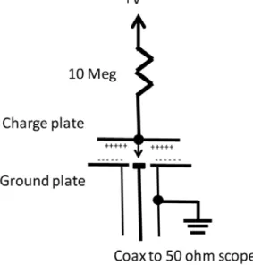
CDM Event Simulator (CDMES), 2012-13
10 Meg
Charge plate
Coax to 50 ohm scope
+V
Ground plate
+++++ +++++ - - -
14
第
18
屆台灣靜電放電防護技術暨可靠度技術研討會
2019 Taiwan ESD and Reliability Conference
Simco-ITW CDMES Model
10 Meg
Charge plate
Coax to 50 ohm scope +V
Ground plate
+++++ +++++ - - -
-Described in US Patent 9,671,448 (2017)
15
第
18
屆台灣靜電放電防護技術暨可靠度技術研討會
2019 Taiwan ESD and Reliability Conference
Field Detection with CDMES
16
第
18
屆台灣靜電放電防護技術暨可靠度技術研討會
2019 Taiwan ESD and Reliability Conference
Electric Dipole “equatorial” field
dl
dt
t
di
p
dl
t
i
p
s
sQ
s
I
dt
t
dQ
t
i
dl
t
Q
p
=
=
=
=
=
)
(
)
(
)
(
)
(
;
)
(
)
(
)
(
sin
=1 at
equator
In the s-domain, sin
=1:
Convert to practical units
c
r
s
s
dl
sr
s
I
s
E
=
+
+
=
(
1
),
4
)
(
)
(
3
2
2
0
s=
+j
+
+
=
2
2
3
0
]
[
]
[
]
[
4
sin
)
(
r
p
cr
p
r
c
p
t
E
17
第
18
屆台灣靜電放電防護技術暨可靠度技術研討會
2019 Taiwan ESD and Reliability Conference
Azimuthal magnetic field for pulsed e-dipole
3
2
( )
( )
(1
)
( )
(1
) sin
sin
4
4
cI s dl
I s dl
s
H
s
s
s
sr
r
+
=
+
=
• This expression would apply to a loop antenna used to detect
a pulsed electric dipole
• There’s a complementary expression for E
(s) for
magnetic
dipole, but remember e-dipole p(s) is I(s)/s times dl, while
magnetic dipole m(s) is I(s) times area.
• This will be important
later
, when E-field antenna detects
a pulsed magnetic dipole
18
第
18
屆台灣靜電放電防護技術暨可靠度技術研討會
2019 Taiwan ESD and Reliability Conference
Radiation zeros for pulsed e-dipole (from [4])
Dipole radiation
maps to pure
19
第
18
屆台灣靜電放電防護技術暨可靠度技術研討會
2019 Taiwan ESD and Reliability Conference
Dipole E-field, sin
=1
But we know that
0
2
1
)
(
LCs
RCs
CV
s
I
+
+
=
So
2
2
2
3
0
0
1
)
1
(
4
)
(
LCs
RCs
s
s
sr
dl
CV
s
E
+
+
+
+
=
Solve in time domain with
inverse Laplace Transform;
pole-zero expansion in
natural frequencies
s=
+j
20
第
18
屆台灣靜電放電防護技術暨可靠度技術研討會
2019 Taiwan ESD and Reliability Conference
What if poles & zeros cancelled at r=c
?
2
2
2
3
0
0
1
)
1
(
4
)
(
LCs
RCs
s
s
sr
dl
CV
s
E
+
+
+
+
=
2-pole response, balancing rad at 15 cm
-0.4 -0.2 0 0.2 0.4 0.6 0.8 1 1.2
0 500 1000 1500 2000 2500 3000 3500 4000 4500
21
第
18
屆台灣靜電放電防護技術暨可靠度技術研討會
2019 Taiwan ESD and Reliability Conference
Stationary sphere for pole-zero cancellation
22
第
18
屆台灣靜電放電防護技術暨可靠度技術研討會
2019 Taiwan ESD and Reliability Conference
Measured current (top) and antenna response
(bottom) to E-field at 15 cm, using artificial CDM
source; 2 nsec/division
p
23
第
18
屆台灣靜電放電防護技術暨可靠度技術研討會
2019 Taiwan ESD and Reliability Conference
Calculated current and field
Calculated CDM current
pulse, 1 nsec full scale.
E-field pulse E
at 15 cm
from CDM current
source; 1 nsec full scale.
24
第
18
屆台灣靜電放電防護技術暨可靠度技術研討會
2019 Taiwan ESD and Reliability Conference
Antenna Transfer Function
25
第
18
屆台灣靜電放電防護技術暨可靠度技術研討會
2019 Taiwan ESD and Reliability Conference
Transfer function in terms of initial
dipole source p
2
0
0
1
)
(
)
(
s
C
L
s
C
Z
s
C
Z
l
s
E
s
V
m
m
m
m
m
z
m
+
+
−
=
−
Calculated antenna response to E-field,15 cm from
CDM source, 1.5 nsec full scale
Predicted antenna signal. Good
agreement with measurement.
p
26
第
18
屆台灣靜電放電防護技術暨可靠度技術研討會
2019 Taiwan ESD and Reliability Conference
Adjust the current function just a little and…
0.5 1.0 1.5 2.0 0.5
1.0 1.5 2.0
arb
units
nanosec
current
0.5
1.0
1.5
2.0
30
20
10
10
20
30
arb
units
nanosec
Antenna
Antenna signal
is a
near-monocycle
p
27
第
18
屆台灣靜電放電防護技術暨可靠度技術研討會
2019 Taiwan ESD and Reliability Conference
Measured current (top) and antenna response
(bottom) to E-field at 15 cm, using artificial CDM
source; 2 nsec/division
p
15 cm
28
第
18
屆台灣靜電放電防護技術暨可靠度技術研討會
2019 Taiwan ESD and Reliability Conference
Measurement Uncertainties
•Dipole length dl is not precisely known for each zap
•Yet every field in the theory is proportional to dl
•Finite source size, spark timing, surrounding metal all affect fields
•Antenna properties, particularly effective capacitance
•Discharges can be fragmented (spark shower) and spread over short
times, meaning weaker device event but confusing signal
•But worst-case discharges are crisp dipole collapses
•We ultimately care about stress felt by the device, not the field. So we
must ask, how lousy can the radiation efficiency be?
•If it’s lousy enough, there’s a weak signal and a strong CDM event;
not good
第六屆台灣靜電放電防護技術研討會
2007 Taiwan ESD Conference
29
Keynote Speech (1) –
CDM Protection…
Correlation with CDM tester
--2007
Non-Socketed CDM Tester Used to Correlate EMI for
Various Device sizes, zap voltages, and antenna orientations
E
M
Aperture
Electric
Dipole
Discharge
Ball antenna
M
E
M
Aperture
Electric
Dipole
Discharge
Ball antenna
M
E
M
Aperture
Electric
Dipole
Discharge
Ball antenna
M
E
M
Aperture
Electric
Dipole
Discharge
Ball antenna
M
No E-field at
north pole; all
第六屆台灣靜電放電防護技術研討會
2007 Taiwan ESD Conference
30
Keynote Speech (1) –
CDM Protection…
EMI from non-socketed CDM tester
6” Above Aperture V
p-p
= 3.5V
12” Above Aperture V
p-p
= 882mV
1GHz Center Frequency, 100MHz per Division
Inverse square law affirmed (V
p-p
) for magnetic dipole
31
第
18
屆台灣靜電放電防護技術暨可靠度技術研討會
2019 Taiwan ESD and Reliability Conference
Artificial antenna pulses
TLP-based setup with two
quarter-wave 3 dB couplers, aimed at
producing a monocycle pulse.
Monocycle pulse output at 50V line
charge, 2.5 nsec/division. Vp-p=5.52 V
32
第
18
屆台灣靜電放電防護技術暨可靠度技術研討會
2019 Taiwan ESD and Reliability Conference
TLP in
Coupler 1
Coupler 2
OUT, to scope
Coupler 1 to
Coupler 2
33
第
18
屆台灣靜電放電防護技術暨可靠度技術研討會
2019 Taiwan ESD and Reliability Conference
Approximate solution, monocycle
.
3
1
)
(
)
(
2
02
2
01
'
2
'
1
02
01
2
'
2
02
'
1
01
'
2
'
1
2
02
01
2
1
1
+
+
+
+
+
+
=
t
t
k
k
t
t
s
k
t
k
t
s
k
k
s
t
t
k
k
s
V
s
V
m
i.e., close to a
double derivative
•Predicted monocycle signal using 2-pole approximations
•5 nsec full scale
•Peak heights, ratios, pulse shape and time scale are all close to measured data.
•See 2012, 2013 references
34
第
18
屆台灣靜電放電防護技術暨可靠度技術研討會
2019 Taiwan ESD and Reliability Conference
Calibration Example
Simco-ITW MiniPulse is detector. Must have z-mismatch
to simulate actual antenna (a near-open circuit). Input of
35
第
18
屆台灣靜電放電防護技術暨可靠度技術研討會
2019 Taiwan ESD and Reliability Conference
Monocycle pulse (left, 175 mV=Vp-p) and its
reflection from ESD event detector (right, 112 mV)
36
第
18
屆台灣靜電放電防護技術暨可靠度技術研討會
2019 Taiwan ESD and Reliability Conference
TLP step
50
C
90
ISO
IN
ISO 90
0
Coupler 1
all 50
0
IN
Coupler 2
MiniPulse
50
scope
150 cm
cable
450
Pickoff tee
Monocycle pulse
generator for hi-Z pulse
and setup for calibration
of ESD detector
37
第
18
屆台灣靜電放電防護技術暨可靠度技術研討會
2019 Taiwan ESD and Reliability Conference
MiniPulse calibration
Monocycle pulse peak-to-peak voltage (Vp-p)
magnitude vs. threshold setting of MiniPulse event
detector, semi-log plot. Excellent agreement with
exponential fit (422 mV/decade).
Vp-p sensitive,
as hoped. Log
amp in MiniPulse
38
第
18
屆台灣靜電放電防護技術暨可靠度技術研討會
2019 Taiwan ESD and Reliability Conference
Comments on First Six Years of Usage
•Heavy use of CDMES for
in situ
electrostatic event creation
•MiniPulse is a compact substitute for a scope but improved versions
are possible
•Hi-pass input filter and log amp are its most important features at
present
•Field-detection tools are used for troubleshooting and maintenance,
more than continuous
in situ
monitoring of process
•Managers will decide usage level, based on cost
•Consider in context of history of ESD-related factory tools, e.g.,
GPS-like location of ESD event (1990s), developed but not
Tim Maloney, 2/09
Intel Corp.
39
CDM Target for TDT
TLP Transients
notes for WG 5.5
Tim Maloney
February, 2009
Next section: CDM testing without the air spark
Tim Maloney, 2/09
Intel Corp.
40
Concept: New TDT Target
DUT
Current and
Voltage Probes
Transmission Line
Switch
Pulse
Attenuator
Delay Line
HV Power
Supply
10-100M
50
Oscilloscope
Measurement
Attenuator
Recommended Pulse Attenuation: 6dB to 20dB
Recommended Measurement Attenuation: 6dB to 20dB
Figure 5: Time Domain Transmission (TDT) VF-TLP
![Fig. 1. From [9]; setup of antenna and field detector near a manufacturing station that may cause CDM events](https://thumb-us.123doks.com/thumbv2/123dok_us/8195558.2172648/1.892.469.761.391.560/setup-antenna-field-detector-manufacturing-station-cause-events.webp)