Objective FP7-ICT-2009-5-257448/D-5.2
Future Networks
Project 257448
“SAIL – Scalable and Adaptable Internet Solutions”
D-5.2
(D-D.1) Cloud Network
Architecture Description
Date of preparation: 11-07-31 Revision: 1.0
Start date of Project: 10-08-01 Duration: 13-01-31
Project Coordinator: Thomas Edwall Ericsson AB
Document Properties
Document Number: D-D.1
Document Title:
Cloud Networking Architecture Description
Document Responsible: Paul Murray (HP)
Document Editor: Paul Murray (HP)
Authors:
Bob Melander (EAB) Victor Souza (EAB)
Volker Fusenig (Fraunhofer) Ayush Sharma (Fraunhofer)
Mickael Meulle (FT Orange) Dev Audsin (HP)
Paul Murray (HP) Suksant Sae Lor (HP)
Luis Vaquero (HP) Thomas Begin (INRIA)
Paulo Gon¸calves (INRIA) Guilherme Koslovski (INRIA)
Shubhabrata Roy (INRIA) Wajdi Louati (IT)
Marouen Mechtri (IT) Houssem Medhioub (IT)
Djamal Zeghlache (IT) Markus Hidell (KTH)
Rolf Stadler (KTH) Peter Sjodin (KTH)
Daniel Turull (KTH) Fetahi Wuhib (KTH)
Pascale Vicat-Blanc (Lyatiss) Dominique Dudkowski (NEC)
Jorge Carapinha (PTIN) Marcio Melo (PTIN)
Joao Soares (PTIN) Romeu Monteiro (PTIN)
Daniel Gillblad (SICS) Rebecca Steinert (SICS)
Bj¨orn Bjurling (SICS) Bj¨orn Levin (SICS)
Avi Miron (Technion) Pedro Aranda (TID)
Ibrahim Menem (TID) Target Dissemination Level: PU
Status of the Document: Final
Version: 1.0
Production Properties:
Reviewers: Bengt Ahlgren (SICS), Hannu Flinck (NSN)
Document History:
Revision Date Issued by Description
1.0 2011-07-31 Paul Murray Final version
Disclaimer:
This document has been produced in the context of the SAIL Project. The research leading to these results has received funding from the European Community’s Seventh Framework Programme (FP7/2010–2013) under grant agreement n◦ 257448.
All information in this document is provided “as is” and no guarantee or warranty is given that the information is fit for any particular purpose. The user thereof uses the information at its sole risk and liability.
For the avoidance of all doubts, the European Commission has no liability in respect of this document, which is merely representing the authors view.
Abstract:
This document describes the first complete version of the Cloud Networking architecture pro-posed by SAIL WPD. The concept of cloud networking is introduced in a multi-administrative domain scenario, where network and data centre domains exist and must interact through de-fined interfaces to provide a service to cloud customers. Cloud networking builds upon two main concepts. The first is integration of the networking resources onto existing data centre based cloud infrastructures. The network resource is represented by defined flash network slices which are dynamic elastic network connections. The second concept is the deployment of computing and storage resources distributed in the network to allow for better end-user experience and lower the dependency on network capacity. The architecture introduces administrative domains, interfaces, logical functions, and a description of inter-domain interactions to provide complete end-to-end services. Management algorithms for user goal translation, fault and resource man-agement are presented, including early results from experimentation and simulations. Security goals are outlined along with a description of proposed approach to security goals and policy based access control. This architecture will be further refined and modified according to results from implementation of a prototype and experimentation.
Keywords:
cloud computing, cloud networking, network virtualisation, infrastructure as a service, cross-domain vir-tual infrastructure, resource management, cloud network security
Contents
List of Figures v List of Tables ix List of Acronyms x 1 Introduction 1 1.1 Architectural Constraints . . . 1 1.2 Business Justification . . . 2 1.3 Document Outline . . . 32 High Level Architecture 5 2.1 Three Layer Model . . . 5
2.1.1 Resources . . . 5
2.1.2 Single-Domain Infrastructure . . . 6
2.1.3 Cross-Domain Infrastructure . . . 7
2.2 Flash Network Slice . . . 7
2.3 Roles . . . 8
2.4 Interfaces . . . 10
2.4.1 Resource Administration . . . 10
2.4.2 Distributed Control Plane . . . 12
2.4.3 Infrastructure Service . . . 12
2.5 Service Request Management . . . 13
3 Data Model 15 3.1 Data Model Principles . . . 15
3.1.1 Delegation . . . 15
3.1.2 Model Transformation . . . 15
3.2 Basic Model Concept . . . 18
3.2.1 A Possible Embodiment of the Data Model . . . 19
3.2.2 Unique Universal Naming in a Distributed Cloud . . . 19
3.3 Network Model . . . 21
3.3.1 Single Router (Node) Abstraction . . . 22
3.3.2 Goal Translation and Data Model Refinement Synchronisation . . . 23
4 Control Interactions 27 4.1 Principles of Infrastructure Control . . . 27
4.2 Control Interactions . . . 27
4.2.1 Delegation Based Control . . . 28
4.2.2 Distributed Coordination . . . 28
4.2.3 Reference Resolution . . . 29
4.3 Interface Design . . . 29
4.3.2 Distributed Coordination . . . 31
4.4 Interface Standardisation . . . 32
4.5 Conclusion and further steps . . . 36
5 Cloud Network Management 37 5.1 Management Concepts . . . 37
5.2 Management Architecture . . . 38
5.2.1 Goal Translation Function . . . 39
5.2.2 Fault Management Function . . . 40
5.2.3 Resource Management Function . . . 41
5.2.4 Management Function Interfaces . . . 42
5.2.5 Management Processes . . . 42
5.2.6 Information Exchange and Workflows . . . 44
5.3 Initial Approaches . . . 46
5.3.1 Goal Translation and Monitoring of High-Level Objectives . . . 46
5.3.2 High-Level Specification . . . 47
5.3.3 Fault Detection in Virtualised Systems . . . 48
5.3.4 Scalable Resource Allocation under Management Objectives . . . 49
5.3.5 Distributed Oblivious Load Balancing in Cloud Computing . . . 50
5.3.6 Live Migration of Services in the Cloud . . . 51
5.3.7 Predicting and Modeling Virtual Infrastructures . . . 52
5.3.8 Resource Discovery, Embedding and Reconfiguration in CloNe . . . 53
5.4 Conclusion and Further Steps for Management . . . 54
6 Network View 55 6.1 Mapping to Virtual Private Networks . . . 55
6.1.1 Introduction . . . 55
6.1.2 VPNs providing access to Clouds . . . 56
6.1.3 Challenges to use VPNs in a Cloud environment . . . 57
6.1.4 A new VPN abstraction . . . 58
6.2 Mapping to Flow-Based Networks . . . 59
6.2.1 OpenFlow Background . . . 60
6.2.2 Intermediate Virtualisation Controller . . . 61
6.2.3 Dedicated Controllers . . . 63
6.3 Mapping to Virtual Networks . . . 64
6.3.1 Background . . . 64
6.3.2 Implementation . . . 65
6.4 Network View Summary . . . 65
7 Security Architecture 69 7.1 Security Analysis and Requirements . . . 69
7.1.1 Security Goals . . . 69
7.1.2 Attacker Model . . . 70
7.1.3 Resulting Security Challenges . . . 70
7.2 Security Methodology . . . 71
7.2.1 Obtaining Security Goals . . . 72
7.2.2 Security Goal Translation . . . 73
7.2.3 Auditing Mechanism . . . 74
7.3 Security Parameters . . . 74
7.4.1 Administrator . . . 75
7.4.2 Infrastructure Service User . . . 75
7.5 Relation to Technical Architecture . . . 76
7.6 Security Goal Translation Example . . . 77
7.7 Access Control Policy . . . 79
7.8 Conclusion and Further Steps for Security . . . 79
8 Relation to Use Cases 81 8.1 Video on Demand Use Case . . . 81
8.2 Enterprise Use Case . . . 82
9 Related Work 85 10 Conclusions and Future Work 91 10.1 Future Work . . . 91
A Management Algorithm Results 93 A.1 Goal Translation and Monitoring of High-Level Objectives . . . 93
A.2 Fault Detection in Virtualised Systems . . . 94
A.3 Predicting and Modelling Virtual Infrastructures: initial results . . . 95
A.4 Mapping of Virtual Networks with Cloud Resources . . . 97
List of Figures
2.1 Three Layer Model . . . 5
2.2 Roles in a Simple Arrangement . . . 8
2.3 Roles in a Hierarchical Arrangement . . . 9
2.4 Roles in a Peering Arrangement . . . 10
2.5 Interfaces . . . 11
3.1 A Possible Approach for Information Hiding and Goal Translation. . . 17
3.2 A Simple Data Model. . . 18
3.3 Example of Elements Considered in a Virtual Infrastructure + Virtual Topology Description Data Model. Taken fromhttp://vxdlforum.org . . . 20
3.4 Two Possible Approaches for Distributed and Uncoordinated Naming. . . 21
3.5 Single Router (Node) View of the Network of a Domain. . . 23
3.6 VXDL example of goal description. . . 25
4.1 Two Aspects of Control Interaction Across Infrastructure Services . . . 28
4.2 Control interactions across domains . . . 30
4.3 Hierarchical control interactions . . . 31
4.4 Peer control interactions . . . 32
4.5 OCCI Protocol and API placement in a provider’s architecture from [1] . . . 33
4.6 UML diagram of the OCCI Core and Infrastructure . . . 33
4.7 OCNI - An OCCI extension for cloud networking . . . 34
4.8 CloNe proposal for an OCNI extension of the OCCI framework . . . 35
5.1 Conceptual overview of the management functions and the functional blocks. . . 39
5.2 Example of management interfaces. . . 42
5.3 Overview of processes for management of flash network slices. . . 43
5.4 Principal communication between management functions. . . 45
6.1 Basic VPN types: CPE-based vs. Network-based . . . 56
6.2 Cloudbursting scenario . . . 58
6.3 Resource migration scenario . . . 59
6.4 FNS mapping to OpenFlow . . . 60
6.5 Slicing using FlowVisor . . . 62
6.6 OpenFlow view . . . 63
6.7 Network Virtualisation technology overview within 4WARD [2] . . . 66
7.1 Security mechanisms . . . 72
7.2 Security goal translation . . . 73
7.3 Three layer model goals . . . 76
7.4 Delegation of security goals . . . 76
7.5 Hierarchical arrangement of goal translation . . . 78
8.2 Video on Demand Use with an example of the evolution of aggregate viewers for five
different videos introduced in the server at the same time . . . 83
8.3 Enterprise Use Case . . . 84
A.1 Average overhead for an increasing number of nodes, with theoretical path lengths
calculated from the entire graph (T1) and as a sum of individual layers (T2). . . 95
A.2 Average overhead for an increasing number of layers. . . 95
A.3 An example of the evolution of viewers with changing value ofβ(Popularity) for one
video. . . 96
A.4 An example of the evolution of viewers with changing value ofβ (Popularity) for the
aggregate of five different videos. . . 97
A.5 Acceptance rate (number of accepted requests / number of total requests) varying the number of physical subtract nodes. . . 98 A.6 Acceptance rate (number of accepted requests / number of total requests) varying the
List of Tables
List of Acronyms
4WARD Architecture and Design for the Future Internet
API Application Programming Interface
BGP Border Gateway Protocol
CDMI Cloud Data Management Interface
CloNe Cloud Networking
DCP Distributed Control Plane
DoS Denial of Service
ECC Elliptic Curve Cryptography
ETSI European Telecommunications Standards Institute
FNS Flash Network Slice
IaaS Infrastructure as a Service
IP Internet Protocol
ISP Internet Service Provider
MOM Message Oriented Middleware
MPLS Multiprotocol Label Switching
NetInf Network of Information
NIC Network Interface Card
OCCI Open Cloud Computing Interface
OCNI Open Cloud Networking Interface
OConS Open Connectivity Services
OGF Open Grid Forum
PCI DSS Payment Card Industry Data Security Standard
PKI Public Key Infrastructure
QoE Quality of Experience
QoS Quality of Service
S3 Simple Storage Service
SAIL Scalable Adaptive Internet Layering System
SDLC Software Development Life Cycle
SLA Service Level Agreement
SNIA Storage Networking Industry Association
SOA Service Oriented Architecture
URI Universal Resource Identifier
UUID Universally Unique Identifier
VLAN Virtual Local Area Network
VM Virtual Machine
VoD Video on Demand
VPN Virtual Private Network
1 Introduction
Cloud computing is set to form the bedrock of a fundamental change in the way enterprise IT and consumer services are implemented and delivered. Already cloud computing providers are offering infrastructure-as-a-service, implementing virtualised compute, storage and network as an environment in which to deploy and run applications and services; and new enterprise IT and consumer services implemented in these environments are appearing every day. Paid for according to use, such environments afford service providers the ability to scale far beyond the limits of investment justified by fluctuating and uncertain demand and without impacting user quality of experience.
Today Infrastructure as a Service (IaaS) is an immature and proprietary technology largely focused on data centre provision of compute and storage facilities. The networking aspect of infras-tructure as a service and the lack of of network support beyond the data centre are a limiting factor preventing applications and communication services that are sensitive to network characteristics from adopting this approach. The related infrastructure service interfaces need to be standardised in order to facilitate wide and smooth deployment and to provide a consistent access by users to any cloud provider.
The subject of this document is an architecture for Cloud Networking (CloNe). The aim of CloNe is to complete the cloud computing picture by addressing the networking aspect. We introduce
the concept of a flash network slice, a network resource that can be provisioned and dimensioned
on a time scale comparable to existing compute and storage resources. Flash network slices can be used to construct and connect virtual infrastructures spanning providers, creating environments in which to deploy, scale and distribute services across data centres, throughout networks, to end users across the globe.
1.1 Architectural Constraints
The CloNe architecture is grounded in a few basic constraints derived from the nature of networking and the current trend in cloud computing. These are described as follows:
• Can be realised on currently deployed network technologies – in recognition that it is not viable to take a revolutionary approach to changing the way existing deployed networks operate we wish to derive an architecture that can be used in existing deployments.
• Can be realised on network technologies that are expected in the future– we expect our architecture to encompass new networking technologies that more effectively support dynamic configuration of virtual network resources and to provide a migration path to the adoption of such technologies.
• Compatible with current approaches to cloud computing – IaaS offerings already have emerging standards for management of computing and storage resources. To embrace infrastructure as a service as a way to provision a combined networking and computing infrastructure we need to cooperate with these existing components.
• Can be realised across multiple administrative domains– we expect network providers to interoperate with each other and with privately owned infrastructures and end users, such
that CloNe infrastructures can be constructed from virtual resources realised in different administrative domains, with technological and operational independence.
1.2 Business Justification
The deployment of infrastructure and applications in a cloud is today largely motivated by cost reduction. Cloud computing features on demand provisioning of resources without upfront commit-ments; elastic reconfiguration of those resources and pay-per-use business model. Any applications that show a high degree of demand fluctuation will likely yield lower cost when deployed in a cloud, since provisioning is not done for peak demand. Cloud computing can significantly reduce capi-tal expenditure, leaving customer only with the costs of operating the IT infrastructure of their businesses.
Cloud networking proposes the deployment of in network servers (cloud servers) in order to improve end-user experience. In that scenario, servers can be placed close to end-users allowing for lower latency and packet loss ratio avoiding congested links when accessing that server. These servers should be placed in multiple places throughout the network. The number of servers in each one of these of points of presence will be much smaller than a traditional data centre cloud; however, they will be serving a much smaller part of the users as well. Applications that demand interactivity will benefit of such deployment. We can this type of deployment a distributed cloud. This scenario does not substitute the need for traditional data centre deployed clouds, where massive amounts of servers can be provisioned. The business case of such a distributed cloud leverages upon the enhanced end-user experience for applications where the data centres may be too far away. It is envisioned that a pay-per-use model could be used as well. Pricing may be differentiated though.
The second important aspect is the provisioning of elastic networking connectivity. A possible business model for the elastic networking is a pure extension of the cloud computing business model. Cost reduction will happen since customer will be able to adapt the network service according to the application demand. During low usage periods (e.g., evenings) the customer should be able to dimension its service accordingly and pay only for the needed network capacity.
Moreover, cloud networking goes beyond the above to propose new business cases where different providers cooperate to deploy a given application. The cooperation is made on the basis of mutual deployment of different parts of the customer services. An infrastructure provider may not be able to fully satisfy a user request. It may, however, satisfy part of it and delegate the deployment of the rest to another infrastructure provider. The user does not need to be aware of that, as long as all of its requirements are satisfied. Those requirements may be related to legal aspects, e.g., deployment of application under a certain jurisdiction, or to security level associated to data storage, amongst others.
The concept of delegation has important implications on the business case of the whole solution. First of all, a business to business interface amongst infrastructure providers needs to be estab-lished. Infrastructure providers should be able to automatically negotiate and charge each other for provided services. Second, it allows the user to deploy its applications across many providers through one business relationship. Essentially, cloud customers can continue to use their existing business relationships and benefit from the cross provider infrastructure deployment enabled by cloud networking.
Delegation allows for CloNe providers to deploy fewer resources since each of them can rely on remote resources to fulfil its peak demand. Different CloNe providers experience peak demand at different times and delegations may mean a cost-saving opportunity. Clearly, each CloNe provider will have to decide upon the amount of infrastructure to be deployed, considering cost, and the risk of not having other providers to supply resources during periods of high demand.
Finally, delegation will enable the creation of a marketplace where infrastructure providers can negotiate resources amongst each other. Infrastructure providers may decide to establish static sharing agreements. Dynamic agreements will however foster competition and allow for a greater degree of flexibility when deploying cloud services.
1.3 Document Outline
The approach of this document is to describe the architecture of an infrastructure service from a high level of abstraction and then demonstrate how components of the architecture relate to real technologies in order to validate that it conforms to the basic constraints described above.
The high level architecture is presented in Section 2, including a framework for characterising virtual infrastructure, the flash network slice infrastructure resource, the roles involved in interac-tion with an infrastructure service, interfaces relevant to an infrastructure service, and management functions of an infrastructure service. The delegation concept is introduced in this section.
Section 3 describes the characteristics of a data model for virtual infrastructure including the flash network slice.
Section 4 characterises the information flows of control aspects of the architecture and presents an example design for an infrastructure service that supports control interaction across multiple administrative domains.
Section 5 describes a framework of core management functions that compose an infrastructure service and demonstrates how management algorithms can be implemented in that framework.
Section 6 focuses on realisation of the flash network slice resource in various technologies, from those commonly deployed today to those that may be deployed in the future.
Section 7 describes a security architecture based on accreditation and compliance that can be used in conjunction with the technical architecture.
Section 8 describes how the use cases described in [3] can be implemented in the CloNe archi-tecture.
Section 9 relates our work to work carried out in other projects and Section 10 summaries the current state of CloNe and identifies future work.
CloNe is one of three technical work packages of the Scalable Adaptive Internet Layering System (SAIL) project; the others are Network of Information (NetInf) and Open Connectivity Services (OConS). Each work package describes an architecture for its respective system and the relationship among these is covered in [4].
The SAIL project addresses four themes across the work packages: security,management,
inter-provider issues, and prototyping. These themes are addressed throughout the CloNe architecture. The security theme is addressed in the security architecture described in Section 7 and the au-thentication interfaces outlined in the high level architecture in Section 2 and the control view in Section 4. Management is addressed in the infrastructure service functions of the high level archi-tecture and in Section 5. Inter-provider issues relate to the cross-domain aspects of the archiarchi-tecture including control in Section 4 and reference resolution in Section 3. Prototyping activities are at an early stage in CloNe and are beyond the scope of this document.
2 High Level Architecture
The CloNe high level architecture consists of four parts: the three layer model; a set of roles; a set
of interfaces by which the roles interact; and a set of management functions in which these roles participate. The three layer model is a framework for characterising virtual infrastructure relative to three different view-points. The roles, interfaces and management functions are characterised by reference to the three layer model. This section describes each of these parts. In addition the Flash Network Slice (FNS), a new component of virtual infrastructures introduced by CloNe, is defined in the context of the architecture.
2.1 Three Layer Model
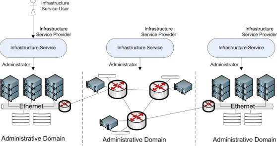
Figure 2.1: Three Layer Model
Figure 2.1 is a visual representation of the view-points used to characterise the components of the CloNe architecture. An administrative domain is a collection of physical or virtual equipment that is under the management of an administrative authority. As Figure 2.1 shows, examples of administrative domains in the context of CloNe are wide area networks and data centres. Virtual infrastructure is within an administrative domains and a single infrastructure may span multiple domains. Administrative domains are depicted at the bottom of Figure 2.1. The three layers above the administrative domains represent three different views of virtual infrastructure. The three
layers include resource, single-domain infrastructure, and cross-domain infrastructure. Later we
describe the roles, interfaces and functions in relation to each of these views.
The way authority is segregated over administrative domains influences the management of virtual infrastructure and the construction of the three layer model.
2.1.1 Resources
A virtual resource is an abstract representation of a component of a virtual infrastructure such as a virtual machine or a volume on a block device. A virtual resource resides within the boundaries of a single administrative domain. The resource layer includes compute resources, storage resources, and network resources as virtual entities that are generally managed by different sub-systems. Resources can be identified (or named), they have certain properties and status and may have links to other resources.
Properties, status and links are not the same. A property is externally determined (i.e. it is an attribute set from the outside such as memory size for a virtual machine or address space for a subnet), a status is internally determined (i.e. it reflects a condition of the virtual resource: a life cycle stage, an error condition or an attribute derived from its circumstance), a link describes a relationship to another virtual resource and is interpreted relative to the other resource.
It is relevant to notice that CloNe proposes resources to be at the bottom of both data centres and operators networks. CloNe proposes computing and storage resources to be deployed in the operators networks (e.g., wide area networks). Similar resources (e.g., a virtual machine) may have a different property set depending on the administrative domain where they reside. For example, the network location of a virtual machine is a property that is relevant in the wide area network but not as much in the data centre. Regardless, from a management perspective, both are simply resources.
A virtual resource can be created, managed and destroyed. These control actions are typically performed by a subsystem such as the management interface on a virtual machine hypervisor or a storage device manager such as a storage array control system. The act of creating a virtual resource will typically consume some physical resource (e.g. disk space) or a logical resource (e.g. an Internet Protocol (IP) address or bandwidth). Destroying a virtual resource will free these physical or logical resources.
Virtual resources are often connected to other virtual resources: a virtual machine may be connected to a virtual network or a storage device, establishing a relationship. The nature of this relationship can determine if the virtual resource can be correctly established in its own right or if it depends on the existence of the related virtual resource, its properties or its status. We assume interaction between the control mechanisms of different virtual resources within a single administrative domain where it is necessary to interpret the condition of a link. As an example a virtual machine manager may have to interact with a storage device to connect a virtual machine to a network attached volume. It may also communicate with a network management interface to add a virtual machine to a virtual network.
A virtual resource can be managed by a single administrative domain, but may have links with virtual resources in other administrative domains. This is particularly true of network connectivity as it is the means of interacting beyond the boundary of one provider. We assume interaction between control mechanisms of different resources in different administrative domains where it is necessary to interpret the condition of a link or to establish a link.
2.1.2 Single-Domain Infrastructure
We consider a single-domain infrastructure to be a number of virtual resources managed collectively within a single administrative domain. The links among these virtual resources determine the topology of the infrastructure and constrain their combined management behaviour.
A single-domain infrastructure is managed by a single administrative authority that has manage-ment rights over the underlying equipmanage-ment and virtualisation technology. As a consequence, within a single domain the administrative authority has full knowledge about the available resources and virtualisation capabilities at any time. A single-domain infrastructure can be created, updated, managed and destroyed.
At this layer the mapping between the single-domain infrastructure and the underlying equipment can be determined. This mapping can take into account group allocation (all or nothing allocation of a collection of virtual resources) and optimal placement (relative placement of virtual resources or use of underlying infrastructure). For example a Virtual Machine (VM) could be placed in a location with optimal network performance relative to a given end user.
Some technology selections can be made at this layer. A virtual machine could be executed on a choice of different servers with different memory sizes or chip sets giving different performance
trade-offs; a disk volume could be placed on local storage or network attached storage; a network link could be mapped to an isolated Virtual Private Network (VPN) tunnel or an open shared network.
Optimal placement and technology selections will depend for the most part on private policies of the administrative authority for the domain. However, the properties of the virtual resources and their links and the properties of the virtual infrastructure as a collection will influence the choices, in some cases dictating minimal requirements for the virtual infrastructure.
2.1.3 Cross-Domain Infrastructure
We consider a cross-domain infrastructure to be a number of virtual resources managed collectively across multiple administrative domains. A cross-domain infrastructure can be partitioned into mul-tiple single-domain infrastructures. A single-domain infrastructure may contain virtual resources that have links with virtual resources in other single-domain infrastructures, thus connecting the virtual infrastructures and determining the topology of the cross-domain infrastructure.
A cross-domain infrastructure is managed by multiple administrative authorities. In contrast to a single-domain infrastructure, the state of underlying equipment and virtualisation capabilities are likely not fully shared beyond domain boundaries. In this type of infrastructure, specific interfaces via which resource virtualisation is negotiated are necessary. Via such interfaces, the authorities of administrative domains may exchange limited information that they are willing to share about their domain in order to facilitate the optimization of cross-domain virtualisation. A cross-domain infrastructure can be created, updated, managed and destroyed.
Decomposing the requested virtual infrastructure into administrative domains can be performed at this level based on the capabilities of the administrative domains and their interconnection. Properties and links of the virtual resources and properties of the requested virtual infrastructure as a collection will obviously influence the decomposition process.
2.2 Flash Network Slice
The FNS is a new resource that is introduced by CloNe. The purpose of a FNS is to more fully address network capabilities in the IaaS paradigm according to CloNe requirements. A FNS has the following properties:
• Network resource: it is a resource providing network communication capability.
• Links: it can be attached to other resources by links, for example a VM may be attached to a FNS or two FNSs may be attached to each other. A link may span administrative domains. • Space of interconnected links: it implements message forwarding between links.
• Quality of service: it has quality of service properties associated with its communication capability between links.
• Single administrative domain: it is constructed and managed within a single administra-tive domain (this conforms to the definition of a resource given above).
• Set up time: it is established automatically and in a time frame comparable with existing virtual infrastructure resources such as VMs.
The FNS provides a communication capability between resources that are linked to it. Where two FNSs are linked to each other they provide a communication capability that spans the two slices. As links between FNSs are allowed to span domains, this provides a communication capability that is fundamental to the establishment of infrastructures across domains.
2.3 Roles
The use cases that guide the definition of the CloNe architecture are described in [3]. Here we define the common set of roles that are representative of those found in the use cases:
• Administrator has administrative authority over underlying virtual or physical equipment (the administrative domain) used to implement resources. The administrator uses manage-ment systems to configure and manage resources within the administrative domain.
• Infrastructure Service Useraccesses an infrastructure service in order to obtain, examine, modify and destroy resources.
• Infrastructure Service Provider offers an infrastructure service that may be used by an infrastructure service user to obtain, examine, modify and destroy resources.
The roles are acted out by various organisations involved in specific use cases. Typically the use cases involve data centre operators, network operators or agents reselling access to virtual resources to implement an infrastructure service. Use cases involve a user that obtains access to the infrastructure provided by the infrastructure service: such as an enterprise, an application service provider or a communication service provider. Although most scenarios involve a user of the application or communication service created within a virtual infrastructure, these types of user do not interact with an infrastructure service in that capacity. Roles may be added to represent these actors in specific use cases, and other actors as required, but they do not form part of the common set we describe in the high level architecture.
Figure 2.2: Roles in a Simple Arrangement
Figure 2.2 depicts a simple arrangement of infrastructure services to demonstrate where these
roles fit in an infrastructure service. The infrastructure services in the figure have theadministrator
role, meaning they have access to their own administrative domain and can manage individual virtual resources directly. The administrator role performs management of individual resources, placing it and the management systems it uses at the resource layer of the three layer model.
The infrastructure service in this figure also adopts the infrastructure service provider role to
resources within its own administrative domain, placing the infrastructure service provider and its service at the single-domain infrastructure layer of the three layer model in this case. The infrastructure service user at the top of the figure represents an organisation that makes use of virtual infrastructure. The interaction between the user and provider represents delegation; the provider is responsible for implementing and managing the virtual infrastructure on behalf of the user.
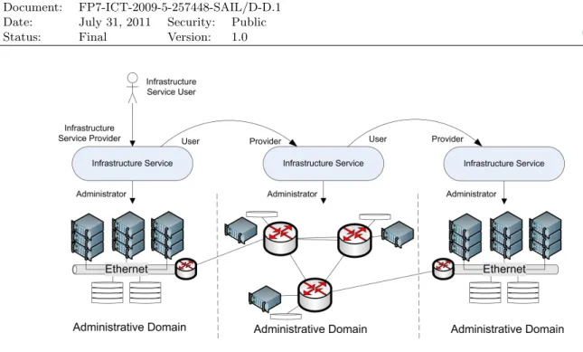
Figure 2.3: Roles in a Hierarchical Arrangement
Figure 2.3 depicts a more complex arrangement including a delegation hierarchy among infras-tructure services. In this case the topmost infrasinfras-tructure service adopts both the provider and user roles and is responsible for mapping the original user’s infrastructure requirements into parts that are implemented by the lower providers. This coordination of resources across multiple infrastruc-ture services is logically equivalent to a single instance of a service implementing the infrastrucinfrastruc-ture across domains (although the user may be aware of the final providers) and places the provider and service in this case at the cross-domain infrastructure layer. This service instance creates a delega-tion chain and it is the services with the administrator role that are responsible for implementing and managing the virtual infrastructure on behalf of the original user; the intermediary services track the delegation.
As is shown, the infrastructure services can be placed at either the single-domain or cross-domain infrastructure layer. The implication of each is that different types of behaviour are implemented depending on what roles they adopt. It is possible for an implementation of an infrastructure service to have both the infrastructure service user and administrator roles, implying it can both delegate and directly implement infrastructure, in which case it spans both layers. This can be used to implement a peering arrangement as shown in Figure 2.4.
Figure 2.4: Roles in a Peering Arrangement
2.4 Interfaces
Three interfaces are identified between the different roles of the architecture. They are theresource
administration interface, thedistributed control planeand theinfrastructure service interface. These are depicted in Figure 2.5 and described below.
2.4.1 Resource Administration
The resource administration interfaces correspond to the management functions that are used
by theadministratorrole to create, manage and destroy virtual resources within an administrative
domain. In general these interfaces are the management interfaces of some virtualisation technology such as the libvirt [5] virtual machine manager interface, a storage device controller or a network administration interface.
Basically, these resource administration interfaces are implementation specific. They must pro-vide information about the underlying infrastructure including the network topology and technolo-gies used, so that the administrator can make a decision on how to manage the resources and what information needs to be passed through these interfaces. Each interface (compute, storage or network) therefore, takes specific configuration details from an administrator in order to configure resources according to the infrastructure service user’s needs.
The following are examples of parameters and functions that could be present in these interfaces.
Compute Resource Interface
This interface provides technical capabilities similar to well-known interfaces like libvirt. At the same time it could be augmented with the ability to provide more advanced capabilities than pure virtual machine control (e.g. load balancing through virtual machine migration and distribution of compute tasks onto various machines). This interface provides access and ability to invoke a number of essential functions in handling resources such as:
Figure 2.5: Interfaces
• Compute service query and configuration to set performance target and express desired
com-pute service characteristics
• Selection of Software such as OS and execution environment
Storage Resource Interface
The storage service interface can very much rely on standards such as Cloud Data Management Interface (CDMI) and possibly on the de facto standard Amazon Simple Storage Service (S3) to provide access to virtual storage spaces as well as physical storage. Compatibility with such standard is essential as they are widely adopted in the cloud community. Additional needs emerge when network providers also provide storage within the network nodes such as caching and even storage of files, documents or multimedia files or data. These two types of interfaces need to blend and interoperate.
Network Resource Interface
Compute and Storage can be allocated and managed as cloud resources via well-defined web inter-faces and Application Programming Interinter-faces (APIs) such as those mentioned above. These kinds of interfaces and APIs are cloud computing and storage specific. What is missing today are the cloud networking interfaces and APIs that CloNe intends to add or introduce.
The objective is to define these missing interfaces and APIs so cloud networking can be achieved like traditional network configuration for Network Interface Cards (NICs), Virtual Local Area Networks (VLANs), OpenFlow, OpenvSwitch, Dynamic VPNs. This interface will highly depend on the capabilities of the underlying network and existing network management systems. It is expected that one should be able to configure parameters like bandwidth and jitter. Mobility may be supported, as well as fault monitoring, and redundancy. One could also set triggers for monitoring of SLA parameters.
The availability of specialised cloud networking interfaces and APIs will facilitate deployment, configuration, management and supervision of networks as an integrated part of private and hybrid cloud establishments.
2.4.2 Distributed Control Plane
The Distributed Control Plane (DCP) describes a category of protocols, interfaces and control
operations that enable two or moreinfrastructure service providers to interact and exchange
cross-administrative domain information. A more precise definition of the protocols and interfaces that constitute the DCP is the subject of future work. Here we give an informal description of some interactions that are expected to occur between providers.
• Reference resolution: the process of converting an abstract representation of remote in-formation to the actual inin-formation. As an example, if a network link is to be established, information about the remote end of the link may be required. That information may be represented by an abstract reference that can be resolved through the DCP to obtain the actual information. Reference resolution is described in more detail in Section 3.
• Notification: asynchronous information exchange, including publish-subscribe and
asyn-chronous callback protocols. This type of information exchange is used to decouple the
request for information from the response and is useful for distributed coordination. As an example, the establishment of a network link across domains may require cooperation between two providers that are operating asynchronously. One may request information from the other before the other is ready to supply the information. The notification service provides a means to transfer the information when it is available. As another example the information may rarely occur and is a trigger for processing (as opposed to being requested by processing). This is the case for fault-notification.
• Distributed information sharing: a distributed information service may provide a global view of infrastructure status information. The view may be maintained through a distributed protocol across providers allowing inspected by the providers.
The DCP operates at the cross-domain infrastructure layer and is generally concerned with distributed coordination and global information access. Communication between domains on DCP does not need to be synchronous. The specific protocols and interfaces used may depend on the specific relationship between domains and technology used. However, generic protocols may be employed to implement common coordination and communication services.
2.4.3 Infrastructure Service
The infrastructure service is a fundamental part of the CloNe architecture. The infrastructure service is the set of interfaces that enable the creation, monitoring and management of virtual
in-frastructures provided by theinfrastructure service providerrole and accessed by theinfrastructure
service userrole.
We assume that user requests to the infrastructure service will be performed using a high level description language. Those requests need to be broken down into low level actions inside the control plane for allocation of underlying resources within different domains. A high level description of the user requirements should yield a simpler way for the user to utilise resources that may be largely distributed. A good example of that is the location of the resources being utilised. The client interface should make it easy for the user to utilise highly distributed servers without having to bother about their specific topological location.
The objective is to allow the user to specify high level goals in the form of system service level agreements that will be automatically broken down into low level control actions. This language should define service goals that cross the boundaries between different cloud providers. It should also address functional and non-functional requirements of the users which may be constraints that end-user business processes may impose for example on process migration. The translation of the description language into control actions has to work in a distributed setting under the uncertainty that other parts of the cloud only partly fulfil their contracts.
For configuration and monitoring of services, cloud network management functions provide the functionality required to manage the cloud’s virtual resources and should also facilitate manage-ment of legacy networks. The functions can be viewed as higher-layer managemanage-ment entities that address cloud network specific requirements, utilizing available legacy management capabilities when necessary. For efficient and distributed cross-communication and information exchange be-tween management functions, collaboration is enabled through two interfaces - a controller interface and a collaboration interface (see Section 5.2).
The infrastructure service requires the use of well-defined security modules, in order to satisfy its security requirements, provided through user/operator/legal requirements, i.e., authentication, auditing, confidentiality, integrity and assurance, besides others. The security goal translation handles the realisation of security requirements on the underlying resources, with the help of ex-ternal modules, for example an auditing module and an access control policy module. This shall be covered in the Section 7.2.
2.5 Service Request Management
The cloud network management consists of three high-level management functions: goal
transla-tion (GT), transforming business, technical and security goals into resource configuration
objec-tives; fault management(FM), providing status updates of monitored resources, measurements and
models, as well as detecting faults, anomalies, and changes in performance; and resource
manage-ment (RM), responsible for provisioning, allocation, reconfiguration, optimisation of resources and
performance. Approaches and algorithms implementing management functionality are described in Section 5.
The management functions operate within infrastructure service providers and contribute in managing the administrative domain. Functional blocks within a management function implement a certain functionality using a set of management algorithms. The management algorithms need to be efficient with respect to their overhead, scalable with respect to the number of managed entities and adaptive as well as robust to all types of changes in the managed cloud. In order to achieve these properties, the algorithms operate in a decentralised manner, ensuring scalability, efficiency and reliability for the size of clouds envisioned. Decentralised collaboration between the management functions allows for administration, configuration and monitoring of individual FNSs as well as the cloud network. Through the DCP and management function interfaces (see section 2.4), the management functions exchange information for decentralised, adaptive and efficient management in both single-domains and cross-domains.
3 Data Model
CloNe adopts a model-based approach to describing and managing virtual infrastructure. The data model view describes the representation of virtual infrastructure and the format for its exchange among system components. A consistent representation is particularly important in this architec-ture as different system components are likely to be implemented by different parties, so a common understanding of the model and the data format used in exchange between system components is critical.
3.1 Data Model Principles
This section introduces how the description of the application, as provided by the user, is dealt with across the CloNe architecture and what are the governing principles that rule this process.
The architecture herein proposed is heavily dependent on adelegationprocess by which different
actors perform tasks that have been delegated to them by other actors in possession of a less accurate knowledge or lacking some required information to perform the task at hand. Obviously, the roles played by these actors can be combined so that a single individual/institution can play them as needed.
3.1.1 Delegation
Information describing a virtual infrastructure is passed between an infrastructure service user and an infrastructure service provider through the infrastructure service interface. The user describes the desired virtual infrastructure to the provider and the provider reports on its status to the user. Such descriptive information may be in an abstract form with the provider taking responsibility for determining implementation detail that is hidden from the user. This information exchange represents the act of delegation described in more detail in Section 4.
The presence of a common data model (semantically rich enough for expressing the required goals) and a common mechanism for labelling the entities in the model (so that information can be fed backwards once a delegated operation has been materialized) enables this information exchange. An infrastructure service can choose to repeat the delegation process, possibly across multiple other providers, until the required infrastructure is implemented within administrative domains. This repeated delegation presents a combination of model transformation and information hiding requirements for the data model that are inherent in the delegation approach.
3.1.2 Model Transformation
Once the user specifies a set of elements to be deployed and how they are connected, the infrastruc-ture service provider labels each element with a unique name. The infrastrucinfrastruc-ture service provider has some information that remains unknown for the user (e.g. underlying infrastructure details or topology of the virtual infrastructure, i.e. administrative domains and contract terms with each of these ones).
3.1.2.1 Abstraction Layers
This abstraction makes life for users easier, they delegate complex tasks to experts who can also ben-efit from economies of scale in their individual contracts with other infrastructure service providers (if they themselves delegate) or iron vendors (if they also play the role of administrators). For instance, infrastructure service providers will not provide complete visibility into the nature of the underlying physical infrastructure, its virtualisation, or other service implementation details. It will only make a selected set of service capabilities known to the user. We refer to this as information hiding.
On the other hand, users may not really care about the low level implementation and may specify their requests either in the form of a high level description (bubbles and links model) for their services to run, or may specify a more complex scenario in which they want to be in control of the whole networking topology connecting the VMs comprising their service in the cloud (possibly across federated data centres).
3.1.2.2 Model Refinement
This need for abstraction and hiding the underlying complexity to users is done at every level of the proposed architecture. Thus, the data model is a live element that evolves from a very general and vague description (users with little knowledge on the complexity underneath) to a detailed low level description of the components that are needed and their configuration.
The data model, thus, becomes the vehicle conveying the information that needs to be exported
at every level (the goals for deploying users’ requests and the monitoring data fed back to them)
and the one that needs to be refined or incorporated (matching in Figure 3.1) in the light of the newly available information when a lower level (in the chain of delegations) actor receives the data model. For instance, let us assume that an administrative domain has been delegated to deploy a VM from an independent infrastructure service provider. The infrastructure service provider lacks any knowledge on the network topology of the administrative domain or the specifics of racks, hypervisors, etc. At a higher level, an infrastructure service provider that delegates may hide details about the infrastructure service providers it uses (looking just as another normal infrastructure service provider to the user). These details contain, for instance, information such as price for deploying a VM, price per stored MB and QoS (e.g. time for a packet to traverse the diameter of
the network). This process of resource management (matching high level goals specified by a user
into something that can be materialized in the light of the, now, available information the user was lacking) and goal refinement (when the request is delegated to other providers of a domain, the goals need to be changed so that they reflect the available information) is essential in taking the user’s request to a concrete ground.
Infrastructure service providers may decide to deploy all their requests on a given domain as long as this complies with the users’ goals.
3.1.2.3 Model Splitting
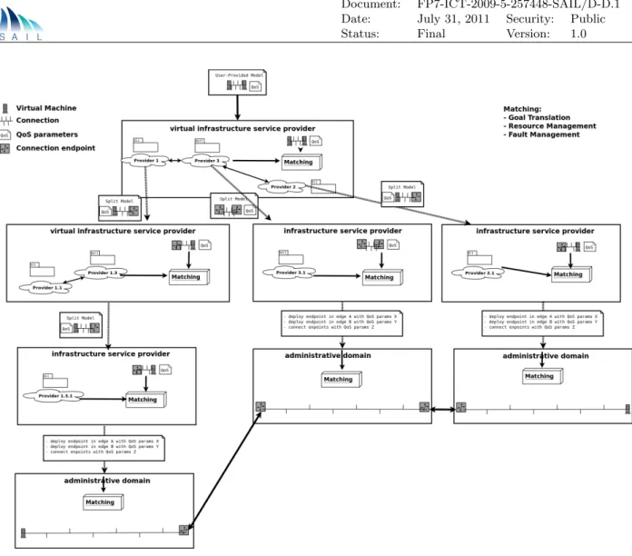
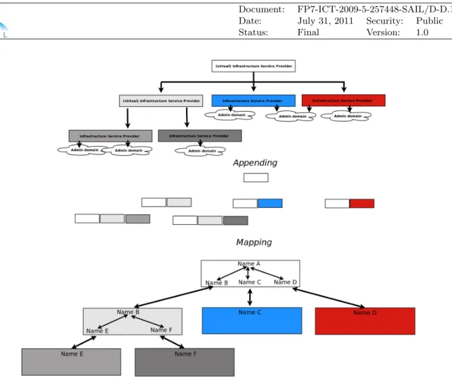
Figure 3.1 illustrates a case in which a network is required to span two domains that share a border in the form of connected edge nodes. These nodes need to be configured to interconnect the virtual networks in each domain. As is shown in Figure 3.1, the infrastructure service providers receive models of the network resources that they will implement in their respective domains. It is possible that the configuration details for the edge nodes cannot be completed without information from the neighbouring domain. For example, they may need to exchange ports, IP address or tags depending on the nature of the connection. They may also need to agree which edge nodes to use. It is likely that this is information that they will not be willing to share with anyone other than their neighbouring domain. This implies the information will be obtained by interaction between
Figure 3.1: A Possible Approach for Information Hiding and Goal Translation.
the lower service providers or in a protocol between the edge nodes - not by interaction with the higher service provider. It also implies that a model will contain information that relates to entities outside the model - such as the neighbouring service provider, a name to identify information held by the neighbouring service provider, or an abstract reference.
3.1.2.4 Dynamic Reference Resolution
Model refinement and splitting has a direct implication over the way things are referenced in the data model. For instance, when a user specifies she desires a VM in the UK and another one in France, she is (likely) indirectly generating a split of her request across multiple administrative domains. When her request is split and refined, the VM in the UK is referring to a VM in France whose final name (e.g. its host name) would only be known at deployment time.
The distributed naming expressed at the last paragraph of the section above (further detailed below in Section 3.2.2) is a way to keep these pointers consistent (a reference points to a unique resource or resource attribute). Once a VM has been allocated, its hostname becomes known and, therefore, the reference can be resolved by back propagating the reference to the required entities in the system (even the user if needed).
Generally speaking a reference will take the form of a protocol+container+resource. A universally accepted example is the Universal Resource Identifier (URI):
Also, the naming scheme under development in SAIL’s NetInf work package is being considered for this crucial task.
This simple example is revealing the need for aligning naming and reference resolution so that once a reference is dynamically resolved, it gets delivered back to the interested parties (e.g. VM in the UK gets to know the host name for the VM in the UK). Of course, these are more related to implementation matters than to an architectural definition, but they are issues worth pointing out when tackling the design of the system sketched by this architectural document.
3.2 Basic Model Concept
The architectural model should have a formalised representation of the previous description on how the elements in the model will be dealt with. Thus, a first step towards a valid data model is to have a clear view of the entities in the system and how they are related to each other. The main two elements in the system are, therefore, the resources that need to be deployed or configured at each level and the relationships, links among them.
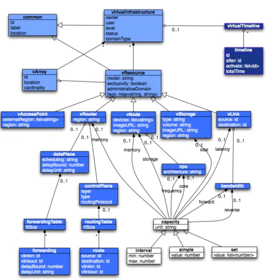
The basic abstractions included in these data models are the network, the compute and the storage resources (children of the resource class).These elements are, in turn, related to each other by the relationships illustrated in Figure 3.2.
Figure 3.2: A Simple Data Model.
There are various data models and related APIs trying to make their way in the standardisation process of different organisations. Open Cloud Computing Interface (OCCI) is one such standard to-be that is implemented by OpenNebula [6, 7]. OpenStack’s network API is another example,
but in this case the product of an open source development process. OpenStack’s network API and OpenNebula’s OCCI both use a simplistic network scenario, using a single network or VLAN networking without routing or bridging (two networks cannot be directly linked/bridged together; a compute resource is needed for them to be bridged). More recent proposals (including future design proposals for OpenStack) start to analyse more sophisticated data models to go beyond some of the limitations present in currently available specifications and APIs [8, 9].
However, all employ network types that are used to represent a network element in the context of a (logical) data centre. This is well enough if the focus of the model is end-user oriented (as in providing a descriptive language such as Virtual private eXecution infrastructure Description Language (VXDL)[8] to allow users to describe their need for specific constraints, rather than expressing the way their need will be instantiated on an actual network of resources). An operator-oriented model might require to deal with the peculiarities of the data centre to network operator or network operator to network operator borders beyond Border Gateway Protocol (BGP) and the like. There is not a means to deal with both, users and operators (data centre and network) peculiarities at same time.
In the following section we will show how more sophisticated mechanisms are needed in order to achieve a fully functional federation of heterogeneous infrastructures (not just data centres). This federation should be capable of preserving infrastructure operational independence (e.g. techno-logical heterogeneity and hidden management mechanisms), while coping with highly abstract user requests to meet a series of application performance, quality of service, cost, etc. goals.
3.2.1 A Possible Embodiment of the Data Model
The first ingredient for understanding how the data model is going to be treated and refined in SAIL is having a high level view of the resources involved in the application. The reader is advised this is just an introductory data model that will be further refined in later sections. A detailed specification of the data model is beyond the purpose of this architectural document. The two major components of this model are the Resources (mainly network, compute and storage resources) and the Relationships among them, also referred to as links in some available data models for describing virtual infrastructures (e.g. OVF’s, OCCI’s) and topologies (e.g. NDL’s), or both such as VXDL’s. Figure 3.3 shows these two major elements and how the rest of the elements in the description are organized around them. For instance, VXDL’s and OCCI’s data models are totally compatible in the sense that network, compute and storage (the main entities in OCCI’s) can be considered as children of the VXDL’s resource. OCCI’s links are directly translatable into VXDL links and, therefore, both model seem to be highly compatible. More detailed research on the appropriateness of any of the available languages is beyond the scope of this document.
The point here is that all the available models can be viewed as a graph of connected resources whose attributes and completeness is going to be refined in the delegation chain described above. The model is the portrayer of user’s goals.
3.2.2 Unique Universal Naming in a Distributed Cloud
Being able to delegate a request and let other providers materialize it implies two major things: there is a trust chain across providers; and this trust is maintained even though providers intendedly hide the complexities of their operation (see below) to the users of the services they expose. While the former is highly static and typically done on the basis of written and formal negotiation with different providers, the latter is highly dynamic and needs to be resolved at runtime.
Resolving this naming of entities across federated clouds was easily solved in previous approaches by having a central naming entity (e.g. [10]). A site identifier was followed by the user account and the specific name the user wanted to expose for that given requests. That was the root name for
Figure 3.3: Example of Elements Considered in a Virtual Infrastructure + Virtual Topology
De-scription Data Model. Taken from http://vxdlforum.org
a request. After that, the name of a given resource could be obtained by appending new branches of the tree as needed (e.g. vms/vm1/cpus/cpu1/ etc.). However, the delegation model herein proposed conveys the federation of resources across non-coordinated domains and service providers and no single entry point for end user requests. Moreover, the presence of virtual infrastructure service providers and the fact that a given virtual infrastructure provider can be, in turn, relying on another virtual infrastructure provider makes naming a bit trickier.
The three most straightforward approaches to distributed naming are, arguably, encapsulation or mapping (see Figure 3.4 for details):
• Encapsulation implies appending length-fixed identifiers and directing the request to the
appropriate entity (which is supposed to be capable of understanding and handling it).
• Mapping involves letting service user specify their own names while mapping them locally
to unique internal names. This can be done by every player involved in the trust/delegation chain.
• Universally Unique Identifier (UUID) for naming mechanisms. This does not guarantee
col-lisions will not take place, but given the nature of UUIDs their probability of occurrence is kept reasonably low.
Figure 3.4: Two Possible Approaches for Distributed and Uncoordinated Naming.
3.3 Network Model
Data centres have experienced a shift towards exposing their capabilities as a service (i.e., IaaS cloud computing). This has boosted innovation by reducing costs of ownership and management, creating new business models where a party can lease out slices of servers on demand and pay essentially for what they use (pay-as-you-go), etc. SAIL aims at making the same come true for networking, where many applications would greatly benefit from in-network functionality beyond the basic connectivity which is offered by most Internet Service Providers (ISPs) as of today.
For instance, in BGP a single route must be chosen at each router, which forces the ISP to announce the same route to every customer. Customers have different needs and different ways to express these: e.g. low latency path vs. forbidden countries in the route. Today’s networks do not allow for different routes by giving the customer control over route selection (even in the simplest coarse-grained selection, such as ”high bandwidth. For instance, real time applications (e.g. online games) can greatly benefit from more efficient distribution or on-path processing, which currently fall beyond the scope of most ISPs offer.
A lot of attention has been paid to dynamic device network configuration management based on templates [11, 12, 13] and exemplified in BGP configuration or realizing network-wide inter-domain routing policies. Also, a handful of other tools aiming at analyzing the correctness of current network configurations have been reported [14, 15]. Router vendors have also proposed their own network automation frameworks. A major limitation of these automation frameworks is that they remain device-centric and are mostly used to handle local management.
Overlay networks constitute a workaround for these limitations enabling custom functionality with minimal intrusiveness in the network. Multiple virtual networks can coexist on a shared
physical substrate through the use of virtualisation. This vision has been partially realized by many undergoing research and pre-production attempts leveraging on virtualisation technologies for a more efficient usage of the underlying resources (e.g. virtual routers, shared NICs in the hypervisors, etc.) [16, 17, 18]. However, most of the prior state of the art has focused on a model in which the network consisted on a series of virtual routers connected via virtual links or basic connectivity [18]. This approach has been deemed to be analogous to the IaaS world, in which the underlying physical resources are split (sliced) so that the operational and cost efficiency are both increased by means of multi tenancy. It misses, however, the on-demand, dynamic, SLA-based and abstracted nature underlying cloud services. After all, one may argue that managing a virtual network is similar to managing a physical network and this falls away from the cloud philosophy: users are supposed to enforce traffic engineering to optimally use their available virtual link bandwidth, ”the customer must be able to cope with failure (e.g., by providing redundancy)“ [19, 18]. As mentioned by Keller et al., this conveys inconveniences for both, the application and the infrastructure provider.
3.3.1 Single Router (Node) Abstraction
In order to cope with the limitations of fully virtualised networks specification by application providers while avoiding falling into an over simplistic model basic connectivity functions (as offered by most ISPs today), new data models are required that enable more abstract requests to be expressed by users (e.g. application providers), while still being capable of refining it for more detailed (virtual) network infrastructures are required. The model we use to represent a FNS, the
virtual resource we use to provide networking, is based on thesingle router abstraction.
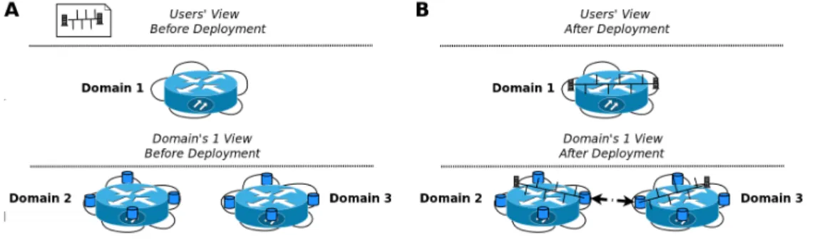
In a first step, user may care about the quality of service parameters for connecting two VMs or storage resources in different network locations (possibly located across several network operators). Most advanced application providers may also deal with specific policies and how packets are handled. The ability to customize path selection within a single domain is another of the advantages of the single router abstraction. In the delegation approach outlined in the previous section, this delegation implies that a given domain may need to pass some of these policies down to the underlying domains and make sure that the aggregation of paths in several domains still comply with the user’s specified requirements. In Figure 3.5 one can observe how this delegation approach works in the single domain abstraction. Domain 1 is deploying several VMs in several other domains (since it does not have any actual resources of its own). Domain 1 users see the whole network as a single router to which their VMs can be linked. Domain 1 is hiding the underlying complexity and the information provided by the underlying domains with regards to their neighbours. Domain 1 makes the decision to split the request and deploy the VMs in two different domains. Based on the information exported by domain 2 and 3 about their connectivity (e.g. Domain 1: can connect to domain 2 via Multiprotocol Label Switching (MPLS) or via L3 VPNs at endpoints A, and B with different UUIDs), Domain 1 informs the underlying domains about their need to talk and negotiate in order to get the chosen link (e.g. MPLS connection) ready. Please note that a single switch abstraction is also applicable here, depending on the connectivity level requested by the end user (L2, L3, flowcontrols). This is why we will refer to the single node abstraction as a general case of the single router abstraction introduced by this example.
In this scenario, the concept of the endpoint becomes prominent (represented with the darker blue cylinders in Figure 3.5). And endpoint is nothing else than the concept of a router interface taken to a higher abstraction level. It can be just another resource of the cloud (a VM or physical router) that needs to be properly configured (like, for instance, Ciscos’ routers via its IOS com-mands per interface and protocol). The data model to be used needs to deal with the abstraction of the endpoint (single router interface) and its configuration protocols. Obviously, the specific configuration may be hidden from the user domain and some type of negotiation may take place
between two neighbouring endpoints so as to agree in some parameters (for instance, the transmis-sion rate). Roughly, the idea is to introduce a new network-wide software layer that exposes one or more logical forwarding elements
Figure 3.5: Single Router (Node) View of the Network of a Domain.
This darker blue cylinders (endpoint or ports of our single router) are the key elements that need to be defined and integrated at a later design stage in order to guarantee that users deploying services in the federated cloud get the network features that are truly relevant for their applications’ proper performance. At an architectural level, the endpoints will include two major interfaces:
• External Domain (client) Interface: it exposes endpoint configuration or negotiation
capabil-ities as a service for external users. For example, a client domain may decide to connect two neighbouring domains by using any available endpoint in that inter-domain junction.
• Internal Domain (provider) Interface: the domain receives the external (client) domain
re-quests and maps it to a series of internal operations and actuations on a series of devices that bring the required elements up to work. For instance, an L3 VPN with some Quality of Service (QoS) guarantees is to be established with a remote endpoint indicated in the request. While the specifics of the internal domain interface are operator-dependent, the external interface should be built following a bottom up approach. In other words, getting data from the available technologies implemented at these junctions (and across operators) so as to build a common set of abstract operations and data types to be used ubiquitously, granting that a request can be placed no matter the actual technologies and policies implemented by final (the one that does no delegation at all and owns the infrastructure) domain.
3.3.2 Goal Translation and Data Model Refinement Synchronisation
The level of specification and the details about the data model vary according to the level of our architecture. The information and the data model vision of a user requesting a service are different from those explored by the infrastructure provider. A high level description is refined and formatted with information coming from management framework. For exemplifying the expression of user’s requests and the goal translation considering our data model, we selected a scenario were one is requesting a traditional IaaS, informing some elasticity configuration as well as the network requirements. At a very high level the goals expressed by the user could look something like the following:
• 10 VMs and connect them to my two enterprise sites, Madrid and London. VMs: 2 vCPU,
4GB RAM, 120GB HDD, Linux OS, Internet connection, located in Germany.
• I want to be able to scale up to 50 VMs (i.e. the minimum I want is 10, and I can go to a