Release Supplement
1/10Gb Uplink Ethernet Switch Module
Version 6.7
Copyright © 2011 BLADE Network Technologies, an IBM company, 2051 Mission College Blvd., Santa Clara, California, 95054, USA. All rights reserved. Reference number: BMD00276-A © Copyright IBM Corporation 2011.
US Government Users Restricted Rights – Use, duplication or disclosure restricted by GSA ADP Schedule Contract with IBM Corp.
This document is protected by copyright and distributed under licenses restricting its use, copying, distribution, and decompilation. No part of this document may be reproduced in any form by any means without prior written authorization of BLADE Network Technologies. Documentation is provided “as is” without warranty of any kind, either express or implied, including any kind of implied or express warranty of non-infringement or the implied warranties of merchantability or fitness for a particular purpose.
U.S. Government End Users: This document is provided with a “commercial item” as defined by FAR 2.101 (Oct. 1995) and contains “commercial technical data” and “commercial software
documentation” as those terms are used in FAR 12.211-12.212 (Oct. 1995). Government End Users are authorized to use this documentation only in accordance with those rights and restrictions set forth herein, consistent with FAR 12.211- 12.212 (Oct. 1995), DFARS 227.7202 (JUN 1995) and DFARS 252.227-7015 (Nov. 1995).
BLADE Network Technologies reserves the right to change any products described herein at any time, and without notice. BLADE Network Technologies assumes no responsibility or liability arising from the use of products described herein, except as expressly agreed to in writing by BLADE Network Technologies. The use and purchase of this product does not convey a license under any patent rights, trademark rights, or any other intellectual property rights of BLADE Network Technologies.
BLADE Network Technologies, the BLADE logo, BLADEHarmony, BNT, NMotion, RackSwitch, Rackonomics, RackSwitch Solution Partner, ServerMobility, SmartConnect and VMready are trademarks of BLADE Network Technologies. All other names or marks are property of their respective owners.
The 1/10Gb Uplink Ethernet Switch Module (GbESM) is one of up to four switch modules that can be installed in the IBM BladeCenter chassis.
This release supplement provide the latest information regarding BLADEOS 6.7 for the 1/10Gb Uplink ESM (referred to as GbESM throughout this document).
This supplement modifies and extends the following BLADEOS 6.5 documentation for use BLADEOS 6.7:
BLADEOS 6.5 Application Guide BLADEOS 6.5 Command Reference BLADEOS 6.5 ISCLI Reference BLADEOS 6.5 BBI Quick Guide
1/10Gb Uplink Ethernet Switch Module Installation Guide
The publications listed above are available from the IBM support website: http://www.ibm.com/systems/support
Hardware Support
BLADEOS 6.7 software is supported only on the 1/10Gb Uplink Ethernet Switch Module for IBM
BladeCenter. The 1/10Gb Uplink ESM (GbESM) shown in Figure 1 is a high performance Layer
2-3 embedded network switch that features tight integration with IBM BladeCenter management modules.
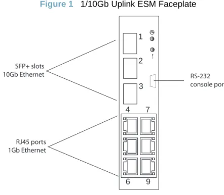
Figure 1 1/10Gb Uplink ESM Faceplate
The GbESM has the following port capacities:
Three external 10Gb SFP+ slots
Six external 1Gb Ethernet ports (RJ45)
One RS-232 serial console port
Two 100Mb internal management ports
Fourteen 1000Mb Ethernet internal ports
RS-232 console port 1
2
3 4 7
6 9 RJ45 ports
1Gb Ethernet SFP+ slots 10Gb Ethernet
Updating the Switch Software Image
The switch software image is the executable code running on the GbESM. A version of the image comes pre-installed on the device. As new versions of the image are released, you can upgrade the software running on your switch. To get the latest version of software supported for your GbESM, go to the following website:
http://www.ibm.com/systems/support
To determine the software version currently used on the switch, use the following switch command:
The typical upgrade process for the software image consists of the following steps:
Load a new software image and boot image onto an FTP or TFTP server on your network.
Transfer the new images to your switch.
Specify the new software image as the one which will be loaded into switch memory the next
time a switch reset occurs.
Reset the switch.
For instructions on the typical upgrade process using the CLI, ISCLI, or BBI, see “Loading New Software to Your Switch” on page 7.
>> # /boot/cur
!
Caution—Although the typical upgrade process is all that is necessary in most cases, upgrading from (or reverting to) some versions of BLADEOS requires special steps prior to or after the soft-ware installation process. Please be sure to follow all applicable instructions in the following sec-tions to ensure that your switch continues to operate as expected after installing new software.Special Software Update Issues
When updating to BLADEOS 6.7, the following special conditions may apply, depending on the version of software currently installed on your switch. These conditions are cumulative: If updating from version 2.0 (for example), follow the recommendations in order, beginning with those for 2.0, and then continue with all that apply, such as for “3.0 and prior,” “4.0 and prior,” and so on.
Updating from BLADEOS 5.x or Prior
After updating:
The STG port priority value is different compared to release 5.x and prior. In release 5.x and prior, the priority value could be set to any integer from 0 to 255. In release 6.3 and later, the range is still 0 to 255, but must be specified in increments of 4 (such as 0, 4, 8, 12, and so on). If the specified value is not evenly divisible by 4, the value will be automatically rounded down to the nearest valid increment whenever manually changing the priority value, when loading a configuration from prior to release 6.3, and during the software upgrade process. If using STG port priorities, after upgrading to release 6.3 or later, it is recommended that the administrator review the configured values and make any appropriate changes. (ID: 38556)
Updating from BLADEOS 6.1 or Prior
The BLADEOS 6.7 software image is not compatible with earlier BLADEOS 6.1 image storage buffers. When updating from BLADEOS 6.1 or prior, first install and boot BLADEOS 6.3 (instead of BLADEOS 6.7).
Booting with BLADEOS 6.3 will prepare switch for the expanded BLADEOS 6.7 image file. The switch can then be upgraded to BLADEOS 6.7 using the regular update procedures.
After updating:
Some time zones are different compared to release 6.1.2 and prior. After upgrading to release 6.3 or later, it is recommended that the administrator review the configured time zone and make any appropriate changes. (ID: 29778)
Updating from BLADEOS 6.5.1 or Prior
After updating:
The default value for port flow control for external uplink ports is different compared to release 6.5.1 or prior. After upgrading to release 6.5.2 or later, it is recommended that the administrator review the configured flow control settings and make any appropriate changes. (ID: 43781)
!
Caution—If currently using BLADEOS 6.1 or prior, do not upgrade directly to BLADEOS 6.7. To do so could cause the upgrade to fail. If the switch does not boot after an upgrade attempt, seeUpdating from BLADEOS 6.6 or Prior
After updating:
The default mode for Spanning Tree is different compared to prior releases. The default mode
is now PVRST. After upgrading, it is recommended that the administrator review the STP settings and make any appropriate changes.
Loading New Software to Your Switch
The GbESM can store up to two different switch software images (called image1 and image2) as well as special boot software (called boot). When you load new software, you must specify where it should be placed: either into image1, image2, or boot.
For example, if your active image is currently loaded into image1, you would probably load the new image software into image2. This lets you test the new software and reload the original active image (stored in image1), if needed.
To load a new software image to your switch, you will need the following:
The image and boot software loaded on an FTP or TFTP server on your network.
Note: Be sure to download both the new boot file and the new image file.
The hostname or IP address of the FTP or TFTP server
Note: The DNS parameters must be configured if specifying hostnames.
The name of the new software image or boot file
When the software requirements are met, use one of the following procedures to download the new software to your switch. You can use the BLADEOS CLI, the ISCLI, or the BBI to download and activate new software.
!
Caution—When you upgrade the switch software image, always load the new boot image and the new software image before you reset the switch. If you do not load a new boot image, your switch might not boot properly (To recover, see “Recovering from a Failed Upgrade” on page 22).Loading Software via the BLADEOS CLI
1. Enter the following Boot Options command:
2. Enter the name of the switch software to be replaced:
3. Enter the hostname or IP address of the FTP or TFTP server.
4. Enter the name of the new software file on the server.
The exact form of the name will vary by server. However, the file location is normally relative to the
FTP or TFTP directory (usually /tftpboot).
5. Enter your username for the server, if applicable.
If entering an FTP server username, you will also be prompted for the password. The system then prompts you to confirm your request. Once confirmed, the software will load into the switch. 6. If software is loaded into a different image than the one most recently booted, the system will
prompt you whether you wish to run the new image at next boot. Otherwise, you can enter the
following command at the BootOptions# prompt:
The system then informs you of which software image (image1 or image2) is currently set to be loaded at the next reset, and prompts you to enter a new choice:
Specify the image that contains the newly loaded software.
7. Reboot the switch to run the new software:
The system prompts you to confirm your request. Once confirmed, the switch will reboot to use the new software.
>> # /boot/gtimg
Enter name of switch software image to be replaced ["image1"/"image2"/"boot"]: <image>
Enter hostname or IP address of FTP/TFTP server: <hostname or IP address>
Enter name of file on FTP/TFTP server: <filename>
Enter username for FTP server or hit return for TFTP server: {<username>|<Enter>}
Boot Options# image
Currently set to use switch software "image1" on next reset. Specify new image to use on next reset ["image1"/"image2"]:
Loading Software via the ISCLI
1. In Privileged EXEC mode, enter the following command:
2. Enter the hostname or IP address of the FTP or TFTP server.
3. Enter the name of the new software file on the server.
The exact form of the name will vary by server. However, the file location is normally relative to the
FTP or TFTP directory (for example, tftpboot).
4. If required by the FTP or TFTP server, enter the appropriate username and password.
5. The switch will prompt you to confirm your request.
Once confirmed, the software will begin loading into the switch.
6. When loading is complete, use the following commands to enter Global Configuration mode to
select which software image (image1 or image2) you want to run in switch memory for the next reboot:
The system will then verify which image is set to be loaded at the next reset:
7. Reboot the switch to run the new software:
The system prompts you to confirm your request. Once confirmed, the switch will reboot to use the new software.
Router# copy {tftp|ftp} {image1|image2|boot-image}
Address or name of remote host: <name or IP address>
Source file name: <filename>
Router# configure terminal
Router(config)# boot image {image1|image2}
Next boot will use switch software image1 instead of image2.
Loading Software via BBI
You can use the Browser-Based Interface to load software onto the GbESM. The software image to load can reside in one of the following locations:
FTP server
TFTP server
Local computer
After you log onto the BBI, perform the following steps to load a software image: 1. Click the Configure context tab in the toolbar.
2. In the Navigation Window, select System > Config/Image Control. The Switch Image and Configuration Management page appears.
3. If you are loading software from your computer (HTTP client), skip this step and go to the next. Otherwise, if you are loading software from a FTP/TFTP server, enter the server’s information in the FTP/TFTP Settings section.
4. In the Image Settings section, select the image version you want to replace (Image for Transfer). If you are loading software from a FTP/TFTP server, enter the file name and click Get Image.
If you are loading software from your computer, click Browse.
In the File Upload Dialog, select the file and click OK. Then click Download via Browser. Once the image has loaded, the page refreshes to show the new software.
New and Updated Features
BLADEOS 6.7 for 1/10Gb Uplink Ethernet Switch Module (GbESM) has been updated to a Virtual Link Aggregation Groups (VLAGs) and other features.
The list of features below summarizes the updated features. For more detailed information about
configuring GbESM features and capabilities, refer to thecomplete BLADEOS 6.7 documentation
as listed on page 3.
Advanced Buffer Optimization
In BLADEOS 6.7, the 1/10Gb Uplink ESM allows advanced administrators to optimize port ingress and egress buffers for their particular network application.
Buffer configuration is available using the following menu:
To reset individual parameters to the recommended internal default values, specify 0 as the value. For example:
To reset all ingress buffer parameters, use the following command:
!
Caution—Do not upgrade directly to BLADEOS 6.7 if currently using BLADEOS 6.1 or prior. See “Updating from BLADEOS 6.1 or Prior” on page 6 for appropriate upgrade procedures.> # /cfg/qos/advbuf
!
Caution—Changing the port buffer settings can significantly alter switch performance. Improper settings can degrade or disrupt traffic. The default buffer values are broadly recommended for most applications. Before changing any buffer values, the administrator should be familiar with switch and network performance characteristics and able to perform a rigorous network evaluation to verify expected operation.> # /cfg/qos/advbuf/egress/totcell 0 0
Command Interface Enhancements
ISCLI Update
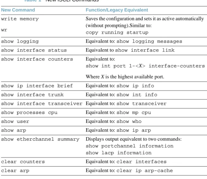
The ISCLI has been enhanced to be more consistent with common standards. The following command equivalents have been added:
Table 1 New ISCLI Commands
New Command Function/Legacy Equivalent
write memory wr
Saves the configuration and sets it as active automatically (without prompting).Similar to:
copy running startup
show logging Equivalent to: show logging messages show interface status Equivalent to show interface link show interface counters Equivalent to:
show int port 1-<X> interface-counters
Where X is the highest available port.
show ip interface brief Equivalent to: show ip info show interface trunk Equivalent to: show int info show interface transceiver Equivalent to: show transceiver show processes cpu Equivalent to: show mp cpu show user Equivalent to: show who show arp Equivalent to: show ip arp
show etherchannel summary Displays output equivalent to two commands:
show portchannel information show lacp information
clear counters Equivalent to: clear interfaces clear arp Equivalent to: clear ip arp-cache
Output Filtering
Some commands designed to display configuration settings or other switch information can potentially generate lengthy output. For circumstances where only a specific portion of the output is of interest to the administrator, the switch now provides command filters for limiting switch output.
Applicable Commands
Output filters can be applied to the following types of commands:
In the menu-based CLI:
All commands under the Information menu (/info) and its sub-menus
All cur commands
In the Industry-Standard CLI (ISCLI), all show commands
Filter Types
The following types of filters are available:
Include Lines—Display only the lines that include a specified regular expression. Format:
<command> | include <RegEx>
For example, to display the line that includes the string “MAC” (containing the switch’s MAC address and primary IP interface address):
Exclude Lines—Display all lines except those that include a specified regular expression. Format:
<command> | exclude <RegEx>
Set Beginning—Display the output beginning from the line that includes a specified regular
expression. Format:
<command> | begin <RegEx>
Set Section—For output that includes different sections, display only the section of the output that includes a specified regular expression. Format:
<command> | section <RegEx>
Global Flooding Options
Options for configuring flooding are no longer available under the IGMP menus. Instead, flooding
commands have been moved to the VLAN Flooding menu (/cfg/l3/flooding/vlan) and
are available regardless of the IGMP state.
Any existing flooding configuration is preserved and automatically converted to the new command location when upgrading to BLADEOS 6.7 or higher. When loading configuration files from versions prior to BLADEOS 6.7, any flooding configuration in the files are automatically converted.
In addition, a new option in the VLAN Flooding menu for optimized flooding (optflood) has
been added. When enabled, optimized flooding avoids packet loss during the learning period. This option is disabled by default.
IPv6 Enhancements for NIST USGv6
To support the National Institute of Standards and Technology (NIST) recommendations for IPv6 implementations, BLADEOS 6.7 IPv6 feature compliance has been extended to include the following IETF RFCs, with an emphasis on IP Security (IPsec) and Internet Key Exchange version 2, Multicast Listener Discovery (MLD) versions 1 and 2, and authentication/confidentiality for OSPFv3:
RFC 2740 for OSPF
RFCs 3306 and 3307 for dynamic IPv6 multicast addresses
RFC 3810 for MLDv2
RFC 4301 for IPv6 security
RFC 4302 for the IPv6 Authentication Header
RFCs 2404, 2410, 2451, 3602, and 4303 for IPv6 Encapsulating Security Payload (ESP),
including NULL encryption, CBC-mode 3DES and AES ciphers, and HMAC-SHA-1-96.
RFCs 4306, 4307, 4718, and 4835 for IKEv2 and cryptography
RFC 4552 for OSPFv3 IPv6 authentication
IPsec/IKE for IPv6
Internet Protocol Security (IPsec) is a protocol suite for securing Internet Protocol (IP) communications by authenticating and encrypting each IP packet of a communication session. IPsec also includes protocols for establishing mutual authentication between agents at the beginning of the session and for the negotiation of cryptographic keys to be used during the session.
The BLADEOS implementation of IPsec supports the following protocols:
Authentication Header (AH)
AHs provide connectionless integrity and data origin authentication for IP packets, and provide protection against replay attacks. In IPv6, the AH protects the AH itself, the Destination Options extension header after the AH, and the IP payload. It also protects the fixed IPv6 header and all extension headers before the AH, except for the mutable fields DSCP, ECN, Flow Label, and Hop Limit. AH is defined in RFC 4302.
Encapsulating Security Payload (ESP)
ESPs provide confidentiality, data origin authentication, connectionless integrity, an anti-replay service (a form of partial sequence integrity), and some traffic flow confidentiality. ESPs may be applied alone or in combination with an AH. ESP is defined in RFC 4303.
Internet Key Exchange (IKE)
IKE is used for mutual authentication between two network elements. An IKE establishes a security association (SA) that includes shared secret information to efficiently establish SAs for ESPs and AHs, and a set of cryptographic algorithms to be used by the SAs to protect the associated traffic. IKE is defined in RFCs 4109 (IKEv1) and 4306 (IKEv2).
Using IKE as the foundation, IPsec supports ESP for encryption and/or authentication, and/or AH for authentication of the remote partner.
To configure IPsec, you must define a key policy. The following is needed to configure a manual key policy:
The IP address of the peer—This may be in either IPv4 or IPv6 format.
The traffic selector—This describes the packets to which the policy applies.
The transform set—This defines which encryption and authentication algorithms are used.
Inbound/Outbound session keys for the security protocols.
You can then assign the policy to an interface. The peer represents the other end of the security association. The security protocol for the session key is either ESP or AH. Outgoing packets are
Loopback Interfaces
A loopback interface provides an IP address, but is not otherwise associated with a physical port or network entity. Essentially, it is a virtual interface that is perceived as being “always available” for higher-layer protocols to use and advertise to the network, regardless of other connectivity. Loopback interfaces improve switch access, increase reliability, security, and provide greater flexibility in Layer 3 network designs. They can be used for many different purposes, but are most commonly for management IP addresses, router IDs for various protocols, and persistent peer IDs for neighbor relationships.
In BLADEOS 6.7, loopback interfaces have been expanded for use with routing protocols such as OSPF and BGP. Loopback interfaces can also be specified as the source IP address for syslog, SNMP, RADIUS, TACACS+, NTP, and router IDs.
Loopback interfaces must be configured before they can be used in other features. Up to 5 loopback interfaces are currently supported. They can be configured using the following commands:
Loopback Interfaces in OSPF
Because loopback interfaces are always available on the switch, loopback interfaces may present an advantage when used as the router ID.
If dynamic router ID selection is used, loopback interfaces can be used to force router ID selection. If a loopback interface is configured, its IP address is automatically selected as the router ID, even if other IP interfaces have lower IP addresses. If more than one loopback interface is configured, the lowest loopback interface IP address is selected.
Loopback interfaces can be advertised into the OSPF domain by specifying an OSPF host route with the loopback interface IP address.
Note – Loopback interfaces are not advertised via the OSPF route redistribution of fixed routes. To enable OSPF on an existing loopback interface:
GbESM(config)# interface loopback <1-5>
GbESM(config-ip-loopback)# [no] ip address <IPv4 address> <mask> enable GbESM(config-ip-loopback)# exit
GbESM(config)# interface loopback <1-5>
GbESM(config-ip-loopback)# ip ospf area <area ID> enable GbESM(config-ip-loopback)# exit
Loopback Interfaces in BGP
In many networks, multiple connections may exist between network devices. In such environments, it may be useful to employ a loopback interface for a common BGP router address, rather than peering the switch to each individual interface.
When a loopback interface is created for BGP, the switch automatically uses the loopback interface as the BGP peer ID, instead of the switch’s local IP interface address.
Note – To ensure that the loopback interface is reachable from peer devices, it should be advertised using an interior routing protocol (such as OSPF), or a static route should be configured on the peer. To configure an existing loopback interface for BGP neighbor use:
Using Loopback Interfaces for Source IP Addresses
The switch can use loopback interfaces to set the source IP addresses for a variety of protocols. This assists in server security, as the server for each protocol can be configured to accept protocol packets only from the expected loopback address block. It may also make is easier to locate or process protocol information, since packets have the source IP address of the loopback interface, rather than numerous egress interfaces.
Configured loopback interfaces can be applied to the following protocols:
Syslogs
SNMP traps
RADIUS
GbESM(config)# router bgp
GbESM(config-router-bgp)# neighbor <#> update-source loopback <1-5>
GbESM(config-router-bgp)# exit
GbESM(config)# logging source-interface loopback <1-5>
GbESM(config)# snmp-server trap-source loopback <1-5>
Loopback Interface Limitation
ARP is not supported. Loopback interfaces will ignore ARP requests.
Loopback interfaces cannot be assigned to a VLAN.
MLD for IPv6
Multicast Listener Discovery (MLD) is an IPv6 protocol that a host uses to request multicast data for a particular group. Using the information obtained through MLD, the software maintains a list of multicast group or channel memberships on a per-interface basis. MLD is defined in RFC 2710 (MLDv1) and RFC 3810 (MLDv2).
Customers that use IPv6 messages to subscribe to group memberships use MLD so each multicast router can learn, for each of its directly attached links, which multicast addresses and which sources have interested listeners on its links. The information gathered by MLD is provided to whichever multicast routing protocol is used by the router to ensure that multicast packets are delivered to all links where there are listeners interested in such packets.
STP with Automatic STG Assignment
The Spanning Tree feature has been enhanced to simplify switch configuration. To begin, PVRST is now the default Spanning-Tree mode. The previous default was STP/PVST+ mode (see the BLADEOS 6.5 Application Guide for details on Spanning Tree Protocols).
In addition, VLAN Automatic STG Assignment (VASA) is now available in PVRST mode. With VASA enabled, it is no longer necessary to manually assign Spanning-Tree Groups (STGs) for each VLAN. Instead, STG assignment is automated.
Each time a new VLAN is configured, the switch will automatically assign the new VLAN its own STG. Conversely, when a VLAN is deleted, if its STG is not associated with any other VLAN, the STG is returned to the available pool. If an empty STG is not available when creating a new VLAN, the default STG (STG 1) is automatically assigned.
VASA is enabled by default, but can be disabled or re-enabled using the following commands:
VASA applies only to PVRST mode and is ignored in RSTP and MSTP modes.
When VASA is enabled, manual STG assignment is still available. The administrator may assign a specific STG to a VLAN using regular commands:
>> # /cfg/l2/vlanstg e|d
Trunking
LACP Minimum Links
For dynamic trunks that require a guaranteed amount of bandwidth in order to be considered useful, it is now possible to specify the minimum number of links for the trunk. If the specified minimum number of ports are not available, the trunk link will not be established. If an active LACP trunk loses one or more component links, the trunk will be placed in the down state if the number of links falls below the specified minimum. By default, the minimum number of links is 1, meaning that LACP trunks will remain operational as long as at least one link is available.
The LACP minimum links setting can be configured as follows:
LAG Group Statistics
Statistics are now available for trunk group ports using the following command:
For static trunks, port statistics are collected for all enabled ports in the trunk group.
For dynamic, LACP trunks, port statistics are collected for all active ports in the trunk group.
Other Features and Enhancements
VMready Support for VMware ESX 4.1.
Digital optical monitoring (DOM) signal strength levels (TXuW and RXuW) are now shown in
the output of the showtransceiver command.
> # /cfg/l2/lacp/port <port number or range>/minlinks <minimum links>
Resolved Issues
Fixed a condition where, some of the IGMP configuration parameters were reset after stack
master failback when the switch is in stacking mode. (ID 48515)
Fixed a condition in OSPFv3 where ECMP routes were removed when a port was removed
from a trunk. (ID 50221)
The administrator is no allowed to change the configuration of the Spanning-Tree Group (STG)
128, which is reserved for switch management traffic. (ID 50435)
Fixed a condition where the switch was unexpectedly reset when trying to upgrade the boot
Supplemental Information
This section provides additional information about configuring and operating the GbESM and BLADEOS.
The Boot Management Menu
The Boot Management menu allows you to switch the software image, reset the switch to factory defaults, or to recover from a failed software download.
You can interrupt the boot process and enter the Boot Management menu from the serial console port. When the system displays Memory Test, press <Shift B>. The Boot Management menu appears.
The Boot Management menu allows you to perform the following actions:
To change the booting image, press 1 and follow the screen prompts.
To change the configuration block, press 2, and follow the screen prompts.
To perform an Xmodem download, press 3 and follow the screen prompts.
To exit the Boot Management menu, press 4. The booting process continues.
Resetting the System ...
Memory Test ... Boot Management Menu
1 - Change booting image 2 - Change configuration block 3 - Xmodem download
4 - Exit
Please choose your menu option: 1
Current boot image is 1. Enter image to boot: 1 or 2: 2 Booting from image 2
Recovering from a Failed Upgrade
Use the following procedure to recover from a failed software upgrade. 1. Connect a PC to the serial port of the switch.
2. Open a terminal emulator program that supports XModem Download (for example, HyperTerminal,
CRT, PuTTY) and select the following serial port characteristics:
Speed: 9600 bps
Data Bits: 8
Stop Bits: 1
Parity: None
Flow Control: None
3. Boot the switch and access the Boot Management menu by pressing <Shift B> while the Memory Test is in progress and the dots are being displayed.
4. Select 3 for Xmodem download. When you see the following message, change the Serial Port
characteristics to 115200 bps:
5. Press <Enter> to set the system into download accept mode. When the readiness meter displays (a series of “C” characters), start XModem on your terminal emulator.
6. Select the Boot Image to download. The XModem initiates the file transfer. When the download is complete, a message similar to the following is displayed:
7. When you see the following message, change the Serial Port characteristics to 9600 bps: yzModem - CRC mode, 62494(SOH)/0(STX)/0(CAN) packets, 6 retries Extracting images ... Do *NOT* power cycle the switch.
**** VMLINUX **** Un-Protected 10 sectors
Erasing Flash... done Writing to Flash...done Protected 10 sectors
**** RAMDISK **** Un-Protected 44 sectors
Erasing Flash... done Writing to Flash...done Protected 44 sectors
**** BOOT CODE **** Un-Protected 8 sectors
Erasing Flash... done Writing to Flash...done Protected 8 sectors
10. Press <Enter> to continue the download.
11. Select the OS Image to download. The XModem initiates the file transfer. When the download is complete, a message similar to the following is displayed:
12. Select the image number to load the new image (1 or 2). It is recommended that you select 1. A message similar to the following is displayed:
13. When you see the following message, change the Serial Port characteristics to 9600 bps:
14. Press the Escape key (<Esc>) to re-display the Boot Management menu. 15. Select 4 to exit and boot the new image.
yzModem - CRC mode, 27186(SOH)/0(STX)/0(CAN) packets, 6 retries Extracting images ... Do *NOT* power cycle the switch.
**** Switch OS ****
Please choose the Switch OS Image to upgrade [1|2|n] :
Switch OS Image 1 ... Un-Protected 27 sectors
Erasing Flash... done Writing to Flash...done Protected 27 sectors
Management Module
The “Fast POST=Disabled/Enabled” inside the IBM management module Web interface “I/O
Module Admin Power/Restart” does not apply to the GbESM.
Solution: To boot with Fast or Extended POST, go to the “I/O Module Admin/Power/Restart” window. Select the GbESM, and then choose “Restart Module and Run Standard Diagnostics” or “Restart Module and Run Extended Diagnostics.”
The following table correlates the Firmware Type listed in the IBM management module’s Web
interface “Firmware VPD” window to the GbESM software version:
Within the IBM management module Web interface, the Java applets of “Start Telnet Session”
and “Start Web Session” do not support changing of default known ports 23 and 80 respectively.
Solution: If the Telnet or HTTP port on the GbESM is changed to something other than the default port number, the user must use a separate Telnet client or Web browser that supports specifying a non-default port to start a session to the GbESM user interface.
Management Module/GbESM Connectivity
Currently, the IBM management module is designed to provide one-way control of the GbESM. As a result, the GbESM may lose connectivity to the management module via the management port under the following conditions:
If new IP attributes are pushed from the management module to the GbESM while the IP
Routing table is full, the new attributes will not be applied.
Solution: Enable “External Management over all ports,” connect to the switch using other interface and then clear the routing table. Then push the IP address from the management module. If this does not work, use Solution 2 below.
Table 2 Firmware Type list Firmware Type Description
Boot ROM GbESM Boot code version
Main Application 1 Currently running image
Solution 1: If you should experience any connectivity issues between the switch module and the management module, go to the “I/O Module Configuration” window on the management module’s Web interface. Under the “New Static IP Configuration” section, click Save to trigger the management module to push the stored IP attributes to the switch module.
Solution 2: If Solution 1 does not resolve your connectivity issue, then go to the “I/O Module Admin/Power/Restart” window on the management module’s Web interface. Restart the switch module in question.
Solution 3: If this still does not resolve the issue, enable Preserve new IP configuration on all resets setting on the management module and restart the switch module via the “I/O Module
Admin/Power/Restart” window on the management module’s Web interface.
Note – As a rule, always use the management module Web interface to change the GbESM management IP attributes (IP address, mask and gateway), and then click Save to push the IP attributes to the switch module. Use of the command-line interface to change the switch module management IP attributes may result in duplicated entries for the management IP Interface in the switch route table and/or loss of connectivity via the management module.
Internal Port Autonegotiation
By default, link autonegotiation is turned on for internal ports. This is in contrast to external ports, where autonegotiation is off by default. Internal ports use autonegotiation in order to support the Wake-Over-LAN (WOL) features of some servers. If an attached server does not support autonegotiation or WOL, turn autonegotiation off for the internal port.
FTP/TFTP Directory Path
When you use the CLI to perform a FTP/TFTP file transfer, you cannot use a forward slash (/) in the directory path, unless it is preceded by a back slash (\). This issue occurs only when a full command is issued on one line.
For example, the following is invalid:
The following is correct:
# /boot/gtimg 1 10.10.10.2 image_directory/filename
Secure Management Network
The following GbESM attributes are reserved to provide secure management access to and from the IBM management module:
MGT1 (port 15) and MGT2 (port 16)
VLAN 4095
IP interface 128
Gateway 4
STG 128
For more information about remotely managing the GbESM through the external ports, see “Accessing the Switch” in the BLADEOS 6.7 Application Guide.
Note – The external uplink ports (EXTx) cannot be members of management VLANs.
Secure Shell (SSH)
Because SSH key generation is CPU intensive, the GbESM attempts to avoid unnecessary key generation. The process generates three server keys:
1. One key is generated to replace the current server key, if used.
2. A second key is generated as a spare, in case the current server key is used and the specified interval expires.
3. A third key is generated for use at the next reboot.
Therefore, if you never login via SSH, you will only see two key generation events. You may see all three events directly following a reboot. If you want to witness the key generation after the specified interval has expired, then you must login via SSH at least once during each expiration interval.
Spanning Tree Configuration Tips
To ensure proper operation with switches that use Cisco Per VLAN Spanning Tree (PVST+), you must do one of the following:
Syslog Configuration Tip
The facility parameter traditionally is used to correlate services (such as IP, CLI, etc.) to messages. This is done to distinguish between the different services that are running in the network/device. However, for the GbESM, there is a single configured facility value (0-7) used on all messages. By configuring a unique facility value for each switch, a single SYSLOG server can distinguish between the various GbESMs in the network. Refer to “System Host Log Configuration” in the Command Reference.
Trunk Group Configuration Tips
Please be aware of the following information when you configure trunk groups:
Always configure trunk groups first, on both ends, before you physically connect the links. Configure all ports in a trunk group to the same speed (you cannot aggregate 1Gb ports with
10GBASE-SFP+ ports).
vCenter Synchronization
When applying distributed VM group configuration changes, the switch will attempt to synchronize settings with the VMware vCenter for virtualization management. If the vCenter is unavailable, an error message will be displayed on the switch. Be sure to evaluate all error message and take the appropriate actions to ensure the expected changes are properly applied. If corrective actions are not taken, synchronization may remain incomplete when connection with the vCenter is restored. Solution: When the switch connection with the vCenter is restored, use the following operational command to force synchronization:
Known Issues
This section describes known issues for BLADEOS 6.7 on the 1/10Gb Uplink Ethernet Switch Module.
ACLs
When an Access Control List (ACL) is installed on two different ports, only one statistics counter will be available. The GbESM does not support two different statistics counter for one ACL installed on two different ports.
The ACL filters for TCP/UDP work properly only on packets that do not have IP options.
When you assign an ACL (or ACL Group) to one port in a trunk, BLADEOS does not
automatically assign the ACL to other ports in the trunk, and it does not prompt you to assign the ACL to other ports in the trunk. Manually assign each ACL or ACL Group to all ports in the trunk.
When configuring an ACL to set 802.1p priority for in-profile packets, and updating the DSCP
field using TOS bits for out-of-profile packets, the out-of-profile packets will have also the 802.1p priority set as defined in the in-profile setting.
Although the management port can be configured for port filtering option, actual port filtering will not occur, because the system filters out the management VLAN.
AMP
For proper AMP operation, all access switches should be configured with a higher priority value (lower precedence) than the aggregators. Otherwise, unexpected AMP keep-alive packets may be forwarded from one aggregator switch to the other, even when its AMP group is disabled. (ID: 37310)
BBI
Some versions of Microsoft Internet Explorer version 6.x do not perform HTTP download
efficiently. If you have one of these versions, HTTP software download might take much longer than expected (up to several minutes).
Boot Configuration Block
In the CLI, the boot configuration command (/boot/conf<block>) examines only the initial character of the block option. Invalid block strings (those other than active, backup, or
factory) that use a valid first character (a, b, or f) will be interpreted as the matching valid string. (ID: 42422)
Daylight Saving Time
For the Asia/Israel time zone, BLADEOS sets the end of Daylight Saving Time (DST) as the last week in September. However, because the observed end of DST varies according to the date of the Yom Kippur holiday in the Hebrew calendar since 2005, occurring on various Saturdays in September or October, the default DST rule may not work as desired.
For the Asia/Israel time zone, or any other time zone in which the start or end date of DST varies from year to year, the administrator should create a custom DST rule for those years in which DST is desired, but ends in a different week than the set by default.
Hotlinks
Prior to enabling hotlinks, Spanning-Tree should be globally disabled using the following command (ID: 47917):
IGMP
In IGMP relay, when having joins from multiple VLANs, and the multicast data transmitter is
on a VLAN that did not receive any joins, multicast data is routed only if the flood option is
disabled using the /cfg/l3/igmp/adv/flood d command.
In IGMP relay, if an IGMP v2 joins an IGMP group on the same port where an IGMP v1 join
has already been issued, the software will default to the IGMP v1 timeout value.
If a port has a static multicast router (Mrouter) configured, and you move the port to a different
VLAN, the static Mrouter appears in the /info/l3/igmp/mrouter/dump output for the
original VLAN. When you move the port to a new VLAN, remove the static Mrouter from the port, and add it again.
IP Gateways
Although the switch allows IPv4 gateways numbered 1 through 132 to be configured, the 1/10Gb Uplink ESM supports only IPv4 gateways numbered 1 to 4. IPv4 gateways 5 through 132 are not supported and should not be configured. (ID: 42433)
LACP
If a static trunk on a GbESM is connected to another GbESM with LACP configured (but no
active LACP trunk), the /info/l2/trunk command might erroneously report the static
trunk as forwarding.
Since LACP trunks use LACPDU packet to maintain trunking with the partner, there is a
possibility for those packets to be dropped from an extremely busy trunk. If this happens, some links in the LACP trunk might be removed, then aggregated back to the trunk if an LACPDU is received. To avoid this unstable LACP trunk link, you can add more links to the trunk to increase the bandwidth, or use regular static trunk if there are no more links available.
OSPF
Some changes to OSPF configuration (such as creating a new area or changing an area’s type)
may result in OSPF state reconvergence. (ID: 46445, 48483)
OSPFv3 over IPsec
This combination can only be configured only on a per-interface basis. Configuration
based on virtual links is not currently supported.
The current implementation for OSPFv3 allows the use of only one protocol (AH or ESP)
at any given time. AH and ESP cannot be applied together.
Password Expiration
If you configure a Strong Password with automatic expiration, the password might not expire if the system date and time is not configured first. Use of a Network Time Protocol (NTP) server resolves this issue.
Solution: When you configure a strong password with automatic expiration, first configure the system time and date for the switch.
Ports and Transceivers
When the link speed for an external connection is forced (i.e. no Auto-Negotiation) to 100 Mbps and then changed to 10 Mbps, if the external device is changed first, the external device may erroneously report the link as DOWN even after the GbESM is changed to 10 Mbps. Solution: At the external device, disconnect and reconnect the cable.
Interoperability with Older Hubs
The command-line interface might display link up and link down messages continuously for an external port that is connected to certain older hub models configured for 100 Mbps
half-duplex. The display might show link up erroneously. This behavior has been observed when connecting the GbESM with the following devices:
NETGEAR FE104 100 hub
SBS 1000Base-T NIC
3Com Linkbuilder FMS100 Hub 3C250 TX/I
3Com SuperStack II 100TX 3C250C-TX-24/12
Nortel Baystack 204 Hub
If the GbESM is connected to an application switch which requires a link speed of 100 Mbps half-duplex, then enable auto negotiation on the GbESM port with port speed=any, mode=any, fctl=both, and auto=on.
QoS Metering
Traffic may exceed the configured maximum burst size of the ACL meter
(/cfg/port <x>/aclqos/meter/mbsize) by one packet, with that packet remaining In-Profile. Once the ACL meter has been exceeded, additional burst packets fall Out-of-Profile.
RADIUS with SSHv2
With RADIUS turned on, users might see a duplicate login prompt for SSHv2 clients if the RADIUS server is too slow to respond or if the RADIUS server is not available. In this case, users must re-type the username and password to login.
SNMP
Due to backward-compatibility issues, two Routing Information Protocol (RIP) MIBs are
available in BLADEOS: ripCfg and rip2Cfg. Use the rip2Cfg MIB to configure RIPv1
and RIPv2 through SNMP.
BLADEOS does not support the standard RIPv2 MIB as described in RFC 1724. Use the
rip2Cfg MIB to configure RIPv1 and RIPv2 through SNMP.
Statistics
The counter for empty egress port map discards may increase on ports used for stacking. This is the because all multicast or broadcast traffic gets flooded to all stacking ports. Discard of these packets is normal and expected on the stacking ports.
Trunking
Multicast, broadcast and DLF (Destination Lookup Failure, which are unknown destination MAC packets) traffic is sent to the lowest numbered port in the trunk. If this port is down, then the traffic is sent to the next lowest-numbered port. If the port that was down comes up again, the traffic is not re-hashed back to the recovered port.
Tx Ring Loop
When you create a trunk or link loop between the GbESM and another switch, packets might loop infinitely at line rate within the related links. When this problem occurs, the GbESM continuously displays the following messages at the console:
WARNING: packet_sent u: 0, dv_active: tx ring full packet_sent dcnt=114, public1=110, vcnt=1025
Remove the loop to resolve this misconfiguration.
VMready
The GbESM does not support IPv6 on VMs. If a VM attached to the switch is using IPv6
addressing, the output of VM-related information commands (such as