International Journal of Science Engineering and Advance Technology,
IJSEAT, Vol. 4, Issue 7
ISSN 2321-6905
July -2016
Model and Design Control of PID and Fuzzy Controller Based
SAPF for Wind And Sun Based System
Bunga Arun Kumar, B.Trinadh
M-tech Student Scholar, Assistant Professor
Department of Electrical &Electronics Engineering,
Prasiddha College Of Engineering &Technology (PCET)
East Godavari (Dist.); A.P, India
Abstract:
In the midst of the past presences a while, fuzy controller relies on upon fuzy rationale included oversees in a beyond any doubt level of thoughts can't be imparted as the " honest to goodness" or "false" however a bit "to some extent certified" are most dynamic and beneficial reaches for examination organized applications especially in the area of mechanical system of information yield relations. The compensator is proposed for use with each individual disseminated range (DS) system in the littler scale grid, and involves two four - leg inverters (a plan and a shunt), in a perfect world controlled to finish a change of both the way of power within the scaled down scale system and the way of streams existing between the little scale cross section and use structure. The purpose behind a four-leg voltage-source inverter (4LVSI) permit the compensation of current consonant fixings, fusing unequal current made in single-stage nonlinear weights. A definite direct numerical model of shunt element channel, including the effect of power structure impedance, is give and used to diagram the perceptive control estimation. The vital pay of the proposed shunt dynamic power channel and took after control arrangement for persistent state and transient event conditions is showcases for the way of power through test results by MATLAB/SIMULINK.
Key words: Fuzzy controller, shunt active power filter, control of harmonics, predictive current control; four leg converters, and power improvement.
I. Introduction
In the blink of an eye a day's Renewable vitality sources (RESs) have experienced a quick advancement in Power time in light of mechanical
costs and extended their capability meanwhile to accomplish power demand as indicated by the need of power utilization over the geological extents. In any case, renewable vitality period incorporates power quality as a result of its non-linearity, so this non-linearity behavior of power time particularly changes the voltage control and makes an issue of voltage bowing in power systems. The need to arrange the renewable vitality like wind vitality/PV into power structure is to make it possible to minimize the environmental impact on standard plant [1]. The coordination of wind vitality into existing power structure presents specific troubles and that requires considered voltage direction, unfaltering quality, and force quality issues. The power quality is a key customer focused measure and is essentially impacted by the operation of a movement and transmission framework.
The issue of power quality is of uncommon noteworthiness to the wind turbine there has been an expansive improvement and expedient progression in the misuse of wind vitality starting late.
International Journal of Science Engineering and Advance Technology,
IJSEAT, Vol. 4, Issue 7
ISSN 2321-6905
July -2016
of the fact that it can quickly take after the present reference signal while keeping up a predictable dc-voltage. Along these lines, utilizations of insightful control in power converters have been used generally as a piece of artificiality motor drives. One purpose of inclination of the proposed estimation is that it fits well in element power channel applications, since the power converter yield parameters are most likely caught on. These yield parameters are gotten from the converter yield swell channel and the power structure corresponding impedance. The converter yield swell channel Is a bit of the dynamic power channel setup and the power structure impedance is procured from without a doubt comprehended standard procedures. Because of dark structure impedance parameters, an estimation technique can be used to gather an exact R–L rise to impedance model of the system.
Routinely, PI, PD and PID controller are most standard controllers and by and large used as a piece of most power electronic devices however starting late there are various authorities reported adequately grasped Fuzzy Logic Controller (FLC) to end up one of savvy controllers to their machines [3]. Concerning their powerful logic execution, this kind of system realized in this paper is using fuzy method of reasoning controller with contribution by presentation of voltage independently. The presentation of advancement in voltage in the circuit will be urged to fuzy controller to give reasonable measure on steady state signal. The fuzy reason controller serves as savvy controller for this propose. This paper demonstrates the numerical model of the 4L-VSI and the gauges of operation of the proposed judicious control arrangement, including the setup framework. The complete depiction of the picked current reference generator realized in the dynamic power channel is in like manner showed. Finally, the proposed dynamic power channel and the sufficiency of the related control arrangement pay, power quality change is reenacted using MATLAB/SIMULINK.
II. HYBRID POWER SYSTEM WITH FOUR -LEG CONVERTER MODEL
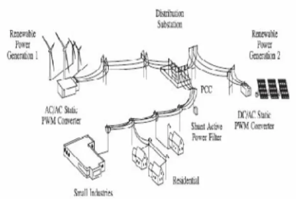
Fig 1 demonstrates the run of the mill power dissemination framework having different sorts loads and diverse era units, for example, wind and sun oriented (or) daylight, used to create power for private (or) household reason and little commercial
ventures.
Fig.1 hybrid power generation system with a Shunt active power filter.
Bothwind and sun oriented sorts of force era use air conditioning/air conditioning and dc/air conditioning static PWM converters for voltage transformation and battery banks for more vitality stockpiling. The PWM converters perform to cover the most extreme force tracks to remove the expansive measure of vitality from wind and sun powered. The utilization of electrical vitality might be adjusted or uneven, single or three stage and direct or nonlinear [8].
Fig.2.Three-phase equivalent circuit shunt active power filter.
International Journal of Science Engineering and Advance Technology,
IJSEAT, Vol. 4, Issue 7
ISSN 2321-6905
July -2016
Fig. 3.Two-level four-leg PWM-VSI topology.
By the expansion of fourth leg to the three-stage routine converter , builds changing states from enhancing control adaptability and yield quality .and is well prudent for current lopsided remuneration. The voltage at any leg "x" in the 4-leg converter measures from the nonpartisan point (n), can be composed as regarding exchanging states in this way
The mathematical model of the the filter derived from equivalent circuit shown in fig .2 is
Where Req and Leq are the 4L-VSI yield parameters communicated as The venin's impedances at the converter yield terminals Zeq . Along these lines, The venin's proportional impedance is dictated by an arrangement association of the swell channel impedance Zf and a parallel course of action between the framework identical impedance Zs and the heap impedance ZL.
For this model, it is assumed that ZL _ Zs, that theresistive part of the system’s equivalent impedance is
neglected, and that the series reactance is in the range of3–7% p.u., which is an acceptable approximation of thereal system. Finally,
Req = Rfand Leq = Ls+ Lf.
III. CURRENTCONTROL SCHEME
The sectional outline of current control plan is appeared in Fig .4 .The present control proposition is essentially required to current references, that are utilized to repays the undesirable burden parts. In this area the source voltage, load current and the dc-voltage converter are measured, while the characteristic streams are created precisely from the present reference generator.
Fig.4.Current control block diagram.
A converter is used to predict the output converter current, Both controller and framework converter must be spoken to as prescient model for knowing exchanging states and control variables. A dq-based current reference generator plan is utilized toget the dynamic force channel current reference signals.This outline gives a quick and precise sign trackingcapability. The dq current reference signal influencing the pay execution, to stayed away from voltage flections and in addition all out consonant contortions of the voltage.The removal power component (sin φ(L) ) and themaximum absolute symphonious mutilation of the heap (THD(L) )characterizes the connections between the evident powerrequired by the dynamic force channel, regarding the load,as appeared
International Journal of Science Engineering and Advance Technology,
IJSEAT, Vol. 4, Issue 7
ISSN 2321-6905
July -2016
[3], therelationship between the genuine streams iLx(t) (x = u, v,w) and the related dq components (id and iq)
Fig.5.dq-based current reference generator block diagram.
The subsequent signs i*d and i*q are changed back to a three-stage framework by applying the reverse Park and Clark change, The cut off recurrence of the LPF utilized as a part of this paper is 20 Hz. A low-pass channel (LPF) removes the dc part of thephase streams id to create the symphonious referencecomponents id . The receptive reference segments of thephase-streams are acquired by stage moving thecorresponding air conditioning and dc parts of iqby 180°. Inorder to keep the dc-voltage consistent, the adequacy of theconverter reference current must be altered by including anactive force reference signal iewith the d-part.
The current that flows through the neutral of the load iscompensated by injecting the same instantaneous valueobtained from the phase-currents, phase-shifted by 180°, asshown.
One of the significant points of interest of the dq-based current reference generator plan is that it permits the implementation of a straight controller in the dc voltage control circle. In any case, one essential disservice of the dq-based current reference outline calculation utilized to generate the present reference is that a second order harmonic segment is created in id and iq under unbalanced working conditions. The plentifulness of this harmonic relies on upon the percent of uneven load current (communicated as the relationship between the negative sequence current iL,2 and the positive grouping currentiL,1 ). The second-arrange consonant can't be removedfrom id and iq, and along these lines produces a third symphonious inthe reference current when it is changed over back to abc
outline [17]. Since the heap current does not have a thirdharmonic, the one produced by the dynamic force filterflows to the force framework.
A. DC Link Voltage Control
The dc-voltage converter is controlled with a customary PID controller. This is an essential issue in the evaluation, since the cost capacity is composed utilizing just current references, keeping in mind the end goal to stay away from the utilization of weighting factors. Generally, these weighting variables are obtained experimentally, and they are not very much characterized when different working conditions are required. Additionally, the moderate element reaction of the voltage crosswise over the electrolytic capacitor does not influence the current transient response. Thus, the PID controller speaks to a simple and compelling option for the dc-voltage control. The dc-voltage stays consistent (with a base worth of sqrt of 6vs(rms) ) until the dynamic force consumed by the converter reductions to a level where it can't to compensate for its misfortunes. The dynamic force consumed by the converter is controlled by modifying the adequacy of the dynamic force reference flag ie, which is in phase with every stage voltage. In the piece chart demonstrated in Fig. 5, the dc-voltage vdc is measured and after that compared with a steady reference esteem v*dc. The mistake (e) isprocessed by a PID controller, with additions, Kpand Ti.Both increases are computed by dynamic response necessity. Fig. 6 demonstrates that the yield of the PID controller is nourished to the dc-voltage exchange capacity Gs Which is spoken to by a first-arrange framework.
International Journal of Science Engineering and Advance Technology,
IJSEAT, Vol. 4, Issue 7
ISSN 2321-6905
July -2016
[3], therelationship between the genuine streams iLx(t) (x = u, v,w) and the related dq components (id and iq)
Fig.5.dq-based current reference generator block diagram.
The subsequent signs i*d and i*q are changed back to a three-stage framework by applying the reverse Park and Clark change, The cut off recurrence of the LPF utilized as a part of this paper is 20 Hz. A low-pass channel (LPF) removes the dc part of thephase streams id to create the symphonious referencecomponents id . The receptive reference segments of thephase-streams are acquired by stage moving thecorresponding air conditioning and dc parts of iqby 180°. Inorder to keep the dc-voltage consistent, the adequacy of theconverter reference current must be altered by including anactive force reference signal iewith the d-part.
The current that flows through the neutral of the load iscompensated by injecting the same instantaneous valueobtained from the phase-currents, phase-shifted by 180°, asshown.
One of the significant points of interest of the dq-based current reference generator plan is that it permits the implementation of a straight controller in the dc voltage control circle. In any case, one essential disservice of the dq-based current reference outline calculation utilized to generate the present reference is that a second order harmonic segment is created in id and iq under unbalanced working conditions. The plentifulness of this harmonic relies on upon the percent of uneven load current (communicated as the relationship between the negative sequence current iL,2 and the positive grouping currentiL,1 ). The second-arrange consonant can't be removedfrom id and iq, and along these lines produces a third symphonious inthe reference current when it is changed over back to abc
outline [17]. Since the heap current does not have a thirdharmonic, the one produced by the dynamic force filterflows to the force framework.
A. DC Link Voltage Control
International Journal of Science Engineering and Advance Technology,
IJSEAT, Vol. 4, Issue 7
ISSN 2321-6905
July -2016
Fig. 6. DC-voltage control block diagram.
The equivalent closed-loop transfer function of the givensystem with a PID controller.Since the time response of the dc-voltage control loop doesnot need to be fast, a damping factor ζ= 1and a natural angular speedωn= 2π· 100 rad/s are used to obtain acritically damped response with minimal voltageoscillation. The corresponding integral time Ti = 1/a (13)and proportional gain Kpcan be calculated as
IV.
FUZZY LOGIC CONTROLLER
L. A. Zadeh exhibited the principal paper on fuzy set hypothesis in1965. From that point forward, another dialect was produced todescribe the fuzy properties of reality, which are verydifficult and at some point even difficult to be describedusing traditional techniques. Fuzy set hypothesis has beenwidely utilized as a part of the control territory with some application topower framework [5]. fuzy controller depends on fuzy rationale included manages in a specific level of ideas can't be communicated as the " genuine" or "false" however a bit "incompletely genuine" are most dynamic and productive ranges for exploration situated applications particularly in the domain of modern procedure of info yield relations. A straightforward fuzy rationale control is fabricated upby a gathering of principles taking into account the human learning ofsystem conduct. Matlab/Simulink reproduction model isbuilt to consider the dynamic conduct of converter. Furthermore, configuration of fuzy rationale controller can provide desirable both little flag and huge sign dynamic performance at same time, which is impractical with linear control
has been potential capacity to enhance the power of converters.
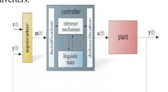
Fig.7 General Structure of the fuzzy logic controller.
The fundamental plan of a fuzy rationale controller is appeared in Fig 7.and comprises of four central componentssuch as: a deduction system, which changes over inputdata into appropriate phonetic qualities; a learning base,which comprises of an information base with the vital linguisticdefinitions and the control guideline set; a basic leadership
rationale which, mimicking a human choice procedure, infer the fuzy control activity from the information of the control rules and phonetic variable definitions; a de-fuzzification interface which yields non fuzy control activity from an inferred fuzy control activity [10].The fuzy control frameworks depend on master knowledge that changes over the human etymological ideas into an automatic control methodology with no complicated mathematical model.
Fig.8 Block diagram of the Fuzzy Logic Controller (FLC) for proposed converter
International Journal of Science Engineering and Advance Technology,
IJSEAT, Vol. 4, Issue 7
ISSN 2321-6905
July -2016
Fig. 6. DC-voltage control block diagram.
The equivalent closed-loop transfer function of the givensystem with a PID controller.Since the time response of the dc-voltage control loop doesnot need to be fast, a damping factor ζ= 1and a natural angular speedωn= 2π· 100 rad/s are used to obtain acritically damped response with minimal voltageoscillation. The corresponding integral time Ti = 1/a (13)and proportional gain Kpcan be calculated as
IV.
FUZZY LOGIC CONTROLLER
L. A. Zadeh exhibited the principal paper on fuzy set hypothesis in1965. From that point forward, another dialect was produced todescribe the fuzy properties of reality, which are verydifficult and at some point even difficult to be describedusing traditional techniques. Fuzy set hypothesis has beenwidely utilized as a part of the control territory with some application topower framework [5]. fuzy controller depends on fuzy rationale included manages in a specific level of ideas can't be communicated as the " genuine" or "false" however a bit "incompletely genuine" are most dynamic and productive ranges for exploration situated applications particularly in the domain of modern procedure of info yield relations. A straightforward fuzy rationale control is fabricated upby a gathering of principles taking into account the human learning ofsystem conduct. Matlab/Simulink reproduction model isbuilt to consider the dynamic conduct of converter. Furthermore, configuration of fuzy rationale controller can provide desirable both little flag and huge sign dynamic performance at same time, which is impractical with linear control
has been potential capacity to enhance the power of converters.
Fig.7 General Structure of the fuzzy logic controller.
The fundamental plan of a fuzy rationale controller is appeared in Fig 7.and comprises of four central componentssuch as: a deduction system, which changes over inputdata into appropriate phonetic qualities; a learning base,which comprises of an information base with the vital linguisticdefinitions and the control guideline set; a basic leadership
rationale which, mimicking a human choice procedure, infer the fuzy control activity from the information of the control rules and phonetic variable definitions; a de-fuzzification interface which yields non fuzy control activity from an inferred fuzy control activity [10].The fuzy control frameworks depend on master knowledge that changes over the human etymological ideas into an automatic control methodology with no complicated mathematical model.
International Journal of Science Engineering and Advance Technology,
IJSEAT, Vol. 4, Issue 7
ISSN 2321-6905
July -2016
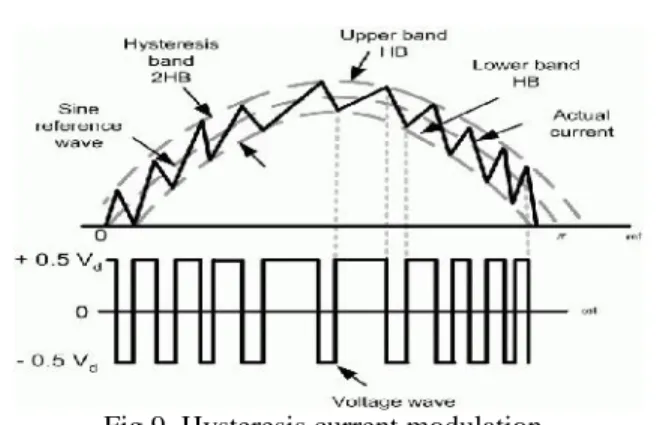
Fig.9. Hysteresis current modulation.
With the hysteresis control, limit groups are determined to eitherside of a sign speaking to the wanted yield waveform[6]. The inverter switches are worked as the generatedsignals inside points of confinement. The control circuit produces the sinereference signal flood of coveted size and frequency,and it is contrasted and the real flag. As the signalexceeds a recommended hysteresis band, the upper switch inthe half scaffold is killed and the lower switch isturned ON. As the sign crosses as far as possible, the lowerswitch is killed and the upper switch is turned ON.The genuine sign wave is in this way compelled to track the sinereference wave inside the hysteresis band limits.
V. MATLAB MODELEING AND SIMULATIONRESULTS
Fig.10 Simulink/Mat lab model for proposed RES 4-leg SAPF system with Fuzzy controller.
Results: Proposed SAPF with Knowledge based Fuzzy Controller
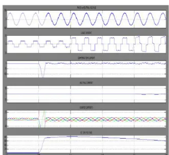
Fig.11 Simulation results for SAPF with Fuzzy Controller
(a) Source Voltage. (b) Load current. (c) Compensator Current. (d) Neutral Current, (e) Source Current (f) DC Link Voltage.
In Fig.11 showsSimulation results for SAPF knowledge based with Fuzzy Controller(a) Source Voltage. (b) Load current. (c) CompensatorCurrent, (d) Neutral Current, (e) Source Current (f) DCLink Voltage. Here compensator is turned on at 0.05seconds, before we get some harmonics coming from nonlinearload, then distorts our parameters and get sinusoidalwhen compensator is in on.
Fig.12 Power Factor forSAPF with Fuzzy Controller
Fig. 12 shows the power factor it is clear from the figureafter compensation power factor is unity.
Fig.13 shows the FFT Analysis of Phase-A Source Currentwith Fuzzy Controlled SAPF, here we get 0.95%.
2. Proposed RES Fed SAPF with PIDController
International Journal of Science Engineering and Advance Technology,
IJSEAT, Vol. 4, Issue 7
ISSN 2321-6905
July -2016
Fig.15 Simulation results for SAPF with Formal PIDController (a) Source Voltage. (b) Load current. (c) Compensator Current. (d) Neutral Current, (e) Source Current (f) DC Link Voltage.
Fig.15 Simulation results for SAPF with Formal PID Controller (a) Source Voltage. (b) Load current. (c) Compensator Current, (d) Neutral Current, (e) Source Current (f) DC Link Voltage. Here compensator is turned on at 0.05 seconds, before we get some harmonics coming from non-linear load, then distorts our parameters and get sinusoidal when compensator is in on.
Fig.16 Power Factor for SAPF with Conventional PID Controller
Fig. 16 shows the power factor it is clear from the figureafter compensation power factor is unity.
Fig. 17 FFT Analysis of Phase-A Source Current with PID
Fig.17 shows the FFT Analysis of Phase-A Source Current with PID Controlled APF, here we get 2.52%.
VI. CONCLUSION
This paper presents power quality change of the dissemination system with 4-L SAPF in light of Predictive control action. Upgraded component current sounds and a responsive power pay arrangement for power flow systems with period from renewable sources has been proposed to improve the present way of the spread structure. Purposes of enthusiasm of the proposed arrangement are related to its ease, illustrating, and utilization. This paper has shown a novel control of a present RES interfacing SAPF using standard PID controller and fuzy method of reasoning controller to upgrade the way of power at PCC for a 3-phase 4-wire structure. It has been exhibited that the SAPF structure can be enough utilized for power forming without affecting its normal operation of bona fide power trade. By using routine controller we get THD worth is 2.52%, however using the fuzy method of reasoning controller THD worth is 0.95%.controller and fuzy justification controller to improve the way of power at PCC for a 3-phase 4-wire structure. It has been exhibited that the SAPF system can be effectively utilized for power shaping without impacting its run of the mill operation of bona fide power trade. By using standard controller we get THD worth is 2.52%, however using the fuzy justification controller THD quality is 0.95%.
REFERENCES
[1] J. Rocabert, A. Luna, F. Blaabjerg, and P. Rodriguez, “Control ofpower converters in AC microgrids,” IEEE Trans. Power Electron., vol.27, no. 11, pp. 4734–4749, Nov. 2012.
[2] M. Aredes, J. Hafner, and K. Heumann, “Three -phase four-wire shuntactive filter control strategies,” IEEE Trans. Power Electron., vol. 12, no2, pp. 311– 318, Mar. 1997.
[3] S. Naidu and D. Fernandes, “Dynamic voltage restorer based on afourleg voltage source converter,” Gener.Transm.Distrib., IET, vol. 3,no. 5, pp. 437– 447, May 2009.
International Journal of Science Engineering and Advance Technology,
IJSEAT, Vol. 4, Issue 7
ISSN 2321-6905
July -2016
quality by using hybrid fuzzy controlledbased IPQC at various load conditions," Energy Efficient Technologiesfor Sustainability (ICEETS), 2013 International Conference on , vol., no.,pp.1243,1250, 10-12 April 2013..
[6] F. Wang, J. Duarte, and M. Hendrix, “Grid -interfacing convertersystems with enhanced voltage quality for microgridapplication;conceptand implementation,” IEEE Trans. Power Electron., vol. 26, no. 12, pp.3501–3513, Dec. 2011.
[7] X.Wei, “Study on digital pi control of current loop in active powerfilter,” in Proc. 2010 Int. Conf. Electr. Control Eng., Jun. 2010, pp.4287–4290. [8] R. de AraujoRibeiro, C. de Azevedo, and R. de Sousa, “A robustadaptive control strategy of active power filters for power-factorcorrection, harmonic compensation, and balancing of nonlinear loads,”IEEE Trans. Power Electron., vol. 27, no. 2, pp. 718–730, Feb. 2012.
[9] J. Rodriguez, J. Pontt, C. Silva, P. Correa, P. Lezana, P. Cortes, and U. Ammann, “Predictive current control of a voltage source inverter,”IEEE Trans. Ind. Electron., vol. 54, no. 1, pp. 495–503, Feb. 2007.
[10] Satyanarayana, G.; Ganesh, K.Lakshmi; Kumar, Ch. Narendra;Krishna, M.Vijaya, "A critical evaluation of power quality features usingHybrid Multi-Filter Conditioner topology," Green Computing,Communication and Conservation of Energy (ICGCE), 2013International Conference on , vol., no., pp.731,736, 12-14 Dec. 2013.
[11] R. Vargas, P. Cortes, U. Ammann, J. Rodriguez, and J. Pontt,
“Predictive control of a three-phase neutral-point-clamped inverter,”IEEE Trans. Ind. Electron., vol. 54, no. 5, pp. 2697–2705, Oct. 2007.
[12] P. Cortes, A. Wilson, S. Kouro, J. Rodriguez, and H. Abu-Rub,“Model predictive control ofmultilevel cascaded H-bridge inverters,”IEEE Trans. Ind. Electron., vol. 57, no. 8, pp. 2691–2699, Aug. 2010.
[13] P. Lezana, R. Aguilera, and D. Quevedo, “Model predictive controlof an asymmetric flying capacitor converter,” IEEE Trans. Ind. Electron.vol. 56, no. 6, pp. 1839–1846, Jun. 2009.
[14] P. Correa, J. Rodriguez, I. Lizama, and D. Andler, “A predictivecontrol scheme for current -source rectifiers,”IEEE Trans. Ind. Electron.,vol. 56, no. 5, pp. 1813–1815, May 2009.
[15] M. Rivera, J. Rodriguez, B. Wu, J. Espinoza, and C. Rojas, “Currentcontrol for an indirect matrix converter with filter resonance mitigation,”IEEE Trans. Ind. Electron., vol. 59, no. 1, pp. 71–79, Jan. 2012.
[16] P. Correa, M. Pacas, and J. Rodriguez, “Predictive torque control forinverter-fed induction machines,”IEEE Trans. Ind. Electron., vol. 54,no. 2, pp. 1073–1079, Apr. 2007.
[17] M. Odavic, V. Biagini, P. Zanchetta, M. Sumner, and M. Degano,“Onesample- period-ahead predictive current control for highperformanceactive shunt power filters,” Power Electronics, IET, vol. 4,no. 4, pp. 414–423, Apr. 2011.
[18] IEEE Recommended Practice for Electric Power Distribution forIndustrial Plants, IEEE Standard 141-1993, 1994
[19] R. de AraujoRibeiro, C. de Azevedo, and R. de Sousa, “A robustadaptive control strategy of active power filters for power-factorcorrection, harmonic compensation, and balancing of nonlinear loads,”IEEE Trans. Power Electron., vol. 27, no. 2, pp. 718–730, Feb. 2012.
[20] M. Sumner, B. Palethorpe, D. Thomas, P. Zanchetta, and M. DiPiazza, “A technique for power supply harmonic impedance estimationusing a controlled voltage disturbance,” IEEE Trans. Power Electron.,vol. 17, no. 2, pp. 207–215, Mar. 2002. [21] S. Ali, M. Kazmierkowski, “PWM voltage and current control offour-leg VSI,” presented at the ISIE, Pretoria, South Africa, vol. 1, pp.196–201, Jul. 1998