Accomplishment of Quasi Z Source Inverter towards Power
Maintenance for PV
S Asha Latha1, D Revathi2
M.Tech student1, Associate prof,viceprincipal,hod of EEE2 1Specialization power electronics in Electrical & Electronics Engineering, Kakinada Institute of Engineering and Technology,Andhra Pradesh,INDIA
Abstract
Semi Z Source Inverter (QZSI) an improvement to Z Source Inverter (ZSI). The benefits of QZSI can be recorded as lower segment appraisals, decreases exchanging ripples, reduced segment tally and rearranged control techniques. They can track the PhotoVoltaic (PV) panel most extreme power, control the inverter yield power and deal with the battery power. In a solitary stage inverter operation the voltage boosting, modifying and energy stockpiling are coordinated. From the PV panel, QZSI draws a consistent current. It controls the PV panel yield power to augment energy generation. EMI issues and source stretch are reduced, contrasted with the ZSI. QZSI is reasonable, when actualized with the Space Vector Pulse Width Modulation (SVPWM) control strategies for photovoltaic power age frameworks and could turn out to be profoundly effective.
Index terms: Maximum Power Point Tracking (MPPT), Z Source Inverter (ZSI), semi Z source inverter (QZSI), Shoot-Through (ST), Space Vector Pulse Width Modulation (SVPWM)
I. Introduction
The interest for electric energy is relied upon to increment quickly because of the worldwide populace development and industrialization. This expansion in the energy request requires electric utilities to expand their age. The broad utilization of non-renewable energy sources has brought about the worldwide issue of nursery discharges. Also, as the provisions of petroleum derivatives are drained later on, they will turn out to be progressively costly. To beat the issues related with age of electricity from petroleum derivatives, sustainable power sources can be taken an interest in the energy blend. In this way sun based energy is ending up more imperative since it creates less contamination and the cost of non-renewable energy source energy is rising, while the cost of sunlight based clusters is diminishing.
The regularly expanding energy utilization, petroleum products taking off expenses and modest
nature and intensifying worldwide condition have made a blasting enthusiasm for sustainable power source age frameworks, one of which is photovoltaic. Such a framework specifically changes over the sun powered radiation into electric power without hampering the earth. The overall introduced photovoltaic power limit demonstrates almost an exponential increment because of diminishing expenses and to enhancements in sunlight based energy innovation. In a customary VSI and CSI, the imperative that activating two info line changes prompts cut off source. The greatest possible yield voltage can't surpass the DC input and can deliver a voltage lower than the DC input voltage. Voltage source inverter can expect just eight unmistakable topologies. Six topologies delivers a non-zero yield voltage and are known as non-zero exchanging states and the staying two topologies produces zero yield voltage and are known as zero exchanging states. A. Quasi-Z-Source Inverter
The semi z-source inverter (QZSI) is a solitary stage power converter got from the Z-source inverter (ZSI) topology, utilizing an impedance organize. The impedance organize couples the source and the inverter to accomplish voltage lift and reversal in a solitary stage. Both ZSI and qZSI conquer the downsides of VSI and CSI by using a few ShootThrough (ST) zero states. A zero state is delivered when the upper three or lower three switches are let go at the same time to help the yield voltage. Supporting the six allowable dynamic exchanging conditions of a VSI, the zero states can be halfway or totally supplanted by the shoot through states relying on the voltage help prerequisite. The inverter draws a consistent current from the PV cluster and is equipped for dealing with a wide information voltage go. It additionally includes bring down part evaluations, decreases changing ripples to the PV panels, causes less EMI issues and reduced source push contrasted with the ZSI.
Accomplishment of Quasi Z Source Inverter towards Power
Maintenance for PV
S Asha Latha1, D Revathi2
M.Tech student1, Associate prof,viceprincipal,hod of EEE2 1Specialization power electronics in Electrical & Electronics Engineering, Kakinada Institute of Engineering and Technology,Andhra Pradesh,INDIA
Abstract
Semi Z Source Inverter (QZSI) an improvement to Z Source Inverter (ZSI). The benefits of QZSI can be recorded as lower segment appraisals, decreases exchanging ripples, reduced segment tally and rearranged control techniques. They can track the PhotoVoltaic (PV) panel most extreme power, control the inverter yield power and deal with the battery power. In a solitary stage inverter operation the voltage boosting, modifying and energy stockpiling are coordinated. From the PV panel, QZSI draws a consistent current. It controls the PV panel yield power to augment energy generation. EMI issues and source stretch are reduced, contrasted with the ZSI. QZSI is reasonable, when actualized with the Space Vector Pulse Width Modulation (SVPWM) control strategies for photovoltaic power age frameworks and could turn out to be profoundly effective.
Index terms: Maximum Power Point Tracking (MPPT), Z Source Inverter (ZSI), semi Z source inverter (QZSI), Shoot-Through (ST), Space Vector Pulse Width Modulation (SVPWM)
I. Introduction
The interest for electric energy is relied upon to increment quickly because of the worldwide populace development and industrialization. This expansion in the energy request requires electric utilities to expand their age. The broad utilization of non-renewable energy sources has brought about the worldwide issue of nursery discharges. Also, as the provisions of petroleum derivatives are drained later on, they will turn out to be progressively costly. To beat the issues related with age of electricity from petroleum derivatives, sustainable power sources can be taken an interest in the energy blend. In this way sun based energy is ending up more imperative since it creates less contamination and the cost of non-renewable energy source energy is rising, while the cost of sunlight based clusters is diminishing.
The regularly expanding energy utilization, petroleum products taking off expenses and modest
nature and intensifying worldwide condition have made a blasting enthusiasm for sustainable power source age frameworks, one of which is photovoltaic. Such a framework specifically changes over the sun powered radiation into electric power without hampering the earth. The overall introduced photovoltaic power limit demonstrates almost an exponential increment because of diminishing expenses and to enhancements in sunlight based energy innovation. In a customary VSI and CSI, the imperative that activating two info line changes prompts cut off source. The greatest possible yield voltage can't surpass the DC input and can deliver a voltage lower than the DC input voltage. Voltage source inverter can expect just eight unmistakable topologies. Six topologies delivers a non-zero yield voltage and are known as non-zero exchanging states and the staying two topologies produces zero yield voltage and are known as zero exchanging states. A. Quasi-Z-Source Inverter
B. QZSI Network
The impedance organize in QZSI varies from that of a ZSI. This system goes about as an interface between the source and the inverter. The impedance system of QZSI is a two port system. It comprises of inductors and capacitors. The LC impedance organize and the diode associated with the inverter connect change the circuit operation, permitting the shoot-through state and shield the circuit from harm when the shoot through happens. By utilizing the shoot-however express, the semi Zsource arrange helps the dc-connect voltage. The dc source can be a battery, diode rectifier, thyristor converter or PV exhibit. The yield voltage of the QZSI is directed and the yield power is dictated by relating load requests.
II. Traditional Methodology
The sunlight based illumination and the PV panel temperature change arbitrarily, the DC-connect top voltage will vary appropriately. The extra reinforcement is required like battery to supply the consistent power to the heap. Without prerequisites of any extra DC/DC converters or segments, the qZSI was first proposed for PV power age framework.
Fig.1 demonstrates the Existing QZSI for PV power age. This paper settle the previously mentioned issues, investigate every single conceivable plan of the energy-put away QZSI, think about their advantages and impediments and locate another topology more desirable over application in the PV power framework.
III. Proposed Topology
Fig.1 indicates only one of the qZSI topologies, if the battery is associated in parallel with the capacitor C2 there is intermittent mode will happen amid battery release.
Fig.2. Energy-put away QZSI with battery
As a partner, interface the battery in parallel to the capacitor C1 as appeared in Fig.2. They have basic focuses:
1) there are three power sources i.e., PV boards, battery and the network/stack, 2) insofar as controlling two power streams and 3) consequently coordinates the power distinction, as indicated by the power condition
Pin− Pout+ PB= 0 (1)
Where Pin, Pout and PB are the PV board power, yield power of the inverter and the battery power individually. The power Pin is constantly positive in light of the fact that the PV board is single directional power supply, Pout is sure when the inverter infuses power to the matrix and PB is certain when the battery conveys energy and negative while engrossing energy.
The Quasi z-source organize makes the shoot-through zero states conceivable and gives the methods by which boosting operation can be gotten. Basically, any of the shoot-through states can be substituted for typical zero states without influencing the PWM design seen by the heap. In this way, for a settled exchanging cycle, Instead, with the shoot-through states embedded, the powerful inverter dc interface voltage Vi can be ventured up as given in (2) Consequently, considering additionally the PWM modulation record M, the stage air conditioning yield voltage Vx can be communicated by (3).
B. QZSI Network
The impedance organize in QZSI varies from that of a ZSI. This system goes about as an interface between the source and the inverter. The impedance system of QZSI is a two port system. It comprises of inductors and capacitors. The LC impedance organize and the diode associated with the inverter connect change the circuit operation, permitting the shoot-through state and shield the circuit from harm when the shoot through happens. By utilizing the shoot-however express, the semi Zsource arrange helps the dc-connect voltage. The dc source can be a battery, diode rectifier, thyristor converter or PV exhibit. The yield voltage of the QZSI is directed and the yield power is dictated by relating load requests.
II. Traditional Methodology
The sunlight based illumination and the PV panel temperature change arbitrarily, the DC-connect top voltage will vary appropriately. The extra reinforcement is required like battery to supply the consistent power to the heap. Without prerequisites of any extra DC/DC converters or segments, the qZSI was first proposed for PV power age framework.
Fig.1 demonstrates the Existing QZSI for PV power age. This paper settle the previously mentioned issues, investigate every single conceivable plan of the energy-put away QZSI, think about their advantages and impediments and locate another topology more desirable over application in the PV power framework.
III. Proposed Topology
Fig.1 indicates only one of the qZSI topologies, if the battery is associated in parallel with the capacitor C2 there is intermittent mode will happen amid battery release.
Fig.2. Energy-put away QZSI with battery
As a partner, interface the battery in parallel to the capacitor C1 as appeared in Fig.2. They have basic focuses:
1) there are three power sources i.e., PV boards, battery and the network/stack, 2) insofar as controlling two power streams and 3) consequently coordinates the power distinction, as indicated by the power condition
Pin− Pout+ PB= 0 (1)
Where Pin, Pout and PB are the PV board power, yield power of the inverter and the battery power individually. The power Pin is constantly positive in light of the fact that the PV board is single directional power supply, Pout is sure when the inverter infuses power to the matrix and PB is certain when the battery conveys energy and negative while engrossing energy.
Where TST and T are the shoot-through interim and exchanging period individually, B is the lift factor and the term in enclosure speaks to the stage air conditioning yield voltage of a conventional VSI. Conditions demonstrate that the air conditioner yield voltage of a Quasi Z-source inverter can be controlled from zero to the typical most extreme by adjusting M and keeping up B = 1, or can be supported over that realistic with a customary VSI by picking B> 1. A. Methods of operation:
The two methods of operation of a QZSI are:
(1) Non-shoot through mode (Active mode)
(2) Shoot through mode
1) Active mode: In this mode, the info DC voltage is accessible as DC connect voltage contribution to the inverter, which makes the QZSI carries on like a VSI. This mode will influence the inverter to work in one of the six dynamic states and two conventional zero states, which is alluded to as the non-shoot-through state. A consistent current moves through the diode DZ. Its proportional circuit is appeared in
Fig.3. Amid this time interim, the circuit conditions are introduced as takes after:
Where id is the heap current setting off to the inverter
2) Shoot through mode: In this mode, the switches of a similar stage leg or blends of any two stage legs in the inverter connect are exchanged ON at the same time for a brief length which is alluded to as the shoot through state. The source however does not get shortcircuited on account of the nearness of LC arrange, while boosting the yield voltage. The DC interface voltage amid this mode, is helped by a lift factor, whose esteem relies upon the shoot through obligation proportion for a given modulation list. Its proportionate circuit is appeared in
Fig.4. Amid this time interim, the circuit conditions are exhibited as takes after:
Where iL1, iL2 and iB signifies the streams of inductors L1 and L2 and the battery, separately; VC1 , VC2 , and Vin means the voltages of capacitors C1 and C2 and the PV board, individually; C indicates the capacitance of capacitors C1 and C2; and L means the inductance of inductors L1 and L2.
IV. SVPWM Techniques
The principle point of any modulation procedure is to acquire variable yield having a most extreme major segment with least music. Space Vector Modulation (SVM) was produced as vector way to deal with PWM for three stage inverters.
It is a more complex method for producing sine wave that gives a higher voltage to the heap with bring down aggregate consonant twisting. Space Vector Pulse width Modulation (SVPWM) creates the fitting entryway drive waveform for each PWM cycle. The inverter is dealt with as one single unit and can join distinctive exchanging states.
SVPWM strategy is a propelled, calculation serious Pulse Width Modulation (PWM) technique and potentially the best among all the PWM strategies for variable recurrence drive applications. The SVPWM decides the exchanging pulse width and their position. The significant preferred standpoint of SVPWM is that, there is a level of flexibility of space vector arrangement in an exchanging cycle. This element enhances the consonant execution of this
Fig.4. QZSI in Shoot through Mode
Where TST and T are the shoot-through interim and exchanging period individually, B is the lift factor and the term in enclosure speaks to the stage air conditioning yield voltage of a conventional VSI. Conditions demonstrate that the air conditioner yield voltage of a Quasi Z-source inverter can be controlled from zero to the typical most extreme by adjusting M and keeping up B = 1, or can be supported over that realistic with a customary VSI by picking B> 1. A. Methods of operation:
The two methods of operation of a QZSI are:
(1) Non-shoot through mode (Active mode)
(2) Shoot through mode
1) Active mode: In this mode, the info DC voltage is accessible as DC connect voltage contribution to the inverter, which makes the QZSI carries on like a VSI. This mode will influence the inverter to work in one of the six dynamic states and two conventional zero states, which is alluded to as the non-shoot-through state. A consistent current moves through the diode DZ. Its proportional circuit is appeared in
Fig.3. Amid this time interim, the circuit conditions are introduced as takes after:
Where id is the heap current setting off to the inverter
2) Shoot through mode: In this mode, the switches of a similar stage leg or blends of any two stage legs in the inverter connect are exchanged ON at the same time for a brief length which is alluded to as the shoot through state. The source however does not get shortcircuited on account of the nearness of LC arrange, while boosting the yield voltage. The DC interface voltage amid this mode, is helped by a lift factor, whose esteem relies upon the shoot through obligation proportion for a given modulation list. Its proportionate circuit is appeared in
Fig.4. Amid this time interim, the circuit conditions are exhibited as takes after:
Where iL1, iL2 and iB signifies the streams of inductors L1 and L2 and the battery, separately; VC1 , VC2 , and Vin means the voltages of capacitors C1 and C2 and the PV board, individually; C indicates the capacitance of capacitors C1 and C2; and L means the inductance of inductors L1 and L2.
IV. SVPWM Techniques
The principle point of any modulation procedure is to acquire variable yield having a most extreme major segment with least music. Space Vector Modulation (SVM) was produced as vector way to deal with PWM for three stage inverters.
It is a more complex method for producing sine wave that gives a higher voltage to the heap with bring down aggregate consonant twisting. Space Vector Pulse width Modulation (SVPWM) creates the fitting entryway drive waveform for each PWM cycle. The inverter is dealt with as one single unit and can join distinctive exchanging states.
SVPWM strategy is a propelled, calculation serious Pulse Width Modulation (PWM) technique and potentially the best among all the PWM strategies for variable recurrence drive applications. The SVPWM decides the exchanging pulse width and their position. The significant preferred standpoint of SVPWM is that, there is a level of flexibility of space vector arrangement in an exchanging cycle. This element enhances the consonant execution of this
strategy. SVPWM technique is leeway on account of expanded adaptability in the decision of exchanging vector for both info current and yield voltage control. It can yield helpful preferred standpoint under uneven conditions.
A. SVPWM Representation
The circuit model of a normal three stage voltage source PWM inverter is appeared in Fig.5. S1 to S6 are the six power switches that shape the yield, which are controlled by the exchanging factors an, a', b, b', c and c'. At the point when an upper switch is exchanged ON, i.e., when a, b or c is 1, the comparing lower transistor is turned OFF i.e., the relating a', b' or c' is 0. Accordingly, the ON and OFF conditions of the upper switch S1, S3 and S5 can be utilized to decide the yield voltage.
Fig.5. Three Phase Voltage Source PWM Inverter
There are eight conceivable mixes of ON and OFF examples for the three upper power switches. The ON and OFF conditions of the lower power gadgets are inverse to the upper one as are effectively decided once the conditions of the upper power transistors are resolved. Space Vector Modulation was created as vector way to deal with PWM for three stage inverters. It is a procedure for producing sine wave that gives a higher voltage to the heap with bring down aggregate consonant mutilation. Space Vector PWM (SVPWM) technique is leverage as a result of expanded adaptability in the decision of exchanging vector for both information current and yield voltage control. The eight exchanging vectors, yield line to nonpartisan voltage and yield line to line voltages as far as DC-interface Vdc, are given in Table 1.
TABLE 1
SWITCHING VECTORS, PHASE VOLTAGES AND OUTPUT LINE TO LINE VOLTAGES
To execute the space vector PWM, the voltage conditions in the abc reference edge can be changed into the stationary d-q reference outline. That comprises of the flat (d) and vertical (q) pivot as appeared in Fig.6.
Fig.6. Relationship of abc and Stationary d-q Reference Frame
This change is proportional to an orthogonal projection of [a, b, c] t onto the two dimensional opposite to the vector [1, 1, 1] t (the comparable d-q plane) in a three-dimensional organize framework. Thus, six non-zero vectors and two zero vectors are conceivable. Six non-zero vectors (V1 - V6) shape the tomahawks of a hexagonal as appeared in figure 4.4 and nourish electric energy to the heap. The edge between any nearby two non-zero vectors is 60 degrees. In the interim, two zero vectors (V0 and V7) are at the root and apply zero voltage to the heap. The eight vectors are known as the essential space vectors and are signified by V0, V1, V2, V3, V4, V5, V6, and V7. A similar d-q change can be connected to the coveted yield voltage to get the coveted reference voltage vector Vref in the d-q plane.
strategy. SVPWM technique is leeway on account of expanded adaptability in the decision of exchanging vector for both info current and yield voltage control. It can yield helpful preferred standpoint under uneven conditions.
A. SVPWM Representation
The circuit model of a normal three stage voltage source PWM inverter is appeared in Fig.5. S1 to S6 are the six power switches that shape the yield, which are controlled by the exchanging factors an, a', b, b', c and c'. At the point when an upper switch is exchanged ON, i.e., when a, b or c is 1, the comparing lower transistor is turned OFF i.e., the relating a', b' or c' is 0. Accordingly, the ON and OFF conditions of the upper switch S1, S3 and S5 can be utilized to decide the yield voltage.
Fig.5. Three Phase Voltage Source PWM Inverter
There are eight conceivable mixes of ON and OFF examples for the three upper power switches. The ON and OFF conditions of the lower power gadgets are inverse to the upper one as are effectively decided once the conditions of the upper power transistors are resolved. Space Vector Modulation was created as vector way to deal with PWM for three stage inverters. It is a procedure for producing sine wave that gives a higher voltage to the heap with bring down aggregate consonant mutilation. Space Vector PWM (SVPWM) technique is leverage as a result of expanded adaptability in the decision of exchanging vector for both information current and yield voltage control. The eight exchanging vectors, yield line to nonpartisan voltage and yield line to line voltages as far as DC-interface Vdc, are given in Table 1.
TABLE 1
SWITCHING VECTORS, PHASE VOLTAGES AND OUTPUT LINE TO LINE VOLTAGES
To execute the space vector PWM, the voltage conditions in the abc reference edge can be changed into the stationary d-q reference outline. That comprises of the flat (d) and vertical (q) pivot as appeared in Fig.6.
Fig.6. Relationship of abc and Stationary d-q Reference Frame
Fig.7. Space Vector Diagram with Sectors
B. SVPWM Algorithm
The goal of SVPWM method is to estimated the reference voltage vector Vref quickly by mix of the exchanging states comparing the fundamental space vectors. One approach to accomplish this is to require, for any little timeframe T, the normal inverter yield be the same as the normal reference voltage Vref in a similar period. In this way, SVPWM can be executed by the accompanying advances:
Stage 1 : Determine Vd, Vq, Vref, and point (α)
Stage 2 : Determine time span T1, T2, T0
Stage 3 : Determine the exchanging time of every transistor (S1 to S6)
All areas in SVPWM are appeared in Fig.7. It utilizes an arrangement of vectors that are characterized as momentary space vectors of the voltages and streams at the info and yield of the inverter. These vectors are made by different exchanging states that the inverter is equipped for creating.
C. Determine of space vectors and angle(α)
To determine Vd, Vq, Vrefand angle (α) through the following equations which use abc to d-q Park transformation as shown in Fig.8.
At sector I, V1 and V2 are voltage vectors. Assume Vrefmakes ‘α’ phase angle difference with V1. This Vref can be calculated using vector calculus by referring Fig.9. Tz is the switching time interval at which output voltage of inverter is constant. T1and T2 are switching time duration of voltage space vectors V1and V2.
Fig.9. Reference Vector with Respect to Sector I
Fig.8. Voltage Space Vector and its Components in (d,q)
Fig.7. Space Vector Diagram with Sectors
B. SVPWM Algorithm
The goal of SVPWM method is to estimated the reference voltage vector Vref quickly by mix of the exchanging states comparing the fundamental space vectors. One approach to accomplish this is to require, for any little timeframe T, the normal inverter yield be the same as the normal reference voltage Vref in a similar period. In this way, SVPWM can be executed by the accompanying advances:
Stage 1 : Determine Vd, Vq, Vref, and point (α)
Stage 2 : Determine time span T1, T2, T0
Stage 3 : Determine the exchanging time of every transistor (S1 to S6)
All areas in SVPWM are appeared in Fig.7. It utilizes an arrangement of vectors that are characterized as momentary space vectors of the voltages and streams at the info and yield of the inverter. These vectors are made by different exchanging states that the inverter is equipped for creating.
C. Determine of space vectors and angle(α)
To determine Vd, Vq, Vrefand angle (α) through the following equations which use abc to d-q Park transformation as shown in Fig.8.
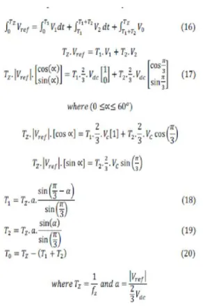
At sector I, V1 and V2 are voltage vectors. Assume Vrefmakes ‘α’ phase angle difference with V1. This Vref can be calculated using vector calculus by referring Fig.9. Tz is the switching time interval at which output voltage of inverter is constant. T1and T2 are switching time duration of voltage space vectors V1and V2.
Fig.9. Reference Vector with Respect to Sector I
E. Switching Time at Any Duration (T1, T2,
T0)
Switching time at any instant can be illustrated here. For n number of samples T1, T2 and T0 are,
where n=1 through 6 (that is sector 1 to 6), 0≤ α≤ 600
F. Switching Time
Table 2 shows the six sectors and the time calculation of each switch. This can be easily calculated using the switching states.
TABLE 2
SWITCHING TIME CALCULATION AT EACH SECTOR
V. SIMULATION RESULTS
Output voltage of PV panel is a low voltage DC, which is given to the inverter through a z source network. Inverter boosts this voltage by shoot-through-mode and converts the DC voltage into AC voltage. This conversion is done with the help of the inverter based on SVPWM. The inverter has MOSFET switches which are switched by the SVPWM. The universal bridge inverter converting the DC to AC three phase voltage by using the space vector pulse width modulation from the SVPWM generator. This circuit takes the reference voltage from the three phase inverter output. The Z-source inductor and capacitors are act as a filter and they generate resonant to the switches. Output voltage obtained three phase AC which is given to the grid or to the load. Obtaining AC contains ripples which are filtered by LC filter. The battery is connected in parallel with the capacitor C1. This circuit is analyzed in the SIMULINK software. The simulation circuit is shown in the Fig.10.
E. Switching Time at Any Duration (T1, T2,
T0)
Switching time at any instant can be illustrated here. For n number of samples T1, T2 and T0 are,
where n=1 through 6 (that is sector 1 to 6), 0≤ α≤ 600
F. Switching Time
Table 2 shows the six sectors and the time calculation of each switch. This can be easily calculated using the switching states.
TABLE 2
SWITCHING TIME CALCULATION AT EACH SECTOR
V. SIMULATION RESULTS
Fig.10. Quasi Z-Source Inverter using PV Module
Fig.11 Input voltage waveform
Fig.12 Output Voltage Waveforms
VI. CONCLUSIONS
In this paper, a novel topology for energy stored QZSI has been proposed to overcome the shortcoming of the existing solutions in PV power system. The theoretical analysis, simulations results presented in this work clearly demonstrate the proposed energy-stored QZSI with SVPWM technique. QZSI used for solar power applications, where both boosting and inverting can be done in a single stage. The battery operation can balance the fluctuations from PV panel and supply the continuous power to the grid/load, whenever PV panel cannot generate the power due to some low irradiation. There are three power sources i.e., PV panels, battery and the grid/load. Controlling the two power flow, the third one automatically matches the power difference. The proposed energy stored QZSI have some new advantages more suitable for application in
PV systems. This will make the PV system simpler and lower cost.
References
[1] Vinnikov.D and IndrekRoasto (2011) ‘Quasi -Z-Source-Based Isolated DC/DC Converters for Distributed Power Generation’, IEEE Transactions on industrial electronics, vol. 58, no.1.
[2] Aeenmehr.A, Sina.A and Mohamadian.H (2012) ‘Power System Voltage Control using LP and Artificial Neural Network’, World Academy of Science, Engineering and Technology
[3] Eung-Ho Kim and Jong-Jae Lee (2008) ‘Dual Series-Resonant Active-Clamp Converter IEEE Trans. On Industrial Electronics’, Vol. 55, No. 2,699.
[4] Fang ZhengPeng and MiaosenShen (2008) ‘Operation Modes and Characteristics of the Z -Source Inverter With Small Inductance or Low Power Factor’, IEEE Trans. On Industrial Electronics, Vol. 55, No.1. [5] Fausett.L (1994) ‘Fundamentals of Neural Networks Architectures Algorithm and applications”, Printice Hall International
[6] Fang ZhengPeng (2003) ‘Z-Source Inverter’, IEEE Trans.On Industry Applications, Vol. 39, No. 2.
[7] J.ZakisD,Vinnikov.D,I..Roasto (2010) ‘Softswitching capability analysis of a qZSIbased DC/DC converter’12th Biennial Baltic Electronics Conference (BEC2010) .
[8] Heung-Geun Kim, Jong-Hyoung Park (2012) ‘Power Conditioning System for a Grid Connected PV Power Generation Using a Quasi-Z-Source Inverter’, On JPE 10-2K12
[9] Jin Wang, Joel Anderson and Ryan Buffenbarger (2004) ‘Low Cost Fuel Cell Converter System for Residential Power Generation’, IEEE Trans. On Power Electronics, Vol. 19, No. 5.
[10]Kamaraj.V, ShajithAli.U (2011) ‘Z-Source Inverter with A New Space Vector PWM Algorithm For high Voltage Gain’, ISSN1819-6608 Vol. 6,NO. 6.
Fig.10. Quasi Z-Source Inverter using PV Module
Fig.11 Input voltage waveform
Fig.12 Output Voltage Waveforms
VI. CONCLUSIONS
In this paper, a novel topology for energy stored QZSI has been proposed to overcome the shortcoming of the existing solutions in PV power system. The theoretical analysis, simulations results presented in this work clearly demonstrate the proposed energy-stored QZSI with SVPWM technique. QZSI used for solar power applications, where both boosting and inverting can be done in a single stage. The battery operation can balance the fluctuations from PV panel and supply the continuous power to the grid/load, whenever PV panel cannot generate the power due to some low irradiation. There are three power sources i.e., PV panels, battery and the grid/load. Controlling the two power flow, the third one automatically matches the power difference. The proposed energy stored QZSI have some new advantages more suitable for application in
PV systems. This will make the PV system simpler and lower cost.
References
[1] Vinnikov.D and IndrekRoasto (2011) ‘Quasi -Z-Source-Based Isolated DC/DC Converters for Distributed Power Generation’, IEEE Transactions on industrial electronics, vol. 58, no.1.
[2] Aeenmehr.A, Sina.A and Mohamadian.H (2012) ‘Power System Voltage Control using LP and Artificial Neural Network’, World Academy of Science, Engineering and Technology
[3] Eung-Ho Kim and Jong-Jae Lee (2008) ‘Dual Series-Resonant Active-Clamp Converter IEEE Trans. On Industrial Electronics’, Vol. 55, No. 2,699.
[4] Fang ZhengPeng and MiaosenShen (2008) ‘Operation Modes and Characteristics of the Z -Source Inverter With Small Inductance or Low Power Factor’, IEEE Trans. On Industrial Electronics, Vol. 55, No.1. [5] Fausett.L (1994) ‘Fundamentals of Neural Networks Architectures Algorithm and applications”, Printice Hall International
[6] Fang ZhengPeng (2003) ‘Z-Source Inverter’, IEEE Trans.On Industry Applications, Vol. 39, No. 2.
[7] J.ZakisD,Vinnikov.D,I..Roasto (2010) ‘Softswitching capability analysis of a qZSIbased DC/DC converter’12th Biennial Baltic Electronics Conference (BEC2010) .
[8] Heung-Geun Kim, Jong-Hyoung Park (2012) ‘Power Conditioning System for a Grid Connected PV Power Generation Using a Quasi-Z-Source Inverter’, On JPE 10-2K12
[9] Jin Wang, Joel Anderson and Ryan Buffenbarger (2004) ‘Low Cost Fuel Cell Converter System for Residential Power Generation’, IEEE Trans. On Power Electronics, Vol. 19, No. 5.