Analysis Of Seven Level Asymmetric Cascaded H-Bridge Inverter
1
M. Manga lakshmi ,2G.D.Sairam vihari,3T.Venkata parasuram 1
Assistant Professor , 2,3B.Tech student Department of EEE, Pragati Engineering College
Surampalem, AP
[email protected], [email protected] [email protected]
Abstract:
The cascaded multilevel inverter (CMLI) has gained much attention in recent years due to its advantages in high voltage and high power with low harmonics applications. A standard cascaded multilevel inverter requires n DC sources for 2n+1levels at the output,
where ‘n’ is the number of inverter stages. This
project presents a topology to control cascaded multilevel inverter that is implemented with multiple DC sources to get 2n+1-1 levels. Without using Pulse Width Modulation (PWM) technique, the firing circuit can be implemented using Microcontroller which greatly reduces the Total Harmonic Distortion (THD) and switching losses. The model of a cascaded hybrid multilevel inverter is developed with software simulation using MATLAB/SIMULINK software.
Introduction
Power electronic converters, especially DC/AC PWM inverters have been extending their range of use in industry because they provide reduced energy consumption, better system efficiency, improved quality of product, good maintenance, and so on. For a medium voltage grid, it is troublesome to connect only one power semiconductor switches directly. As a result, a multilevel power converter structure has been introduced as an alternative in high power and medium voltage situations such as laminators, mills, conveyors, pumps, fans, blowers, compressors, and so on. As a cost effective solution, multilevel converter not only achieves high power ratings, but also enables the use of low power application in renewable energy sources such as photovoltaic, wind, and fuel cells which can be easily interfaced to a multilevel converter system for a high power application. The most common initial application of multilevel converters has been in traction, both in locomotives and track -side static converters. More recent applications have been for power system converters for VAR compensation and stability enhancement, active filtering, high-voltage motor drive, high-high-voltage dc transmission,
and most recently for medium voltage induction motor variable speed drives. Many multilevel converter applications focus on industrial medium-voltage motor drives, utility interface for renewable energy systems, flexible AC transmission system (FACTS), and traction drive systems.
The inverters in such application areas as stated above should be able to handle high voltage and large power. For this reason, two-level high-voltage and large-power inverters have been designed with series connection of switching power devices such as gate -turn-off thyristors (GTOs), integrated gate commutated transistors (IGCTs), and integrated gate bipolar transistors (IGBTs), because the series connection allows reaching much higher voltages. However , the series connection of switching power devices has big problems, namely, non equal distribution of applied device voltage across series-connected devices that may make the applied voltage of individual devices much higher than blocking voltage of the devices during transient and steady-state switching operation of devices.
H–Bridge Inverter
“H” topology has many redundant
combinations of switches’ positions to produce the same voltage levels. As an example, the level “zero”
can be generated with switches in position S(1) and S(2), or S(3) and S(4), or S(5) and S(6), and so on.
Another characteristic of “H” converters is
that they only produce an odd number of levels, which
ensures the existence of the “0V” level at the load .For
example, a 51-level inverter using an “H”
International Journal of Science Engineering and Advance Technology,
IJSEAT, Vol 3, Issue 9
ISSN 2321-6905
September-2015
cascaded inverter does not require any voltage-clamping diodes or voltage balancing capacitors.
This configuration is useful for constant frequency applications such as active front-end rectifiers, active power filters, and reactive power compensation. In this case, the power supply could also be voltage regulated dc capacitor. The circuit diagram consists of two cascade bridges. The load is connected in such a way that the sum of output of these bridges will appear across it. The ratio of the power supplies between the auxiliary bridge and the main bridge is 1:3. One important characteristic of multilevel converters using voltage escalation is that electric power distribution and switching frequency present advantages for the implementation of these topologies.
The full-bridge topology is used to synthesize a three-level square-wave output waveform. The half-bridge and full-bridge configurations of the single-phase voltage source inverter are shown in Fig.1 and 2, respectively. In a single-phase half-bridge inverter, only two switches are needed.
To avoid shoot-through fault, both switches are never turned on at the same time. S1 is turned on and S2 is turned off to give a load voltage, VAOin Fig.2, of +V
s/2 . To complete one cycle, S1 is turned off and S2 is turned on to give a load voltage, VAO, of -V s/2. In full
bridge configuration, turning on S1 and S4 and turning off S2 and S3 give a voltage of VS between
point A and B (VAB) in Fig.2 while turning off S1 and
S4 and turning on S2 and S3 give a voltage of -Vs .
Fig.1 Half bridge inverter
Fig.2 Full Bridge Inverter
To generate zero level in a full-bridge inverter, the combination can be S1 and S2 on while S3 and S4 off or vice versa. The three possible levels referring to above discussion are shown in Table
Conducing Switches Load Voltage VAB
S1,S4 +Vs
S2,S3 -Vs
S1,S4or S2,S3 0
Switching pattern of full bridge inverter
Note that S1 and S3 should not be closed at the same time, nor should S2 and S4. Otherwise, a short circuit would exist across the dc source. The output waveform of half bridge and full-bridge of single-phase voltage source inverter are shown in Fig.
Output waveform of Half Bridge Inverter
Output waveform of Full Bridge Inverter
Classification of Multilevel Inverters:
Clamped Multilevel Inverter and the Flying Capacitor inverter comes under the category of Single DC source where the input supply is taken from a single DC source.
Diode-Clamped Multilevel Inverter
The most commonly used multilevel topology is the diode clamped inverter, in which the diode is used as the clamping device to clamp the dc bus voltage so as to achieve steps in the output voltage. A three-level diode clamped inverter consists of two pairs of switches and two diodes. Each switch pairs works in complimentary mode and the diodes used to provide access to mid-point voltage. In a three-level inverter each of the three phases of the inverter shares a common dc bus, which has been subdivided by two capacitors into three levels. The DC bus voltage is split into three voltage levels by using two series connections of DC capacitors,C1 and C2. The voltage stress across each switching device is limited to Vdc through the clamping diodes Dc1 and Dc2. It is assumed that the total dc link voltage is Vdc and mid point is regulated at half of the dc link voltage, the voltage across each capacitor is Vdc/2 (Vc1=Vc2=Vdc/2). In a three level diode clamped inverter, there are three different possible switching states which apply the stair case voltage on output voltage relating to DC link capacitor voltage rate. For a three-level inverter, a set of two switches is on at any given time and in a five-level inverter, a set of four switches is on at any given time and so on. Fig shows the circuit for a diode clamped inverter for a three-level and a five-level inverter.
Switching pattern of Diode-Clamped Multilevel Inverter
Fig shows the phase voltage and line voltage of the three-level inverter in the balanced condition. The line voltage Vab consists of a phase-leg a voltage and a phase-leg b voltage. The resulting line voltage is a 5-level staircase waveform for three-level inverter and 9-level staircase waveform for a five-level inverter. This means that an N-level diode-clamped inverter has an N-level output phase voltage and a (2N-1)-level output line voltage.
Topology of the diode-clamped inverter (a) three-level inverter, (b) five -three-level inverter
In general the voltage across each capacitor for an N level diode clamped inverter at steady state is Vdc/ (N-1). Although each active switching device is required to block only a voltage level of Vdc, the clamping diodes require different ratings for reverse voltage blocking
Output voltage in three-level diode- clamped inverter (a) leg voltage(b) output phase voltage
In general for an N level diode clamped inverter, for each leg 2(N-1) switching devices, (N-1) * (N-2) clamping diodes and (N-1) dc link capacitors are required. By increasing the number of voltage levels the quality of the output voltage is improved and the voltage waveform becomes closer to sinusoidal waveform. However, capacitor voltage balancing will be the critical issue in high level inverters. When N is sufficiently high, the number of diodes and the number of switching devices will increase and make the system impracticable to implement. If the inverter runs under pulse width modulation (PWM), the diode reverse recovery of these clamping diodes becomes the major design challenge.
Flying-Capacitor Multilevel Inverter:
International Journal of Science Engineering and Advance Technology,
IJSEAT, Vol 3, Issue 9
ISSN 2321-6905
September-2015
each capacitor differs from that of the next capacitor. To generate m-level staircase output voltage, m-1 capacitors in the dc bus are needed. Each phase-leg has an identical structure. The size of the voltage increment between two capacitors determines the size of the voltage levels in the output waveform.
Five level Flying capacitor MLI
In fact, there is more than one combination to produce output voltages V2, V3, and V4. That makes the FCMI more flexibility than DCMI. Table shows only one possible combination.
Switching States of Five level Capacitor MLI
Cascaded H-Bridge Multilevel Inverter:
The cascaded H-bridge multilevel Inverter uses separate dc sources (SDCSs). The multilevel inverter using cascaded-inverter with SDCSs synthesizes a desired voltage from several independent sources of dc voltages, which may be obtained from batteries, fuel cells, or solar cells. This configuration recently becomes very popular in ac power supply and adjustable speed drive applications. This new inverter can avoid extra clamping diodes or voltage balancing capacitors. Again, the cascaded multilevel inverters are classified depending on the type of DC sources used throughout the input.
A single-phase structure of an m-level cascaded inverter is Each separate dc source (SDCS) is connected to a single-phase full-bridge, or H-bridge, inverter. Each inverter level can generate three different voltage outputs, +V
dc, 0, and –Vdc by connecting the dc source to the ac output by different combinations of the four switches, S
1, S2, S3, and S4. To obtain +V
dc, switches S1and S4 are turned on, whereas–V
dccan be obtained by turning on switches S
2and S3. By turning on S1and S2or S3and S4, the output voltage is 0. The ac outputs of each of the different full-bridge inverter levels are connected in
series such that the synthesized voltage waveform is the sum of the inverter outputs.
Single phase structures of Cascaded inverter (a) 3-level, (b)5-3-level, (c) 7-level
One more alternative for a multilevel inverter is the cascaded multilevel inverter or series H-bridge inverter. The series H-bridge inverter appeared in 1975. Cascaded multilevel inverter was not fully realized until two researchers, Lai and Peng. They patented it and presented its various advantages in 1997. Since then, the CMI has been utilized in a wide range of applications. With its modularity and flexibility, the CMI shows superiority in high-power applications, especially shunt and series connected FACTS controllers. The CMI synthesizes its output
nearly sinusoidal voltage waveforms by combining many isolated voltage levels. By adding more H-bridge converters, and build-in redundancy against individual H-bridge converter failure can be realized. A series of single-phase full bridges makes up a phase for the inverter. A three-phase CMI topology is essentially composed of three identical phase legs of the series-chain of H-bridge converters, which can possibly generate different output voltage waveforms and offers the potential for AC system phase-balancing. This feature is impossible in other VSC topologies utilizing a common DC link. Since this topology consists of series power conversion cells, the voltage and power level may be easily scaled. The dc link supply for each full bridge converter is provided separately, and this is typically achieved using diode
Output VAO
Switch state
Sa1 Sa2 Sa3 Sa4 Sa1’ Sa2’ Sa3’ Sa4’
V5=Vdc 1 1 1 1 0 0 0 0
V4=3Vdc /4 1 1 1 0 1 0 0 0
V3=Vdc/2 1 1 0 0 1 1 0 0
V2=Vdc/4 1 0 0 0 1 1 1 0
rectifiers fed from isolated secondary windings of a three-phase transformer..
Seven level CMLI:
The converter topology is based on the series connection of single-phase inverters with separate dc sources. Fig. shows the power circuit for one phase leg of a three-level , five-level and seven-level cascaded inverter. The resulting phase voltage is synthesized by the addition of the voltages generated by the different cells. In a 3-level cascaded inverter each single-phase full-bridge inverter generates three voltages at the output: +Vdc, 0, -Vdc (zero, positive dc voltage, and negative dc voltage). This is made possible by connecting the capacitors sequentially to the ac side via the power switches. The resulting output ac voltage swings from -Vdc to +Vdc with three levels, 2Vdc to +2Vdc with fivelevel and -3Vdc to +-3Vdc with seven-level inverter. The staircase waveform is nearly sinusoidal, even without filtering.
Features of CMLI:
For real power conversions, (ac to dc and dc to ac), the cascaded-inverter needs separate dc sources. The structure of separate dc sources is well suited for various renewable energy sources such as fuel cell, photovoltaic, and biomass, etc.
Connecting separated dc sources between two converters in a back-to-back fashion is not possible because a short circuit will be introduced when two back-to-back converters are not switching synchronously.
Symmetrical Cascaded H-Bridge Multilevel
Inverter:
If all the input sources are of equal magnitude, it is known as Symmetrical H-Bridge inverter as shown in fig and the switching sequence is given in table. Here both the full bridge inverters are fed with different sources of equal magnitude.
Symmetrical five level Cascaded H-Bridge inverter
In the above fig, each SDCS of equal magnitude is associated with a single-phase full-bridge inverter. The ac terminal voltages of different level inverters are connected in series. By different combinations of the four switches, S1-S4, each inverter level can generate three different voltage outputs, +Vdc, -Vdc, and zero. The ac output of each of the different level of full-bridge inverters are connected in series such that the synthesized voltage waveform is the sum of the inverter outputs. In this topology, the number of output phase voltage levels is defined by m = 2s+1, where s is the number of dc sources.
A 5-level cascaded-inverters will have two SDCSs and two full-bridge cells. The switching table for the five level cascaded inverter is shown below. Here, 2 Full Bridges are used and are cascaded to each other. The Switches S1, S2, S3,and S4 are from upper H-Bridge and Switches S5 S6 S7 and S8 are from lower H-Bridge .By giving correct switching patter n ,we get 5 voltage levels i.e. 2Vdc,Vdc,0,-2Vdc,- Vdc, S1,S2,S5,D7 are on .To get 2Vdc, S1,S2,S6,S5 are kept on .The switching table is shown below to get 5 levels with a Symmetrical DC source
Switches ON Voltage level
S1, S2, S5 and D7 Vdc/2 S1, S2, S6and S5 Vdc S1, S2, S6 and D8 Vdc/2 S1, D3, S6 and D8 0 S3, S4, S6 and D8 -Vdc/2 S3, S4, S7 and S8 -Vdc S3, S4, D6 and S8 -Vdc/2 S1, S3, D6 and S8 0
Switching states of Symmetrical five level cascaded H-Bridge inverter
Output waveform of Symmetrical Cascaded H-Bridge multilevel Inverter
Asymmetrical Cascaded H-Bridge Multilevel Inverter:
The cascaded H-Bridge multilevel inverter with two SDCS with unequal magnitude is known as Asymmetrical Cascaded H-Bridge multilevel Inverter. The following is figure of Asymmetrical Cascaded H-Bridge multilevel Inverter where it is having 2 unequal DC sources +2Vdc/3 and rectifiers fed from isolated secondary windings of a
three-phase transformer..
Seven level CMLI:
The converter topology is based on the series connection of single-phase inverters with separate dc sources. Fig. shows the power circuit for one phase leg of a three-level , five-level and seven-level cascaded inverter. The resulting phase voltage is synthesized by the addition of the voltages generated by the different cells. In a 3-level cascaded inverter each single-phase full-bridge inverter generates three voltages at the output: +Vdc, 0, -Vdc (zero, positive dc voltage, and negative dc voltage). This is made possible by connecting the capacitors sequentially to the ac side via the power switches. The resulting output ac voltage swings from -Vdc to +Vdc with three levels, 2Vdc to +2Vdc with fivelevel and -3Vdc to +-3Vdc with seven-level inverter. The staircase waveform is nearly sinusoidal, even without filtering.
Features of CMLI:
For real power conversions, (ac to dc and dc to ac), the cascaded-inverter needs separate dc sources. The structure of separate dc sources is well suited for various renewable energy sources such as fuel cell, photovoltaic, and biomass, etc.
Connecting separated dc sources between two converters in a back-to-back fashion is not possible because a short circuit will be introduced when two back-to-back converters are not switching synchronously.
Symmetrical Cascaded H-Bridge Multilevel
Inverter:
If all the input sources are of equal magnitude, it is known as Symmetrical H-Bridge inverter as shown in fig and the switching sequence is given in table. Here both the full bridge inverters are fed with different sources of equal magnitude.
Symmetrical five level Cascaded H-Bridge inverter
In the above fig, each SDCS of equal magnitude is associated with a single-phase full-bridge inverter. The ac terminal voltages of different level inverters are connected in series. By different combinations of the four switches, S1-S4, each inverter level can generate three different voltage outputs, +Vdc, -Vdc, and zero. The ac output of each of the different level of full-bridge inverters are connected in series such that the synthesized voltage waveform is the sum of the inverter outputs. In this topology, the number of output phase voltage levels is defined by m = 2s+1, where s is the number of dc sources.
A 5-level cascaded-inverters will have two SDCSs and two full-bridge cells. The switching table for the five level cascaded inverter is shown below. Here, 2 Full Bridges are used and are cascaded to each other. The Switches S1, S2, S3,and S4 are from upper H-Bridge and Switches S5 S6 S7 and S8 are from lower H-Bridge .By giving correct switching patter n ,we get 5 voltage levels i.e. 2Vdc,Vdc,0,-2Vdc,- Vdc, S1,S2,S5,D7 are on .To get 2Vdc, S1,S2,S6,S5 are kept on .The switching table is shown below to get 5 levels with a Symmetrical DC source
Switches ON Voltage level
S1, S2, S5 and D7 Vdc/2 S1, S2, S6and S5 Vdc S1, S2, S6 and D8 Vdc/2 S1, D3, S6 and D8 0 S3, S4, S6 and D8 -Vdc/2 S3, S4, S7 and S8 -Vdc S3, S4, D6 and S8 -Vdc/2 S1, S3, D6 and S8 0
Switching states of Symmetrical five level cascaded H-Bridge inverter
Output waveform of Symmetrical Cascaded H-Bridge multilevel Inverter
Asymmetrical Cascaded H-Bridge Multilevel Inverter:
International Journal of Science Engineering and Advance Technology,
IJSEAT, Vol 3, Issue 9
ISSN 2321-6905
September-2015
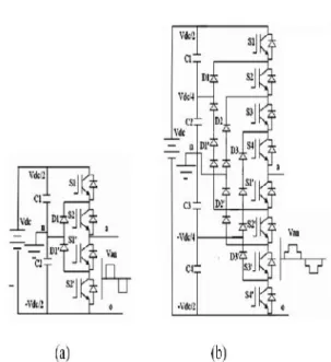
+Vdc/3.
Asymmetrical Cascaded H-Bridge multilevel Inverter
By using this type of Asymmetrical
configuration, for a ‘n’ bridge inverter we can get
3n+1 voltage levels and n Capacitors of each rating nVdc/(n+1), Vdc/(n+1) to get Vdc max and 6n switches of each voltage rating is Vdc/(n+1).The following is the switching table of Asymmetrical Cascaded H-Bridge multilevel Inverter.
Switches ON Voltage level
S4, S2, S5 and S6 Vdc/3
S1, S2, S8 and S6 2Vdc/3
S1, S2, S5and S6 Vdc
S4, S2, S7 and S8 -Vdc/3
S3, S4, S6 and S8 -2Vdc/3
S3, S4, S7 and S8 -Vdc
S4, S2, S8 and S6 0
Switching states of Asymmetrical five level cascaded H-Bridge inverter
The multilevel inverter of Fig. utilizes two independent DC sources and consequently will create an output phase voltage with seven levels. N is the number of independent DC sources per phase, m is the number of levels, I is the number of switches with freewheeling diodes per phase, then the following equations are applied for CMLI
m=2n+1, l=2(m-1) A simplified
single phase topology is shown in Fig. The output voltage will be + IOV (top inverter HI) when switches TIl and TI4 conducts. Similarly -IOV will be obtained when T12and T13conducts. The output voltage is +20V only when T21 and T24 are
conducting and the output voltage is -20V only when T22 and T23 are conducting. The output voltage +30V is available when switches Tl1 ,T14 ,T21 and T24 conducts and -30V is available when switches TI2,T13,T22 and T23 conducts.
Conduction Table for CMLI
vdc vdc V out 12v 24v T11 T21 T12 T13 T14 T23 T22 T24
Power circuit of CMLI
Components Ratings: Power Circuit:
Transformers-36VA(12-0-12V,3A) Filtering Capacitors-63V,1000MicroFarads Diode-1N4007(If=1A,Vf=1.1V,IR=5e-6A) Diode-DO4(If=6A, Vf=1.1)
Control Circuit:
MicroController-AT89S52 Transformer-12VA(12-0-12V,1A) Diode-1N4007(If=1A,Vf=1.1V,IR=5e-6A) Filtering Capacitor-25V,1000MicroFarads Voltage Regulator-IC 7805C(Input
voltages:Vmin=5V,Vmax=25V;Output Voltages: Vmin=4.8V, Vmax=5.2V) Crystal
Oscillator-11.0592MHz(C1=C2=33PicoFarads,Rs=100o hms)
Reset-(C=50V,10MicroFarads,R=4200ohms)
International Journal of Science Engineering and Advance Technology,
IJSEAT, Vol 3, Issue 9
ISSN 2321-6905
September-2015
+Vdc/3.
Asymmetrical Cascaded H-Bridge multilevel Inverter
By using this type of Asymmetrical
configuration, for a ‘n’ bridge inverter we can get
3n+1 voltage levels and n Capacitors of each rating nVdc/(n+1), Vdc/(n+1) to get Vdc max and 6n switches of each voltage rating is Vdc/(n+1).The following is the switching table of Asymmetrical Cascaded H-Bridge multilevel Inverter.
Switches ON Voltage level
S4, S2, S5 and S6 Vdc/3
S1, S2, S8 and S6 2Vdc/3
S1, S2, S5and S6 Vdc
S4, S2, S7 and S8 -Vdc/3
S3, S4, S6 and S8 -2Vdc/3
S3, S4, S7 and S8 -Vdc
S4, S2, S8 and S6 0
Switching states of Asymmetrical five level cascaded H-Bridge inverter
The multilevel inverter of Fig. utilizes two independent DC sources and consequently will create an output phase voltage with seven levels. N is the number of independent DC sources per phase, m is the number of levels, I is the number of switches with freewheeling diodes per phase, then the following equations are applied for CMLI
m=2n+1, l=2(m-1) A simplified
single phase topology is shown in Fig. The output voltage will be + IOV (top inverter HI) when switches TIl and TI4 conducts. Similarly -IOV will be obtained when T12and T13conducts. The output voltage is +20V only when T21 and T24 are
conducting and the output voltage is -20V only when T22 and T23 are conducting. The output voltage +30V is available when switches Tl1 ,T14 ,T21 and T24 conducts and -30V is available when switches TI2,T13,T22 and T23 conducts.
Conduction Table for CMLI
vdc vdc V out 12v 24v T11 T21 T12 T13 T14 T23 T22 T24
Power circuit of CMLI
Components Ratings: Power Circuit:
Transformers-36VA(12-0-12V,3A) Filtering Capacitors-63V,1000MicroFarads Diode-1N4007(If=1A,Vf=1.1V,IR=5e-6A) Diode-DO4(If=6A, Vf=1.1)
Control Circuit:
MicroController-AT89S52 Transformer-12VA(12-0-12V,1A) Diode-1N4007(If=1A,Vf=1.1V,IR=5e-6A) Filtering Capacitor-25V,1000MicroFarads Voltage Regulator-IC 7805C(Input
voltages:Vmin=5V,Vmax=25V;Output Voltages: Vmin=4.8V, Vmax=5.2V) Crystal
Oscillator-11.0592MHz(C1=C2=33PicoFarads,Rs=100o hms)
Gate Circuit:
MOSFET-IRF540,N-CHANNEL
MOSFET(VDS=100V,VGS=10V,RDS0.077oh ms,ID=28A)
Transformers-6VA(12-0-12V,0.5A) Gate Resistor-1000ohms
Diode-1N4007(If=1A,Vf=1.1V,IR=5e-6A) Filtering Capacitors-25V,1000MicroFarads
RESULTS AND DISCUSSION
The proposed inverter is simulated by using MATLAB/ SIMULINK. The asymmetrical DC voltages, 20V and 40 V are applied at the input side of the H Bridge inverter. The voltage steps in the outputs are therefore 0V, 20V, 40V, 60V,-20V,-40V and-60V.
Software Simulation of Asymmetric Cascaded H Bridge Seven level Inverter
using MATLAB/SIMULINK
Output voltage of seven level inverter in Software Simulation
Conclusion:
The cascaded multilevel inverter (CMLI) is developed with software simulation using MATLAB/SIMULINK software. In this project, digital switching scheme is employed for Asymmetric Cascaded H Bridge Seven level Inverter and the advantage of using digital scheme is that it reduces the uneven degradation of power switches, switching losses when compared to the conventional PWM technique and harmonics are also reduced. From the Simulation results, the Total harmonic distortion of inverter is 16.92% which can be reduced by increasing the number of stages of inverter also. Consequently, the system efficiency can be improved. This proposed system eliminates the complexity of generating gate signals when the stages are added. The simulation results show that this hybrid multilevel inverter topology can be applied for high power applications.
REFERENCES
[1] S.Albert Alexander, T.Manigandan, N.Senthilnathan ,"Digital Switching Scheme for Cascaded Multilevel Inverters" Third International Conference on Power Systems, Kharagpur, INDIA December 27-29,2009.
[2] Keith A. Corzine, Mike W. Wielebski, Fang Z. Peng,and Jin Wang, "Control of Cascaded Multilevel Inverters" on power electronics May 2004.
[3] L.M.Tolbert, F.z.Peng and T.G.Habetler, "Multilevel converters for Large Electric Drives," IEEE Transactions on Industry Applications, vol. 35,no.5,pp.36-44,JanuarylFebruary 1999.
[4] Jose Rodriguez,Steffen Bernet and BinWu, "Multilevel voltage source converter topologies for Industrial medium voltage Drives," IEEE Transactions on Industrial Electronics,voI.54, no.6,pp.2930-2945, December 2007.
[5] F.Huang,"Near optimal approach in the design and implementation of multilevel voltage source inverter", lEEE -Proc -Electr Power Appl.,VoI 146,No 6, pp. 661-666, November 1999.
[6] Yu Liu, Hoon Hong, and Alex Q. Huang, "Real Time algorithm for minimising THD in multilevel inverters using unequal or varying voltage steps under stair case modulation", IEEE Transactions on Industrial Electronics, vol. 56,no.6, pp. 2249-2258, June 2009.
[7]A text book in”Power Electronics” by M.D.Singh