DigitalCommons@University of Nebraska - Lincoln
Computer Science and Engineering: Theses,
Dissertations, and Student Research Computer Science and Engineering, Department of
Fall 10-25-2018
Optical Wireless Data Center Networks
Abdelbaset S. Hamza
University of Nebraska - Lincoln, [email protected]
Follow this and additional works at:http://digitalcommons.unl.edu/computerscidiss
Part of theComputer Sciences Commons,Digital Communications and Networking Commons, and theSystems and Communications Commons
This Article is brought to you for free and open access by the Computer Science and Engineering, Department of at DigitalCommons@University of Nebraska - Lincoln. It has been accepted for inclusion in Computer Science and Engineering: Theses, Dissertations, and Student Research by an authorized administrator of DigitalCommons@University of Nebraska - Lincoln.
Hamza, Abdelbaset S., "Optical Wireless Data Center Networks" (2018).Computer Science and Engineering: Theses, Dissertations, and Student Research. 158.
by
Abdelbaset S. Hamza
A DISSERTATION
Presented to the Faculty of
The Graduate College at the University of Nebraska In Partial Fulfillment of Requirements
For the Degree of Doctoral of Philosophy
Major: Engineering
Under the Supervision of Professors Jitender S. Deogun and Dennis R. Alexander
Lincoln, Nebraska
Abdelbaset S. Hamza, Ph.D. University of Nebraska, 2018
Advisors: Jitender S. Deogun and Dennis R. Alexander
Bandwidth and computation-intensive Big Data applications in disciplines like so-cial media, bio- and nano-informatics, Internet-of-Things (IoT), and real-time analyt-ics, are pushing existing access and core (backbone) networks as well as Data Center Networks (DCNs) to their limits. Next generation DCNs must support continuously increasing network traffic while satisfying minimum performance requirements of la-tency, reliability, flexibility and scalability. Therefore, a larger number of cables (i.e., copper-cables and fiber optics) may be required in conventional wired DCNs. In addi-tion to limiting the possible topologies, large number of cables may result into design and development problems related to wire ducting and maintenance, heat dissipation, and power consumption.
To address the cabling complexity in wired DCNs, we propose OWCells, a class of optical wireless cellular data center network architectures in which fixed line of sight (LOS) optical wireless communication (OWC) links are used to connect the racks arranged in regular polygonal topologies. We present the OWCell DCN architecture, develop its theoretical underpinnings, and investigate routing protocols and OWC transceiver design. To realize a fully wireless DCN, servers in racks must also be connected using OWC links. There is, however, a difficulty of connecting multiple adjacent network components, such as servers in a rack, using point-to-point LOS links. To overcome this problem, we propose and validate the feasibility of an FSO-Bus to connect multiple adjacent network components using NLOS point-to-point
To complete the design of the OWC transceiver, we develop a new class of strictly and rearrangeably non-blocking multicast optical switches in which multicast is per-formed efficiently at the physical optical (lower) layer rather than upper layers (e.g., application layer).
Acknowledgements
First and foremost, I would like to thank my parents for their endless support, love, and sincere prayers. Without their love and support, this dissertation would not have been completed. I heartily thank Mohammed, Haitham, Kamal, Faisal, and Abdelrahman for their love and support. They are not only great brothers, but also my true friends.
Special thanks to my advisors Prof. Jitender Deogun and Prof. Dennis Alexander. Their keen insights, support, patience, and the strong belief in my capability played a key role in building this work.
I would like to thank Prof. Lily Wang and Prof. Lisong Xu for serving on my Ph.D. committee.
Special thanks to Prof. Jerry L. Hudgins and Prof. Sohrab Asgarpoor for offering me the exciting opportunity of teaching the ELEC 370/CSCE 335 and ELEC 211 courses. This experience was crucial for shaping my teaching skills and philosophy.
I would like to thank my dear and best friends Ahmed Abdelraheem and Be-ligh Ben Taleb for their continuous support. They taught me the true meaning of friendship.
Finally, I would like to convey my appreciation to the Makkawy’s for their support during my stay in Lincoln. Special thanks to Karim Makkawy, Amin Makkawy, and Hatem Kittana.
Contents
1 Introduction 1
1.1 Dissertation Outline . . . 9
2 Optical Wireless Communication (OWC) Technology 11 2.1 Introduction . . . 12
2.1.1 Motivation and Contribution . . . 16
2.1.2 Chapter Organization . . . 18
2.2 Preliminaries and Basic Concepts . . . 19
2.2.1 Naming Convention - FSO vis-`a-vis OWC . . . 19
2.2.2 Light Sources . . . 20
2.2.3 Photodetectors . . . 21
2.2.4 Modulation . . . 22
2.3 Existing Classifications and Surveys of FSO Links . . . 24
2.4 Proposed Framework for FSO Link Classification . . . 32
2.4.1 Elements of the Proposed Classification . . . 33
2.4.2 The Proposed Classification . . . 36
2.5 Indoor FSO Links . . . 41
2.5.1 Indoor FSO Link Configurations . . . 41
2.5.2 Impairments of Indoor FSO Links . . . 49
2.5.3 Indoor FSO Standards and Recommendations . . . 52
2.6 Terrestrial FSO Links . . . 57
2.6.1 Terrestrial FSO Link Configurations . . . 58
2.6.2 Impairments of Terrestrial FSO Links . . . 65
2.6.3 Terrestrial FSO Standards and Recommendations . . . 68
2.7 Space FSO Links . . . 71
2.7.1 Space FSO Link Configurations . . . 72
2.7.2 Impairments of Space FSO Links . . . 72
2.7.3 Space FSO Standards and Recommendations . . . 73
2.8 Underwater FSO Links . . . 74
2.8.1 Underwater FSO Link Configurations . . . 76
2.8.2 Impairments of UOWC Links . . . 82
2.8.3 Underwater FSO Standards and Recommendations . . . 83
2.9.2 Space-Air/Ground Links ({S−T}/P C/LOS/x/U Long) . . . 84
2.10 Classification of FSO Systems Using the Proposed Framework . . . . 89
2.10.1 Heterogenous FSO Systems . . . 90
2.10.2 Hybrid FSO Systems . . . 91
2.10.3 Case Study: LiFi-Based Systems . . . 94
2.11 Summary . . . 94
3 Wireless Data Center Networks 97 3.0.1 Motivation and Scope . . . 97
3.1 Potential Wireless Technologies in DCNs . . . 99
3.1.1 Basics of Wireless Communication . . . 99
3.1.2 60 GHz RF Technology . . . 101
3.1.3 FSO Technology . . . 103
3.1.4 60 GHz versus FSO . . . 104
3.1.5 FSO versus Fiber Optics . . . 107
3.2 Proposed Classification of DCN Architectures . . . 109
3.3 Summary of Techniques for Adopting 60 GHz in DCNs . . . 114
3.3.1 Hybrid RF DCNs . . . 115
3.3.2 Pure RF DCNs . . . 121
3.3.3 Control Networks and Enabling Technologies . . . 126
3.4 Approaches for Deploying FSO in DCNs . . . 127
3.4.1 Hybrid FSO DCNs . . . 129
3.4.2 Pure FSO DCNs . . . 134
3.5 Wireless DCNs: Challenges and Lessons . . . 136
3.5.1 Challenges for 60 GHz in DCNs . . . 141
3.5.2 Challenges for FSO in DCNs . . . 143
3.6 Chapter Summary . . . 145
4 OWC-Bus 147 4.1 Towards the Design of a Pure OWC DCNs . . . 147
4.1.1 Switch-Free OWC Rack . . . 148
4.1.2 Rack Optical Controller (ROC) . . . 150
4.1.3 Indoor Point-to-Point LOS OWC Link . . . 151
4.1.4 Optical Noise Sources . . . 152
4.1.5 Link Budget . . . 153
4.2 Design and Analysis of an OWC Rack . . . 154
4.3 Simulation and Results . . . 157
4.3.1 Performance Analysis of OWC Rack . . . 158
4.3.2 Cost Estimate . . . 162
4.4 Chapter Summary . . . 164
5.1 Design of OWCell DCNs . . . 165
5.1.1 Design Philosophy . . . 167
5.1.2 Multipoint OWC System Design for OWCell DCNs . . . 175
5.1.3 Switching and Routing Protocol . . . 178
5.1.4 Putting It All Together . . . 181
5.2 Simulation and Results . . . 184
5.2.1 Simulation Setup . . . 184
5.2.2 Impact of OWCell Design Space on its Performance . . . 184
5.2.3 Hybrid vs. OCS Switching in OWCell . . . 186
5.2.4 Performance Comparison of OWCell and HyScale . . . 188
5.3 Discussions . . . 189
5.4 Chapter Summary . . . 192
6 New Class of Multicast Free Space Optical Switches 193 6.1 Introduction . . . 193
6.2 Preliminaries and Related Work . . . 195
6.2.1 Notation and Basic Concepts . . . 195
6.2.2 MEMS-Based FSO Multicast Switches . . . 196
6.3 Proposed Strictly Non-Blocking (SNB) Multicast FSO Switch Design 199 6.3.1 Switch Configuration . . . 200
6.4 Switch Properties . . . 201
6.4.1 Switch Blocking Characteristics . . . 201
6.4.2 Hardware complexity . . . 206
6.4.3 Signal Power Loss . . . 207
6.4.4 Switching Delay . . . 209
6.5 Performance Evaluation . . . 210
6.5.1 Hardware Complexity . . . 210
6.5.2 Power Splitting Properties . . . 211
6.5.3 Switch Cost Analysis . . . 216
6.6 Chapter Summary . . . 219
7 Proposed Rearrangeably Non-Blocking Multicast FSO Switch 220 7.1 Introduction . . . 220
7.2 Proposed RNB Multicast FSO Switch . . . 222
7.2.1 Proposed Request Routing Algorithm . . . 222
7.2.2 Example . . . 222
7.3 Properties of the Proposed Switch . . . 226
7.3.1 Switch Blocking Characteristics . . . 226
7.3.2 Hardware Complexity . . . 230
7.3.3 Signal Path Length . . . 230
7.3.4 Total Number of Splitting Operations . . . 231
7.3.5 Signal Power Loss . . . 232
7.3.7 Switch Reconfigurability . . . 235
7.4 Comparative Analysis . . . 237
7.4.1 Hardware Complexity Comparison . . . 237
7.4.2 Comparison of Splitting Losses . . . 238
7.4.3 Cost Analysis . . . 244
7.5 Chapter Summary . . . 248
8 Conclusions and Future Research Directions 250 8.1 Future Work . . . 254
8.1.1 Research Directions and Open Problems for OWC systems . . 254
8.1.2 Future Research Directions in Wireless DCNs . . . 258
8.1.3 Future Research Directions in Optical Switches . . . 259
List of Figures
1.1 DCN design space roadmap. . . 2
1.2 Conventional hierarchical tree-based DCN architecture. . . 3
1.3 DCN design space. . . 6
2.1 Part of the electromagnetic (EM) spectrum showing the frequency (and wavelength) ranges for each band. . . 13
2.2 Classification of Indoor FSO communication links by Kahn and Barry [1]. 23 2.3 Tracked systems (a) steerable optics. (b) arrays of emitters and detectors. 24 2.4 Classification of OWC systems by Heatley et al. [2]. . . 26
2.5 Quasi (multispot) diffuse FSO links. . . 28
2.6 Classification of OWC systems by Kaushal and Kaddoum [3]. . . 29
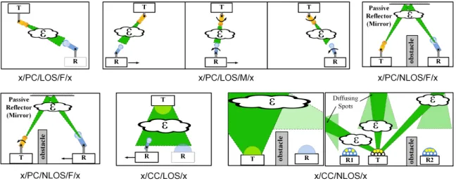
2.7 Different FSO link configurations in the proposed classification. The link configurations are consistent across different environments, and therefore we use the cloud symbol to represent the environment (). . 39
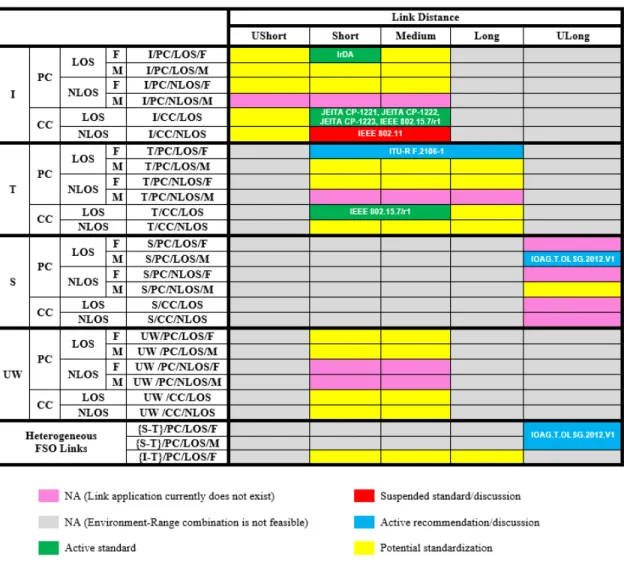
2.8 Classification of existing FSO standards and recommendations using the proposed FSO classification scheme. . . 40
2.9 T-SE (a) R-State. (b) T-State. (c) S-State. . . 45
2.10 Difference between heterogenous FSO links and heterogenous FSO sys-tems. . . 86
3.1 Electromagnetic Spectrum. . . 99
3.2 Classification of conventional wired DCNs. . . 109
3.3 Proposed data center network (DCN) classification. . . 110
3.4 Intra and inter-rack communications in 60 GHz wireless DCs as envi-sioned by Ramachandran et al. [4]. . . 115
3.5 Design by Vardhan et al. [5]. . . 117
3.6 Rack and server design in Cayley DCN [6]. . . 118
3.7 Cayley DC [6] (a) Intra-rack topology. (b) Inter-rack topology. (c) Diagonal XYZ routing. . . 120
3.8 Design proposed by Suto et al. [7] . . . 125
3.9 Design proposed by Riza et al. [8] . . . 128
3.10 FireFly by Hamedazimi et al. [9] . . . 129
3.11 T-SE (a) R-State. (b) T-State. (c) S-State. . . 132
3.14 Design proposed by Joseph et al. [12] (a) Intra-rack. (b) Inter-rack top
(top) and side (bottom) views. . . 136
4.1 (a) Proposed Design of an OWC-DC. (b) Proposed Fully Connected,
Switch-Free OWC Rack of Servers. . . 148
4.2 A Fully Connected OWC Rack of Servers. . . 155
4.3 Received power by Servers. . . 158
4.4 Eye Diagrams of OWC (top) and Fiber Optics (bottom) at 2.5 Gbps
and PT = 10 mW (a) s=1. (b) s=25. (c) s=39. . . 159
4.5 Eye Diagrams at different servers (S = 1, 25, and 39) using 2.5 Gbps
and varying transmitted power (PT). . . 160
4.6 OWC-DC Cost Function Compared to CDCs. . . 163
5.1 Examples of multiprocessor and NoC network topologies using
poly-gons (a) Square. (b) Hexagonal. . . 166
5.2 Examples of the proposed polygonal OWCell DCN (a) Topology (b)
C(n,1, S), forn = 4, 6, and 8. . . 168
5.3 Examples of the proposed OWCell DCN topologies,C(n,2, S): (a)n =
4, and 8 (b)n = 6. . . 169
5.4 Different partitioning in CGM6
1 (top) and CGM18 (bottom). Bold
edges form the corresponding cut-set. (a) n−1 (b) 2(n−2) (c) (n2)2 170
5.5 Bisection width (solid) and diameter (dashed) in C(8, t, S) for even t.
The graph is stretched around the column of shared ToRs to illustrate
the bisection width. . . 172
5.6 Bisection width (solid) and diameter (dashed) in C(8, t, S) for odd t.
The graph is stretched around the shared column of CoRs to illustrate
the bisection width. . . 173
5.7 Bisection width (solid) and diameter (dashed) in C(6, t, S). (a) t = 2
(b) t= 3 (c) General case. . . 174
5.8 ToR OWC transceiver design. . . 177
5.9 Types of nodes inC(4, t, S) OWCell DCN. Type 1 nodes
(even-column/odd-row indices) and Type 2 nodes (odd-column/even-(even-column/odd-row). . . 179
5.10 ToR OWC complete transceiver design. . . 182
5.11 Aggregated throughput of C(4, t, S) for different OWCell DCN sizes
and different servers per rack S = 15 (most left), 20, 25, 30, 35, and
40 (most right). . . 185
5.12 Performance of C(4,40, S) for different DCN Sizes. . . 186
5.13 Performance of Hybrid Switching vs. OCS in a 16k server OWCell
DCN C(4,14,40). . . 187
5.14 Comparison of throughput and number of inter-rack links (log scale)
of OWCell vs. HyScale DCN. . . 188
6.1 N ×N SaD switch [13]. . . 197
figurable. . . 197
6.3 N ×N SUM-SaD switch [14]. . . 198
6.4 N ×N MEMS switch with one-port bridging capability [15]. . . 199
6.5 T-SE (a)R-State. (b)T-State. (c) S-State. . . 199
6.6 Switching modes in a proposed 2×2 switch. . . 200
6.7 Multicast in 6×6 crossbar using T-SEs. . . 201
6.8 Possible permutations using the proposed 3×3 switch. . . 202
6.9 An N ×N switch with an (N −1)×(N −1) subswitch used in the induction step. . . 204
6.10 Hardware complexity for an 8×8 switch. . . 211
6.11 Splitting power penalty in an 8×8 switch (a) Minimum. (b) Average. (c) Maximum. . . 213
6.12 Comparative cost analysis for the proposed switch. The curves repre-sent the relative cost effectiveness of the proposed switch as compared to the existing SaD switches with respect to SEs. Shaded regions are invalid design regions. White region above (below) a curve indicates that the proposed switch is more (less) cost effective compared to the corresponding SaD switch for specific number of ports N. . . 218
7.1 Multicast in 6×6 proposed switch using T-SEs. . . 221
7.2 This figure illustrates the process of configuring an 8 ×8 proposed switch with three unicast and two multicast requests using Algorithm 1. Black lines indicates the T-SEs that will be eliminated at the end of current iteration. Each subfigure shows the accumulative result of a request being routed. (a) Unicast requesth4,5i. (b) Unicast request h5,1i. (c) Unicast request h6,7i. (d) Multicast request h2,{2,6}i. (e) Multicast request h8,{3,4,8}i. (f) Fully configured switch with all requests. . . 224
7.3 M ×M rectangular sub-switch. . . 226
7.4 General structure of an N ×N triangular switch. . . 228
7.5 Two 6×6 RNB switches on a single square substrate. . . 236
7.6 Hardware complexity for 8×8 switches. . . 238
7.7 Splitting power penalty in an 8×8 switch [16] withα=ζ = 43%, and η=β = 87% (a) Minimum. (b) Average. (c) Maximum. . . 240
7.8 Splitting power penalty in an 8×8 switch with α = 10%, ζ = 90%, and η=β = 99% (a) Minimum. (b) Average. (c) Maximum. . . 245
7.9 Comparative cost analysis for the proposed switch. The curves repre-sent the relative cost effectiveness of the proposed switch as compared to the existing SaD switches with respect to SEs. Shaded regions are invalid design regions. White region above (below) a curve indicates that the proposed switch is more (less) cost effective compared to the corresponding SaD switch for specific number of ports N. . . 247
List of Tables
2.1 Summary of OWC/FSO Link Classifications in Literature. . . 31
2.2 Proposed classification framework and notation of FSO communication link configurations. Grayed cells indicate infeasible link environment-range combinations. We use No Application (NA) to indicate that an application for the specific environment-range combination has not been reported in the literature yet. . . 37
2.3 Indoor FSO Link Impairments. . . 51
2.4 Summary of IrDA Standards. . . 53
2.5 Terrestrial FSO Link Impairments. . . 64
2.6 Space FSO Link Impairments. . . 70
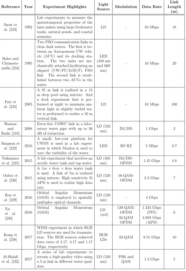
2.7 Summary of Major UW/PC/LOS/F/x UOWC Link Experiments. . . 77
2.8 UOWC Link Impairments. . . 78
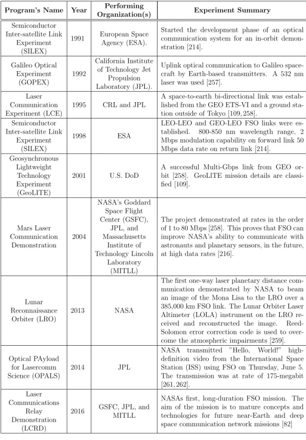
2.9 Summary of Major Space and Heterogenous (Ground-Space) FSO Link Experiments. . . 85
2.10 Classification of Heterogenous and Hybrid FSO Systems Using the Pro-posed Framework. . . 88
3.1 Comparison Between 60 GHz RF and FSO Wireless Technologies for DC Application. . . 102
4.1 Summary of the OWC Link Performance Compared to the Optical Fiber Link. . . 161
4.2 Cost of Different Components used in CDC . . . 162
4.3 Total Cost of Different CDC Configurations . . . 162
5.1 Properties of Complete Graph Meshes,C(n, t, S). . . 169
5.2 Selection of routing output port in C(4, t, S). . . 180
5.3 Number of Inter-Rack Links and Average Hop Count in OWCell and HyScale. . . 191
6.1 Summary of Hardware Complexity of Different Architectures Φ = 2(dlog2(N)e+1)−2. . . . . 210
Φ = 2 2 −2 . . . 237
Chapter 1
Introduction
Big Data is a term used to describe high volume, high velocity, and/or high variety data sets [17]. Big Data applications can be found in disciplines like, Internet-of-Things (IoT) [18], Bioinformatics [19], Social media [20], and Nanoinformatics [21]. For example, it is expected that the Large Synoptic Survey Telescope (LSST), which will be deployed in Chile in 2016, will acquire around 10 Gbps for ten years resulting in a final disk storage and database size of 400 Exabytes and 15 Petabytes, respectively [22]. According to the International Data Corporation (IDC), the IoT market is expected to grow from 9.1 billion devices and objects connected to the Internet in 2013 to 28.1 billion by 2020 [23]. As the portfolio of bandwidth and computation intensive Big Data applications continues to grow, so does the demand for efficient
Data Centers (DCs) that support 100,000 servers and beyond [24].
A DC Network (DCN) is the networking infrastructure that provides the
intra-and inter-DC networking services. It is, therefore, essential to design an efficient high-speed/high-bandwidth DCN to meet the high computing and communication demands in DC. The design of a DCN must also satisfy several requirements such as scalability, low latency, availability, and cost effectiveness. Other practical
con-cerns, including cabling complexity, power consumption, and cooling, must also be considered in the design [9, 25].
The design space of DCNs is witnessing an accelerated evolution vis-`a-vis academia
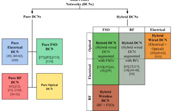
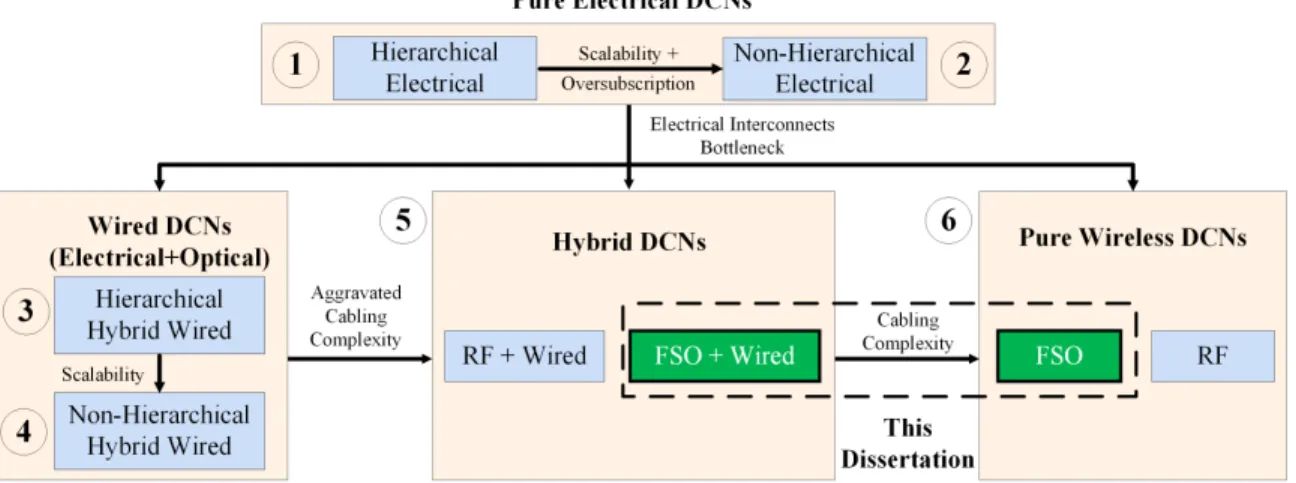
and industry are advancing new technologies for DCNs as the portfolio of bandwidth and computation-intensive Big Data applications continues to expand. Thus, the de-sign and development of highly efficient high-speed/high-bandwidth DCNs is critical to maximize total aggregated computing and communication capacities of future DCs. For the rest of this chapter, we use Figure 1.1 to pictorially depict our understanding of how the design space of DCNs is reshaping. Each box in Figure 1.1 represents a design philosophy. Links between boxes represent the challenges faced by each design and the arrow points to the proposed solution.
Figure 1.1: DCN design space roadmap.
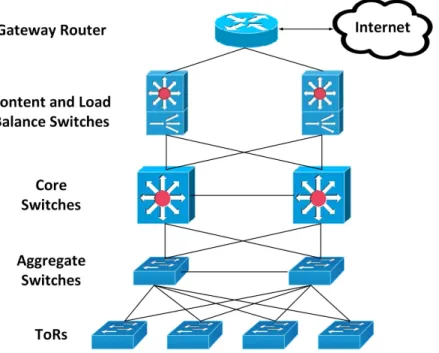
In a widely used conventional hierarchical tree-based DCN architecture, servers
are stacked in racks that are arranged in rows. A Top-of-Rack (ToR) switch is used to perform intra- and inter-rack communications [see Figure 1.2]. A gateway router is used to connect the front end of the content and load balancing switches with the internet. At the back end, the content and load balancing switches are connected to servers using two (core-ToR) or three (core-aggregate-ToR) layers of switches.
Electrical cables are mostly used for intra- and inter-rack communication links [Box 1 in Fig. 1.1]. As we move up in the tree, more powerful links and switches must be used with over-subscription factors of 1:2 or more at higher levels in the tree. High oversubscription ratios, however, adversely impact inter-rack communications [26].
Figure 1.2: Conventional hierarchical tree-based DCN architecture.
Analysis of real world DC traffic statistics shows that some applications do have unpredictable traffic patterns and unbalanced traffic distributions [27–32] that can
lead to temporaryhotspots. It is difficult for hierarchical DCN architectures to
sup-port or adapt to unpredictable changes in traffic patterns. Therefor, the performance of the network may degrade due to inadequate network capacity and flow conges-tions [31, 32]. Current trends in high-speed/high-bandwidth DC applicaconges-tions show that the hotspot problem is likely to worsen in the future [6, 33, 34]. Moreover, hi-erarchical DCN architecture may have low scalability and performance [35–39], and may also require expensive switches for supporting large number of servers [29].
re-searchers improved existing hierarchical topologies (e.g., Fat-Tree [40], VL2 [41], and PortLand [42]), and developed new non-hierarchical, mostly recursive, topologies (e.g., BCube [35], DCell [36], FiConn [39], DPillar [37], and BCN [38]). In
non-hierarchical DCNs [Box 2 in Fig. 1.1], large number of links and switches with
variants of multipath routing are used such that the core of the network is not over-subscribed [27]. At any point in the network, full bisection bandwidth is available to forward all incoming traffic. Non-hierarchical DCN architectures demonstrate better scalability and fault tolerance attributes as compared to the conventional hierarchi-cal architectures [27], however, the performance improvement is achieved at the cost
of larger number of wires leading to increased cabling complexity problems (e.g.,
cable management, maintenance, and heat dissipation).
Electrical interconnects used by most existing DCNs (hierarchical/non-hierarchical are increasingly becoming a bottleneck as optical-electrical-optical (O-E-O) conver-sion is required at every port. Moreover, recent real world DC traffic traces show that more than 95% of the data are being transferred by the top 10% largest flows. Thus, interconnects that can support elephant flows (i.e., flows with large amount of data) may be more favorable than guaranteeing full bisection bandwidth between large number of pairs of servers across the DCN. This in turn has motivated researchers to investigate the use of optical interconnects in DCNs [18, 19, 21-28], especially for transferring the elephant flows.
Another approach to tackle the hotspot problem is to realize a “flexible” network to establish on-demand links between nodes that are susceptible to the hotspot prob-lem. The on-demand links can be based on a wired [Box 3 and 4 in Fig. 1.1] or a wireless [Box 5 in Fig. 1.1] technology. In case of wired technologies, commodity switches are deployed to connect a subset of nodes and provide on-demand wired links when needed. The advantage of the wired solution is that the flexible wired
network realized is consistent with the original DCN especially that most DCNs de-ployed today can be classified as wired DCNs that use copper-cables and fiber optics for communication. For the wired flexible network to operate efficiently, the network must interconnect the nodes that are susceptible to the hotspot problem. However, prediction of such nodes is a difficult problem. Thus, a wired solution may not be able to provide the required flexibility. Moreover, a wired flexible network requires the deployment of a larger number of cables escalating problems related to cabling complexity.
The potential capability of establishing flexible on-demand wireless links have motivated the researchers to investigate wireless communication as a possible solution for hotspot and cabling-complexity problems, simultaneously. A wireless technology can be used either to augment a wired DCN; leading to hybrid DCN [Box 5 in Fig. 1.1] or to develop a pure wireless DCN [Box 6 in Fig. 1.1]. There are two candidate wireless technologies, radio frequency (RF) and optical wireless communication (OWC), also known as free space optics (FSO). The difference between the two terms will be explained in detail in Chapter 2. For the sake of brevity, we use the terms OWC and FSO interchangeably in this dissertation. In case of RF, researchers focus on 60 GHz RF technology since it stands out from other RF technologies due to its short range and high bandwidth. In FSO communication, a modulated light beam propagates in free space with no fibers involved. Therefore, FSO combines the flexibility of wireless communication and the high-speed/high-bandwidth of the optical communication.
Ramachandran et al. propagated the idea of using 60 GHz RF technology in DCN design [4]. Following their work, considerable research has been devoted to investigating the feasibility of deploying 60 GHz RF technology in DCNs [6, 43–49]. Although promising, 60 GHz technology has its limitations as it has lower practical bandwidth, and suffers from high attenuation and propagation loss [4,9,50]. Radiation
Figure 1.3: DCN design space.
patterns of 60 GHz impose additional restrictions on the activity of wireless modules in close proximity because of interference. This increases the complexity of routing and network management, and reduces the throughput [6].
Recent advances in FSO/OWC technology have narrowed the gap between FSO and RF technologies to the point that FSO is now seen as a complement technology for RF in next-generation communication systems, such as 5G wireless networks. RF technology can offer high data rates when high carrier frequencies are used, however, RF propagation becomes more LOS dependent. Thus, key features of RF technolo-gies, such as, mobility, coverage, and receiver sensitivity, become unclear [51]. Both 60 GHz and FSO technologies are comparable as they operate in an unregulated, yet
standardized band of the spectrum. Moreover, both technologies have short range and potentially low cost making them strong candidates for networking in DCNs. In case of FSO, the very high carrier frequency and the relatively large detector area provide spatial diversity that averts multipath fading. On the other hand, RF links experience signal magnitude and phase fluctuations. Therefore, the design of FSO links can be simpler than that of RF [1].
The advantages of FSO technology and its successful deployment in a wide range of applications has motivated researchers to investigate the use of FSO in the design of DCNs [9, 11, 50, 52]. Examples of applications in which FSO has already found its place are, mobile networks backhaul, space communications, and underwater sensing. The notable increasing use of FSO technology in different applications is due to the advantages presented by FSO technology, such as, high data rate, low interference, and high speed of light that is approximately 1.5 times faster than that of fiber optics, which mean less latency.
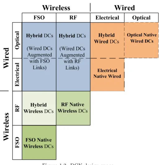
Figure 1.1 is an evident that DCN design space is reshaping and there is a current need to rethink the design philosophy of DCNs [52, 53]. There are four technologies that can be used for communication in DCNs, wired electrical cables, wired optical fiber, wireless RF technology, and wireless FSO technology. Figure 1.3 depicts the resulting DCN design space. Each of these four technologies can be used individually, leading to a pure (electrical/optical/RF/FSO) DCN. On the other hand, different technologies can be integrated leading to wired (electrical + optical), wireless (FSO + RF), or a hybrid DCN; (FSO + wired) or (RF + wired).
Since the deployment of 60 GHz and FSO technologies in DCNs has not yet been
fully investigated, we focus our research on pure FSO, and hybrid (FSO + wired)
DCN designs. It is not yet known which of these two types of DCNs provides a better
DCNs. To this end, we propose OWCells, a class of optical wireless cellular data center network architectures in which fixed line of sight (LOS) optical wireless
com-munication (OWC) links are used to connect the racks arranged inregular polygonal
topologies. We present the OWCell DCN architecture, develop its theoretical
under-pinnings, and investigate routing protocols and OWC transceiver design. To realize a fully wireless DCN, servers in racks must also be connected using OWC links. There is, however, a difficulty of connecting multiple adjacent network components, such as servers in a rack, using point-to-point LOS links. To overcome this problem, we pro-pose and validate the feasibility of an FSO-Bus to connect multiple adjacent network components using NLOS point-to-point OWC links.
In DCNs, a rack requires a combination of local (intra-rack) and remote (inter-rack) data access to complete a task. Therefore, applications hosted by DCNs gener-ate large demands for bandwidth with different communication patterns involving a combination of unicast, multicast, in-cast, and all-to-all-cast traffics [24, 54].
For example, Hadoop is one of the widely used implementations of MapReduce [55], which is a distributed processing framework for large datasets. Distributed sys-tems use data replication to offer scalability and availability of data. For example, a file written to Hadoop Distributed File System (HDFS) is split into smaller data blocks that have configurable size. To ensure availability and scalability, Hadoop randomly distributes three replicas of each data block among distinct nodes housed in different servers, in the network [56], two of which are on the same rack to reduce inter-rack communication. Therefore, Hadoop requires in-cast traffic delivery during the shuffle stage of MapReduce, and requires multicast for data replication, parallel database join operation, as well as data dissemination in virtual machine (VM) provi-sioning [54]. As part of the design of the OWC transceiver, we develop a new class of strictly and rearrangeably non-blocking multicast optical switches in which multicast
is performed efficiently at the physical optical (lower) layer rather than upper layers (e.g., application layer).
The main contributions of this dissertation are as following.
1. We present a multi-level classification for FSO technology applications in four
different communication environments, namely: indoor,atmospheric,space, and
underwater. To the best of our knowledge, there exists no classification/survey that addresses the variety of the FSO technology applications in all four envi-ronments.
2. We propose a classification that can be used to classify existing and emerging wired and wireless DCNs. The proposed classification leads to a nearly com-plete picture of the design space for DCNs. This help us to identify potential unexplored solutions for next-generation DCNs.
3. We present, OWC-Bus, a communication scheme used to connect multiple
ad-jacent network components using OWC links..
4. We develop, OWCells, a family of cellular optical wireless DCN architectures. OWCells utilize line-of-sight (LOS) OWC links to connect racks that are ar-ranged in regular polygonal shapes.
5. We propose a new class of strictly blocking (SNB) and rearrangeably
non-blocking (RNB) FSO multicast switches that utilizes tri-state switching
ele-ments (T-SEs) and is optimal with respect to hardware complexity.
1.1
Dissertation Outline
In Chapter 2, we present a classification scheme for FSO technology and use the classification to review both; the research and standardization literature of the FSO technology. In Chapter 3, we propose a classification that can be used to classify any DC, including existing wired and emerging wireless DCs. We use the classification to review and highlight the challenges faced by DCNs in the literature which motivates to our work. In Chapter 4, we present an OWC-DC that is based on OWC-Bus.
Although the design proposed in Chapter 4 present a useful design for OWC rack of servers, the conventional row-based DCN arrangement forms a great impairment for wireless connectivity in DCNs. We dedicate Chapter 5 to discuss the proposed cellular optical wireless DCN architectures, OWCells, that can overcome the problems encountered by conventional row-based DCNs.
In Chapters 6 and Chapter 7, we propose a new class of strictly non-blocking (SNB) and rearrangeable non-blocking (RNB) FSO multicast switches using tri-state switching elements (T-SEs).
Chapter 2
Optical Wireless Communication
(OWC) Technology
Free Space Optical (FSO)communication technology, also known as Optical Wireless
Communications (OWC), has regained a great interest over the last few years. In
some cases, FSO is seen as an alternative to existing technologies, such as radio fre-quency. In other cases, FSO is considered as a strong candidate to complement and integrate with next-generation technologies, such as 5G wireless networks. Accord-ingly, FSO technology is being widely deployed in various indoor (e.g., data centers), terrestrial (e.g., mobile networks), space (e.g., inter-satellite and deep space com-munication), and underwater systems (e.g., underwater sensing). As the application portfolio of FSO technology grows, so does the need for a clear classification for FSO link configurations. Most existing surveys and classifications are single-level classifi-cations, and thus not inclusive enough to accommodate recent and emerging changes and developments of different FSO link configurations and systems. In this chapter, we propose a multi-level classification framework to classify existing and future in-door, terrestrial, space, underwater, and heterogenous FSO links and systems using
common and simple unified notation. We use the proposed classification to review and summarize major experimental work and systems in the area until 2017. Using the proposed classification and survey, we aim to give researchers a jump-start to tap into the growing and expanding realm of the FSO technology in different environ-ments. The proposed classification can also help organize and systematically present the progress in the research on FSO technology. This makes the identification of the market needs for standards an easier task. Moreover, different entities involved in the standardization process including academic, industry, and regulatory organiza-tions can use the proposed classification as a unified language to communicate during the early stages of standard development which require ambiguity-free discussions and exchange of ideas between different standardization entities. We use the pro-posed classification to review existing standards and recommendations in the field of FSO. It is also envisioned that the proposed classification can be used as a unified framework to define different FSO channel models for simulation tools.
2.1
Introduction
Emerging Big Data applications and systems found in disciplines like social media and Internet-of-Things (IoT), are characterized by being bandwidth-intensive and performance-sensitive. The IoT market is expected to grow from 9.1 billion devices and objects connected to the Internet in 2013 to 28.1 billion by 2020 [23], that is more than three times the global population expected by 2020. As such applications and systems rapidly move closer to end users, wireless communication systems, are the favored communication technologies as they allow for user mobility. Moreover, wireless technologies avoid most of the inherent complexity that wired technologies suffer from, such as, long setup time, right of the way for digging, and the sunk cost
once the cables are laid [57]. It is expected that two-thirds of total IP traffic by 2020 will be generated by wireless and mobile devices [58].
Figure 2.1: Part of the electromagnetic (EM) spectrum showing the frequency (and wavelength) ranges for each band.
Figure 2.1 depicts part of the electromagnetic (EM) spectrum and the frequency (and wavelength) ranges for each band of the spectrum. As the frequency increases, the wavelength and effective area of an antenna decrease. The carrier frequency is selected based on the application. For example, ground-to-submarine communications utilize audio waves due to its very long wavelengths (i.e., very low frequency and very large antenna) and the limited propagation capability of RF signals in electrical conductors such as salt water due to absorption. On the other hand, radio frequencies in the Ultra High Frequency (UHF) and Super High Frequency (SHF) band range are capable of penetrating windows, walls, and ceils. Therefore, the IEEE 802.11b/g/n (WiFi) networks utilize the unlicensed 2.4 GHz UHF and 5 GHz SHF radio bands.
RF is a mature technology and is being widely deployed in many indoor, terres-trial, and space communication systems. However, the propagation nature of the RF communication systems raises a problem of interference, which in turn affects the usability of frequencies, and hence, the capacity. Therefore, the RF spectrum is regulated by the local and international authorities to limit the interference, and guarantee proper operation and coexistence of systems relying on RF. As the
appli-cations of RF communication are progressively increasing, the RF spectrum becomes more congested, scarce and thus expensive to acquire. Several efforts are put from research and industry to stretch the capability of existing wireless technologies (e.g., alleviating interference) and to develop new ones to fulfill the emerging needs [59, 60].
Free Space Optical (FSO)communication, also known asOptical Wireless
Commu-nication (OWC) as discussed later in Section 2.2.1, is being extensively investigated over the last few decades as an attractive alternative technology to RF. Similar to fiber optics, data are used to modulate a light beam in FSO. The light beam then propagates from one point to another, however, in a wireless manner. The recent spike in interest in FSO technology stems from the fact that FSO combines high-bandwidth of optical communication systems and the flexibility of wireless technologies.
FSO technology operates in a broad spectrum (see Figure 2.1) including Near Infrared (NIR), Visible Light (VL), and Ultraviolet (UV) bands. Conventionally, terrestrial and space FSO links operate in the NIR band similar to fibre-optic
sys-tems [61]. As will be shown in subsequent sections, terrestrial systems can also
operate in the VL [62] and UV [63] bands. On the other hand, Indoor FSO links commonly operate in the NIR [64] and VL [65] bands, whereas, underwater OWC systems operate in the NIR [66] and VL [67] bands. The extremely short wavelengths (i.e., high frequencies) at which FSO systems operate make FSO detectors immune to multipath fading (i.e., large fluctuations in received signal magnitude and phase) as opposed to RF links, which are highly susceptible to multipath fading. This can be attributed to the spatial diversity resulting from the fact that FSO detector areas are extremely large compared to the wavelengths [1]. In addition to the unregulated spectrum, most of the optical components used in FSO links are cheaper, smaller, lighter and have lower power consumption as compared to that of RF components leading to cost and energy saving [3, 68–71]. Although most of the FSO components
are cheaper, lighter, and smaller than that of RF links, one must keep in mind that FSO networking solutions are not as mature and commercially available as their RF counterpart. We believe that this is a main contributor to the fact that FSO com-mercial solutions can be sometimes more expensive and bulkier especially in the case of terrestrial FSO links [72]. As the technology becomes more popular and with the expected increase in the market competition, the price of FSO solutions is expected to drop. On the other hand, as the technology matures, designer of FSO solutions will be able to develop the best design practices which will influence the size of the modules used in the FSO systems.
FSO technology has also been considered as a complementary technology to ex-isting RF systems since FSO and RFs do not interfere [2]. This property is very important for applications in which interference with RF systems must be avoided such as in hospitals and in personal entertainment systems on commercial aircrafts to mitigate the interference with the RF-sensitive navigation and avionics electronic systems [73]. Moreover, the next generations of wireless communication systems (e.g., 5G) incorporate several complementary access technologies along with the RF tech-nology, including FSO [74, 75].
A preliminary optical communication experiment was among the secondary ob-jectives of the mission Gemini 7 conducted by NASA in 1965 [76]. The experiment was only partially completed due to the cloud obscuration and the spacecraft alti-tude restrictions [77]. Three years later, Erhard Kube published the original FSO
communications white paper ”Information transmission by light beams through the
atmosphere” [78]. In this chapter, E. Kube explained the possibility of transmitting
data through the atmosphere using green (0.6 µm) and red (0.8 µm) laser sources.
Continued development of lasers led to the development of a small and continuous-beam semiconductor light sources that work at room temperature by Zhores Alferov
in 1970. This invention opened new horizons for the development of OWC systems. In 1979, Gfeller and Bapst introduced the first indoor OWC system in which the dif-fuse emissions in the infrared (IR) band were used [79]. The continued research and development by academic institutions, industry and military organizations, enabled the FSO communication to find its place in many applications, such as, mobile net-works backhaul [80, 81], space communication [82], underwater (UW) sensing [83, 84], wireless sensor networks (WSNs) [63], indoor local area networks [85, 86], data center networks (DCNs) [64] and many other applications.
2.1.1
Motivation and Contribution
Advantages of the FSO technology have been known for a long time. However, utiliza-tion of these advantages was facilitated by recent development and advances in FSO enabling technologies. As a result, a large number of research papers on new FSO applications has been published recently. Given that most of the FSO technology classification efforts were made in the late 90s, we believe that existing classifications of FSO technologies are outdated [1, 2, 87].
Most of the old classification efforts simply review and differentiate FSO systems without taking into consideration development of new/future FSO links. Therefore, it may be difficult, if not impossible, to fit some of the emerging and future configuration
classes into existing single-level classification schemes. Accordingly, many survey
papers have to introduce additional classes, which makes the overall classification scheme inconsistent and nonsystematic in its expansion. For an example, consider the quasi (multi-spot) diffuse system [88, 89] propagated as a sperate class despite its similarities to diffuse systems [1, 73, 90, 91]. Furthermore, a large number of new developments in FSO result in several inconsistencies, and sometimes, contradictions between various classifications and definitions such as in their naming conventions
or operational principles. For example, the three notations LOS/Directed, LOS, and Point-to-Point all refer to the same FSO link configuration [1, 2, 73, 87, 90–95].
We believe that there is a need for a classification that can express the existing, emerging, and future FSO link configurations and applications in a systematic way. Accordingly, in this chapter, we have the following three major objectives.
• Develop a rigorous multi-level classification based on a set of notation that can
be systematically used to express various present and emerging FSO link con-figurations to help reduce ambiguity. To show the effectiveness of the proposed classification, we use it to classify different link configurations listed in vari-ous existing classifications. We also use the proposed classification to classify FSO link configurations that could not be classified before. Furthermore, we show how the proposed classification can evolve to include any future FSO link configurations.
• Survey FSO technology applications in different communication environments,
namely: indoor,atmospheric, space,underwater, andheterogenous. To the best
of our knowledge, there exists no classification/survey that addresses the variety of the FSO technology applications in all environments. For each environment type, we summarize recent research efforts and provide a list of selected refer-ences for applications on each link configuration. We also discuss the typical impairments encountered by each link configuration and possible solutions for these impairments. Finally, we classify and review existing standards and rec-ommendations for FSO technology in each environment.
• Put the proposed classification into action and use it to describe different
exist-ing FSO systems. We reviewheterogenous FSO systems in which different types
FSO systems in which FSO is combined with a different technology (e.g., RF). In addition to classifying FSO systems, we envision that the unified framework presented here can also be used to develop modular and consistent FSO channel models for FSO simulation tools.
It should be noted that the development of FSO in each of the four environments (or a subfield thereof) represents a broad research area in its own right. Thus developing a single comprehensive survey to cover all the developments, impairments, and solutions in detail is infeasible. That being said, in this chapter, we aim to give researchers a jump-start to tap into the growing and expanding realm of the FSO technology in different environments. To this end, we present a novel classification scheme for FSO links. To demonstrate the effectiveness of the proposed classification, we bring recent advances in all fields of FSO in a single place saving researchers the time and effort to capture the big picture. Therefore, our contribution is a comprehensive breadth-focused survey and we acknowledge that, breadth-focused and dedicated survey papers based on our proposed classification may be needed to cover a particular domain in detail in the future.
2.1.2
Chapter Organization
The remainder of this chapter is organized as follows. In Section 2.2, we discuss the generic FSO link components, including light sources, photodetectors, and modula-tion schemes. We dedicate Secmodula-tion 2.3 to discuss related work. In Secmodula-tion 2.4, the
proposed classification of FSO link configurations is presented and various schemes
are explained. Sections 2.5 - 2.9 demonstrate the use of the proposed classification scheme to classify FSO applications and related standards/recommendations in in-door, terrestrial, space, underwater, and heterogenous environments, respectively. We then use the proposed classification to review different FSO systems in Section 2.10.
Research directions and open problems for FSO systems are discussed in Section 8.1.1. Summary is given in Section 2.11.
2.2
Preliminaries and Basic Concepts
In this section, we discuss preliminaries and basic concepts related to optical wireless communication. We discuss the naming convention of the optical wireless technology since it has been observed that researchers use different names to refer to the optical wireless technology in the literature. We also briefly discuss the preliminaries and basic components of a generic FSO link, such as light sources, photodetectors, and modulation schemes. The details of the components used in optical communication systems and the advances in the research related to these components are, however, beyond the scope of this chapter. Interested readers can refer to the papers and books discussing the theory of operation, variations and advancement of different types of
light sources and photodetectors [96–104]. Discussion on eye safety and existing
regulations can be found in [105–108]. Moreover, excellent summaries and taxonomy of modulation schemes in OWC are available in [51, 81, 90].
2.2.1
Naming Convention - FSO vis-`
a-vis OWC
Optical wireless and fiber-optic communication systems operate in the same band of the spectrum and have similar transmission bandwidth capabilities, therefore, optical
wireless communication is used to be referred to as fiber-less optics. As the
fiber-less optics technology continued to advance and used in new domains, new names
for the technology emerged in the literature, such as; Lasercom, Optical Wireless
Communication (OWC), and Free Space Optics (FSO). Over the last few decades,
“lasercom” are considered archaic [109].
It has been noticed that the term OWC is used in the literature to refer to indoor and outdoor fiber-less optical systems, whereas, the term FSO is mostly used to refer to outdoor fiber-less optical systems. In a recent classification and survey [3], Kaushal and Kaddoum use the notation OWC to refer to the fiber-less optics technology. The authors then classify OWC technology into Indoor Systems and Outdoor Systems (FSO). The FSO system is further classified into Terrestrial Links and Space Links. The use of FSO to refer to outdoor links is because the technology utilizes an unguided channel in both the terrestrial atmosphere and the vacuum (outer space). However, this is also true for indoor and underwater environments where the fiber-less optical systems are utilizing unguided channels. This led many researchers to refer to the fiber-less optical systems using the notation FSO in indoor [71, 110] and underwater [111–113] environments.
Since FSO and OWC refer to the fiber-less communication with unconfined medium disregard the environment in which the link is established, and taking into consider-ation the fact that both terms have been widely used in the literature, we use both
terms interchangeably in this chapter to refer to the fiber-less technology in any
en-vironment. It is found that the OWC in the underwater (UW) environment is widely
referred to as Underwater Optical Wireless Communication (UOWC). Therefore, for research related to UW OWC, we use the term UOWC to maintain the consistency with the literature.
2.2.2
Light Sources
The most commonly used light sources in FSO systems are Laser Diodes (LDs) and
Light Emitting Diodes (LEDs). LDs are preferred in applications with high data
bandwidths. There are, however, standards and power restrictions controlling the usage of the LDs to mitigate potential eye and skin safety hazard [51].
LEDs, on the other hand, are preferred in low/medium data rate indoor appli-cations. This is because LEDs are cheaper than LDs and more reliable. Moreover, LEDs are extended sources with large-area emitters. Therefore, LEDs can be oper-ated safely even at relatively high powers. Compared to LDs, LEDs support lower data rates [93, 114]. However, data rates up to 1 Gpbs using LEDs and rate-adaptive discrete multitone modulation are achieved [115]. In [116], Tsonev et al. present a 3
Gbps FSO link operating in the visible light band using a single 50-µm gallium nitride
LED and Orthogonal frequency division multiplexing (OFDM) modulation scheme.
2.2.3
Photodetectors
Positive-Intrinsic-Negative (PIN) photodetectors and Avalanche Photodetectors (APDs) are the most commonly used types of photodetectors in FSO systems [1, 51]. PIN photodetectors are preferred in low cost and low data rates FSO links. This is because they are cheap, can operate at low-bias, and have tolerance to wide temperature fluc-tuations [1, 93]. APDs are PIN photodetectors operating at very high reverse bias. This leads to high internal electrical gain that increases the SNR at the receiver [1,2]. Compared to PIN photodetectors, APDs have superior performance especially in sys-tems with limited ambient light noise. Therefore, APDs are favored in high data rates and high-performance FSO systems. On the other hand, APDs are more expensive and their gain is temperature-dependent. Analysis of different noise sources related to PINs and APDs are discussed in [51].
Recent advances in the field of graphene, two-dimensional materials, and nano-materials, such as plasmonic nanoparticles, semiconductors, quantum dots have paved the way to the development of ultrafast photodetectors that work over a broad range
of wavelengths [117–119]. These photodetectors facilitate ultrahigh bandwidth optical communication systems supporting higher data rates.
2.2.4
Modulation
Different modulation schemes have different transmission reliability, energy, and spec-tral efficiencies. A modulation scheme is selected based on the type of the application. For example, the simplicity of On-Off keying (OOK) modulation makes it the most commonly used modulation scheme in FSO systems. However, OOK can be inefficient in more complex systems that require high data rate such as deep space communica-tion. For such applications, Pulse Position Modulation (PPM) or one of its variations, e.g., Variable-PPM (VPM), is usually preferred [51, 84, 120].
Both OOK and PPM are considered as single-carrier pulsed modulation. As the data rate increases, single-carrier modulation schemes become inefficient due to the increase ISI [121]. Moreover, PPM requires complex time-domain equalization which can be problematic for FSO links with severe channel conditions and impairments [90]. In this case, Subcarrier Intensity Modulation (MSIM) and Multiple SIM (MSIM) such as Orthogonal Frequency-Division Multiplexing (OFDM) are used. In SIM-based approaches, an optical source is driven by a pre-modulated RF signal carrying the data. A DC bias is added to the signal before it is used to drive the optical source to maintain an all positive amplitude because the input of the LD must be non-negative [122]. Compared to single-carrier modulation schemes, SIM techniques help mitigate channel impairments and provide a simpler and cost-effective implementation [123]. Moreover, SIM improves bandwidth efficiency as compared to that of PPM techniques [124].
The addition of the DC bias (non-information signal) to the pre-modulated RF signal to avoid non-negative amplitudes leads to poor power efficiency. As the number
of carriers increase, such as in MSIM techniques, the DC bias required may become very large to prevent clipping and nonlinear distortion in the optical domain. This, in turn, leads to high peak-to-average power ratio (PAPR) and worsens the power efficiency [124]. The nonlinearity of light source is another challenge in MSIM tech-niques [122, 125]. The nonlinearity at the light source leads to interference among the subcarriers and broadening of the signal spectrum resulting in mixed signals and Inter-Modulation Distortion (IMD). To limit the transmit power and reduce the IMD, MSIM techniques need to employ small number of carriers. However, this limits the transmission data rate. Another approach to eliminate the IMD is to transmit each subcarrier using a separate optical source [126].
To improve the performance of the MSIM techniques, a PAPR reduction technique can be used to make the signal less vulnerable to the nonlinear distortion [127]. Another approach is to have the nonlinearities compensated for by predistortion or postdistortion [128, 129]. In [124], Hassan et al. present a detailed survey of SIM techniques. They discuss the advantages and challenges of SIM/MSIM.
2.3
Existing Classifications and Surveys of FSO
Links
We briefly review main classifications of FSO communication technology. FSO tech-nology can be deployed in four different environments: indoor, atmospheric, space, and UW. Out of the four different scenarios, indoor FSO has the largest share of surveys and classifications [1, 2, 73, 87, 90–95]. The last few decades have witnessed the development of various FSO communication schemes. Therefore, it is important to develop a classification that accommodates current and future FSO link configu-rations in different environments.
In [1], Kahn and Barry proposed one of the most popular and widely used classi-fications of indoor FSO communication systems in the literature to date. Therefore, it is reasonable to present a little-detailed discussion of this classification.
The classification by Kahn and Barry is based on two criteria: the directionality of the transmitter and receiver (i.e., directed, non-directed or hybrid), and whether the link is a line-of-sight (LOS) or non-line-of-sight (NLOS) link. These two criteria result in a total of six different FSO link configurations (see Figure 2.2).
Figure 2.3: Tracked systems (a) steerable optics. (b) arrays of emitters and detectors.
field of view (FOV). Directed links maximize power efficiency since it experiences low path loss and ambient light noise. However, this comes at the expense of the added complexity of aligning the transmitter and receiver due to their directionality. Contrary to directed links, undirected links utilize wide transmitters and receivers with wide FOV. This rules out the aligning constraint allowing a degree of receiver mobility. However, the performance of the undirected link is reduced due to the distribution of the source power on a large beam spot size. In hybrid links, the transmitter and receiver have a different degree of directionality.
LOS links are realized using an uninterrupted path between the transmitter and receiver. This maximizes the power efficiency and minimizes multipath distortion.
On the other hand, NLOS links utilize the reflection of light from diffusely reflecting
surface such as ceiling or walls, which improves the robustness of the FSO link es-pecially with the existence of barriers. Apart from increasing robustness and ease of
use, Nondirected/NLOS link, which is often referred to as adiffuse link, allows user’s
mobility.
During the same year (1997), Street et al. presented a tutorial review of in-door FSO systems [87]. Four different link configurations were used to classify FSO links, namely: LOS, wide-LOS (WLOS or cellular), diffuse and tracked. It might be noted that LOS, cellular and diffuse links are similar to the Directed/LOS, Nondi-rected/LOS and Nondirected/NLOS links presented by Kahn and Barry in [1], re-spectively.
In a tracked system, a narrow down-beam (spotlight) from the base station is used to illuminate only a single user station. A base station produces several narrow spotlights simultaneously. Each spotlight establishes a LOS link with one of several user stations, offering high bit rate links to multiple users within the same cell. More-over, the spotlights produced by the base station are steerable [see Figure 2.3-(a)],
therefore, they can track the mobile user stations as they move around and between cells. Similarly, for a high data rate uplink (from user to base stations), the steerable spotlight at the mobile user station would be required. In addition to supporting high bit rates, tracked systems integrate the high power flux densities and low losses inherent in LOS links with the extended coverage provided by the WLOS (cellular) systems.
Figure 2.4: Classification of OWC systems by Heatley et al. [2].
In [130, 131], Wisely et al. proposed tracked FSO links in which spotlights are
steered using mechanically steerable optics. The authors also discussed realizing
solid-state tracking functionality using multi-element transmitter and receiver arrays. Using a tracking algorithm, appropriate array element depending on the position and user station is activated. As the user station moves within the cell, the activated beams would migrate from one PIN to the adjacent one in the array such that the LOS link is maintained [see Figure 2.3-(b)]. This process continues until the user station becomes again stationary or leaves the cell.
In 1998, Heatley et al. (including Wisely), published a paper which can be con-sidered as the first attempt to present a classification that is not limited to the indoor FSO communication systems [2]. In this classification, FSO systems are classified as long distance systems and short distance systems.
Long distance systems are outdoor point-to-point links, whereas, short distance systems are further classified into four categories, namely, point-to-point, telepoint (similar to Nondirected/LOS in [1] or cellular in [87]) and diffuse. The point-to-point class includes short distance point-to-point outdoor links, and indoor point-to-point links. Moreover, Heatley et al. discussed the tracking architecture for indoor systems in a separate section, however, they showed no attempt to classify it. We summarize the classification presented by Heatley et al. in Figure 2.4.
In [81], Khalighi and Uysal classify an FSO link based on its range into five categories, ultra-short, short, medium, long and ultra-long range OWC. The authors focus on long-range links used in outdoor terrestrial OWC links. The paper is divided into two parts. In the first part of the paper, the authors describe the channel model of an FSO terrestrial link. In the second part, the authors discuss information theoretical limits of FSO channels. Moreover, they review system design research to approach these limits.
In [132], Ghassemlooy et al. (including Khalighi and Uysal) extend their previous work [81] and present an overview of FSO applications in the four environments using the link distance as a classification attribute. It is worth pointing that, classifying FSO links merely based on distance overlooks several crucial factors and attributes such as environment properties, LOS/NLOS nature of the link, coverage, and mobility.
The remaining survey papers can be divided into two groups: one group directly refers to one of the three main classifications [70,92–95], the other group [73,91] uses a subset of previous classifications which best indicate the most practical types of FSO links according to the authors point of view. For example, in [91], Elgala et al. chose Directed/LOS, Nondirected/LOS, and diffuse links from previous classifications and added the quasi diffuse links as a separate, fourth class, whereas, Borah et al. picked point-to-point and diffuse links from previous classifications and added multi-spot
Figure 2.5: Quasi (multispot) diffuse FSO links.
diffuse as separate class [73].
In [88, 89], Yun and Kavehard proposed thequasi (multi-spot) diffuse indoor
opti-cal wireless link. In multi-spot diffusing links, a transmitter sends more than one IR narrow beams to geographically separated diffusing spots. The use of narrow beams in quasi-diffuse FSO links help to reduce the channel power loss as compared to that of indoor diffuse systems, in which the transmitted power is distributed over a single wide beam.
At the receiver, multiple receivers aimed at different diffusing spots can be used. The added redundancy promotes the robustness of the system as compared to a single wide diffusing spot in diffuse systems.
Figure 2.5 depicts a quasi diffuse link. The transmitter is creating three diffusing
spots. Receiver R1 is capable of receiving two out of the three diffusely reflected
beams, whereasR2 can be illuminated by one of the beams. More diffusing spots can
be created and their positions can be changed by steering the beams [89].
It might be noted that quasi-diffuse links can be considered as a set of Di-rected/NLOS communication links, however, the function performed is very similar to the Nondirected/NLOS links. Even though Kahn and Barry have mentioned multi-spot diffusing systems in [1], they showed no attempt at classifying the multi-multi-spot
diffusing system using their proposed classification in that paper. Moreover, recent classification attempts result in considering quasi/multi-spot diffuse as a separate class of indoor FSO links [1, 73, 90, 91].
In [133], Johnson et al. present a brief survey and classification of UOWC. Similar to [90, 91], Johnson et al. classify UOWC links into four link configurations, namely; LOS, non-directed LOS, non-LOS, and retro-reflector. More recent and comprehen-sive surveys on UOWC are presented in [67, 134]. The authors survey the progress in the field of UOWC and present detailed discussions on the impairments of UOWC. However, similar to the work by Johnson et al. in [133], Kaushal et al. [134] and Zeng et al. [67] also use the classification with four configurations; LOS, non-directed LOS, non-LOS, and retro-reflector.
Figure 2.6: Classification of OWC systems by Kaushal and Kaddoum [3].
In [3], Kaushal and Kaddoum present a comprehensive survey of FSO in space environment. The authors adopt the classification depicted in Figure 2.6. In this classification, the notation OWC is used to refer to the optical wireless technology in general. The authors then classify OWC technology into Indoor Systems and
Outdoor Systems (FSO). Similar to existing surveys on indoor OWC, Kaushal and Kaddoum use the classification of Street et al. [87]. On the other hand, Kaushal and Kaddoum classify the Outdoor System (FSO) into Terrestrial Links and Space Links (see Figure 2.6). According to their classification, Space Links include Inter-Orbital, Inter-Satellite, and Deep Space links. It is noted, however, that the classification by Kaushal and Kaddoum completely disregards the classification of OWC in the Underwater environment.
In [135], Chowdhury et al. present a general overview and a comparative survey of OWC-based technologies. The survey, however, adopts the distance-based classifi-cation developed by Khalighi and Uysal [81].
Table 2.1 summarizes the classifications of FSO communication systems appeared in the literature. We use the notation used in [1] as a reference in the literature sum-mary. A check mark indicates the presence of a certain FSO link configuration in the classification of the referenced paper. We also include the name of the configuration if it is different from that of in [1]. A closer look at Table 2.1 reveals the following:
• In [1], Kahn and Barry present an interesting classification, however, we notice
the following:
1. The classification limits NLOS links to diffusely reflected links, and thus Directed/NLOS link configuration is not used by any practical system in the literature. However, as we will discuss later in Section 2.4, some applications use FSO link configurations similar to the Directed/NLOS FSO links by replacing the diffuse reflecting surfaces, such as walls and ceils, with specularly reflecting surfaces such as mirrors.
2. Out of the six possible FSO link configuration classes presented based on their classification, only three classes are used to describe configurations
T able 2.1: Summary of O W C/FSO Link Classifications in Literature. Link Configuration [1, 92, 93, 95] [87, 94] [2] [90, 91] [73] [81] [67, 133, 134, 136] [3] En vironmen t Indo or Indo or Indo or/ T erres- trial Indo or Indo or T errestrial Underw ater Indo or/ T errestrial/ Space Directed/LOS X X X X X X X X LOS P oin t-to-P oin t P oin t-t o-P oin t LOS Hybrid/LOS X 7 7 7 7 7 7 7 Nondirected/LOS X X X X 7 7 X X Wide-LOS or Cellular T elep oin t Directed/NLOS X 7 7 7 7 7 7 7 Hybrid/NLOS X 7 7 7 7 7 7 7 Nondirected/NLOS (Diffuse) X X X X X 7 X X Additional Classes 7 T rac k ed Quasi/Multi-sp ot Diffuse 7 Retro-Reflector Outdo or (T errestrial and Space)
reported during the period 1997-2017. Therefore, there is a need for a more inclusive classification that can accommodate existing and emerging classes of FSO link configurations.
• A limited number of surveys show an attempt to classify terrestrial FSO systems
in addition to the typical indoor systems. However, most of the existing classifi-cations consider only Directed/LOS link configuration and thus is not sufficient for accommodating other configurations that have been recently developed.
• Several existing classifications refer to the same FSO link configuration using
dif-ferent names. This leads to more confusion in the FSO community and hinders the integration of knowledge reported in the various survey and classification papers reported in the literature.
• Most of the classifications reported are developed to simply review and
differ-entiate existing FSO systems without taking into consideration future develop-ment of new FSO links. Therefore, it may be difficult, if not impossible, to fit some of the emerging and future configuration classes into existing classifica-tion schemes. Accordingly, many survey papers needed to introduce addiclassifica-tional separate classes, which makes the overall classification scheme inconsistent and nonsystematic in its expansion.
2.4
Proposed Framework for FSO Link
Classifica-tion
After analyzing various existing classification schemes for OWC link configurations discussed in Section 2.3, we observe that one of the main issues that led to ambiguity in previous classifications is that OWC link configurations are classified based on the
![Figure 2.2: Classification of Indoor FSO communication links by Kahn and Barry [1].](https://thumb-us.123doks.com/thumbv2/123dok_us/10178567.2920223/38.918.226.742.690.968/figure-classification-indoor-fso-communication-links-kahn-barry.webp)