SCHOOL OF SCIENCE AND TECHNOLOGY
Faculty of Electronics, Communications and Automation
Veera Andersson
Network Address Translator Traversal for
the Peer-to-Peer Session Initiation Protocol
on Mobile Phones
Master’s Thesis submitted in partial fulfillment of the requirements for the degree of Master of Science in Technology.
Espoo, May 10, 2010
Supervisor: Professor Jörg Ott Instructor: Jouni Mäenpää
SCHOOL OF SCIENCE AND TECHNOLOGY MASTER’S THESIS
Author: Veera Andersson
Name of the thesis: Network Address Translator Traversal for the Peer-to-Peer Session Initiation Protocol on Mobile Phones
Date: May 10, 2010 Number of pages: 100
Faculty: Electronics, Communications and Automation Professorship: S-38
Supervisor: Prof. Jörg Ott
Instructor: Jouni Mäenpää, M.Sc.
Network Address Translators (NATs) allow multiple hosts to share one or more IP addresses. The initial decision to use NATs as one of the solutions to Internet Protocol (IP) address deple-tion, has later induced further challenges; NATs are specially problematic in connection with peer-to-peer (P2P) communication. Interactive Connectivity Establishment (ICE) is a NAT traversal mechanism that helps peers in creating a direct path in the presence of NATs. ICE largely relies upon utilizing the mechanisms of Session Traversal Utilities for NAT (STUN) and Traversal Using Relays around NAT (TURN) protocols.
Nowadays P2P applications are speading to mobile phones that can also have a NATed ad-dress. Knowing the constraints of mobile phones, we were interested in the applicability of NAT traversal mechanisms for mobile phones in the context of Peer-to-Peer Session Initiation Protocol (P2PSIP). SIP was used for controlling communication sessions between the peers. We implemented an ICE prototype for measuring CPU load, memory consumption, packet drop rate and battery consumption of a mobile phone acting as a STUN or TURN client or server. Additionally, we measured the impact of ICE on delays in P2PSIP.
The downside of relaying messages via a TURN server is the increase in delay and the increased overhead due to STUN encapsulation. A TURN server running on a mobile phone has to limit the number of allocations and the type of data being transmitted through it. A mobile phone works well as STUN server, especially if keepalives can simply be ignored. Mobile phones can act as P2PSIP peers and TURN servers, even in the presence of NATs, however, it is preferable to have NATs using address and port-independent mapping, since then no relaying is needed. Keywords: NAT, STUN, TURN, ICE, NAT traversal, P2PSIP, mobile
TEKNILLINEN KORKEAKOULU TIIVISTELMÄ
Tekijä Veera Andersson
Työn nimi: Osoitteenmuuntajien läpäisy vertaisverkon istunnon-aloitusprotokollaa käyttävälle matkapuhelimelle
Päivämäärä: 10.5.2010 Sivuja: 100
Tiedekunta: Elektroniikka, tietoliikenne ja automaatio Professuuri: S-38
Työn valvoja: Prof. Jörg Ott Työn ohjaaja: DI Jouni Mäenpää
Osoitteenmuuntajat sallivat useiden isäntäkoneiden jakavan yhden tai useamman IP osoit-teen. Päätös käyttää osoitteenmuuntajia yhtenä ratkaisuna IP osoitteiden ehtymiseen, on myöhemmin tuonut mukanaan lisähaasteita; osoitteenmuuntajat ovat erityisen ongelmallisia vertaisyhteyksille. ICE (Interactive Connectivity Establishment) on osoitteenmuuntajien läpäisymenetelmä, joka auttaa vertaiskoneita luomaan suoran polun osoitteenmuuntajien läsnä ollessa. ICE perustuu suurilta osin STUN (Session Traversal Utilities for NAT) ja TURN (Traversal Using Relays around NAT) -protokolliin.
Nykyään vertaissovellukset ovat levinneet matkapuhelimiin, joilla voi myös olla osoite-muutettu osoite. Matkapuhelinten rajoitukset tietäen, on kiinnostavaa tietää osoitteenmuunta-jien läpäisymenetelmien soveltuvuus matkapuhelimille P2PSIP:n (Peer-to-Peer Session Initia-tion Protocol) yhteydessä. SIP:iä käytettiin kommunikointi-istuntojen hallintaan vertaiskonei-den välillä. Toteutimme ICE-prototyypin mitataksemme STUN tai TURN asiakkaana tai palvelimena toimivan matkapuhelimen suorituskykyä huomioiden keskusyksikön kuorman, muistinkäytön, pakettien pudotusmäärän ja akun kulutuksen. Lisäksi työssä tutkittiin ICE:n vaikutusta P2PSIP:n viiveisiin.
TURN välityspalvelimen käytön haittapuoli on kasvanut viive ja STUN koteloinnista johtuvat ylimääräiset tavut. Puhelimessa toimivan TURN palvelimen tulee rajoittaa asiakkaiden määrä sekä millaista dataa se voi välittää. Puhelin toimii hyvin STUN palvelimena, etenkin jos yhtey-den ylläpitoviestit voidaan jättää huomiotta. Puhelimet voivat toimia osana P2PSIP-verkkoa myös osoitteenmuuntajien läsnä ollessa. On kuitenkin suotavaa, että osoitteenmuuntajat käyt-täisivät osoite- ja porttiriippumatonta kuvausta, koska silloin välitystä ei tarvita.
Avainsanat: NAT, STUN, TURN, ICE, osoitteenmuuntajien läpäisy, P2PSIP, mobiili
Acknowledgements
This Master’s thesis has been carried out at Ericsson Research Finland, NomadicLab, as part of the Decentralized Inter-Service Communication (DECICOM) project and the ICT clus-ter of the Finnish Strategic Centres for Science, Technology and Innovation (ICT SHOK) Future Internet Programme.
I wish to thank my thesis supervisor Jörg Ott for his guidance and valuable feedback. It was really nice to work with him.
Jouni Mäenpää has instructed my thesis and I want to thank him for all his efforts. I would also like to thank my other colleagues at the NomadicLab; especially Ari Keränen for all the valuable discussions on the topic.
Finally, I owe my deepest gratitude to my friends, and especially to my mom and my sister for all the support throughout my studies.
Espoo, May 10, 2010
Veera Andersson
Contents
Abbreviations vii
List of Figures xi
List of Tables xii
1 Introduction 1
1.1 Objectives and Scope . . . 3
1.2 Structure . . . 3
2 Background 4 2.1 Network Address Translation . . . 4
2.1.1 Basic Network Address Translator . . . 6
2.1.2 Network Address and Port Translator . . . 7
2.1.3 Benefits of Network Address Translation . . . 9
2.1.4 Drawbacks of Network Address Translation . . . 9
2.2 NAT Classification . . . 11
2.2.1 Mapping Behavior . . . 11
2.2.2 Filtering Behavior . . . 13
2.2.3 Port Assignment Behavior . . . 13
2.2.4 Hairpinning Behavior . . . 14
2.3 NAT Traversal . . . 15
2.3.1 STUN . . . 16 iv
2.3.3 Interactive Connectivity Establishment . . . 23
2.4 Existence of Different NAT Types . . . 26
2.5 Peer-to-Peer Networking . . . 28
2.5.1 Peer-to-Peer Session Initiation Protocol . . . 28
2.5.2 Use of Distributed Hash Tables . . . 29
2.5.3 Peer-to-Peer Protocol (P2PP) . . . 32
2.5.4 REsource LOcation And Discovery (RELOAD) . . . 33
2.6 Mobile Phone Capabilities . . . 36
2.7 Summary . . . 36
3 Implementing Mobile NAT Traversal Using ICE 38 3.1 Need for Mobile NAT Traversal . . . 38
3.2 Java 2 Micro Edition . . . 39
3.3 Implementation Architecture . . . 39
3.3.1 STUN Library . . . 40
3.3.2 TURN Extension . . . 41
3.3.3 ICE Library . . . 42
3.4 Implementing ICE . . . 42
3.4.1 Differences from the specification . . . 43
3.4.2 Non-Specification Additions . . . 44
3.4.3 Stopping the Connectivity Checks . . . 45
3.5 Summary . . . 46
4 Measurements and Evaluation 47 4.1 P2PSIP Prototype . . . 47
4.1.1 Call Setup between P2PSIP Clients . . . 48
4.1.2 Organizing Peers as STUN and TURN servers . . . 50
4.2 Prototyping Environment . . . 50
4.2.1 P2PSIP Parameters . . . 52 v
4.3 Baseline Measurements on a Mobile Phone . . . 54
4.4 Measurement Results . . . 56
4.4.1 Mobile Phone as a TURN Server . . . 56
4.4.2 Mobile Phone as a STUN Server . . . 68
4.4.3 Mobile Phone as a STUN or TURN Client . . . 70
4.4.4 Mobile phone as P2PSIP peer . . . 73
4.4.5 Impact of NAT Traversal on Delays in P2PSIP . . . 75
4.5 Measurement Analysis . . . 82
4.5.1 Battery consumption . . . 82
4.5.2 Memory Consumption . . . 84
4.5.3 CPU Load . . . 85
4.5.4 Overhead Bandwidth and Drop Rate . . . 87
4.5.5 Call establishment in P2PSIP . . . 89
4.5.6 Generality of the Measurement Results . . . 90
4.5.7 Measurement Observations . . . 91
4.6 Summary . . . 92
5 Discussion 94 5.1 NAT Traversal on Mobile P2PSIP Peers . . . 94
5.2 Future Work . . . 97
5.3 Summary . . . 97
6 Conclusions 98
Abbreviations
3G Third Generation
ALG Application Layer/Level Gateway AoR Address-of-Record
API Application Protocol Interface
ASCII American Standard Code for Information Interchange ASP Address Settlement by Peer-to-peer
CAN Content Addressable Network
CLDC Connected Limited Device Configuration CPU Central Processing Unit
CRC Cyclic Redundancy Check
DB Database
DHT Distributed Hash Table DNS Domain Name Server
DTLS Datagram Transport Layer Security
GSM Global System for Mobile Communications HIP Host Identity Protocol
HMAC Hash-based Message Authentication HSDPA High Speed Downlink Packet Access ICE Interactive Connectivity Establishment ICMP Internet Control Message Protocol IETF Internet Engineering Task Force IM Instant Messaging
IP Internet Protocol
ITU International Telecommunication Union J2ME Java 2 Micro Edition
J2SE Java 2 Standard Edition JP Java Platform
JVM Java Virtual Machine
MIDP Mobile Information Device Profile NAPT Network Address Port Translator
NAT Network Address Translation / Translator P2P Peer-to-Peer
P2PP Peer-to-Peer Protocol
P2PSIP Peer-to-Peer Session Initiation Protocol
PC Personal Computer
PDA Personal Digital Assistant QoS Quality of Service
RELOAD REsource LOcation and And Discovery RRC Radio Resource Control
RTP Real-time Transport Protocol RTT Round-Trip Time
SDP Session Description Protocol SHA Secure Hash Algorithm SIP Session Initiation Protocol
STUN Session Traversal Utilities for NAT TCP Transmission Control Protocol TLS Transport Layer Security TLV type-length-value
TURN Traversal Using Relays around NAT VoIP Voice over IP
UDP User Datagram Protocol UML Unified Modeling Language
UMTS Universal Mobile Telecommunications System URI Uniform Resource Identifier
USB Universal Serial Bus
WCDMA Wideband Code Division Multiple Access WLAN Wireless Local Area Network
List of Figures
2.1 Example NAT scenarios . . . 5
2.2 Basic NAT with outbound traffic . . . 6
2.3 Basic NAT with return traffic . . . 7
2.4 NAPT with outbound traffic . . . 8
2.5 NAPT with return traffic . . . 8
2.6 Example of endpoint-independent mapping . . . 12
2.7 Example of address-dependent mapping . . . 12
2.8 Example of address and port-dependent mapping . . . 13
2.9 Example of a NAT supporting hairpinning . . . 14
2.10 Example of a STUN configuration . . . 17
2.11 Format of a STUN message including a STUN attribute . . . 17
2.12 Example of a TURN configuration . . . 20
2.13 Message exchange during an example ICE session . . . 25
2.14 Elements of a P2PSIP Overlay . . . 29
2.15 An identifier circle with three nodes . . . 30
2.16 An identifier circle with nodes maintaining finger tables . . . 31
2.17 Recursive routing . . . 32
2.18 Iterative routing . . . 32
2.19 The main components of RELOAD . . . 34
3.1 ICE implementation architecture . . . 40
3.2 Format of STUN address attribute . . . 44 ix
4.2 P2PSIP call setup . . . 49
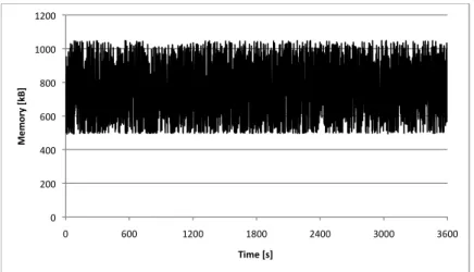
4.3 Memory consumption of a mobile TURN server caused by keepalives . . . 58
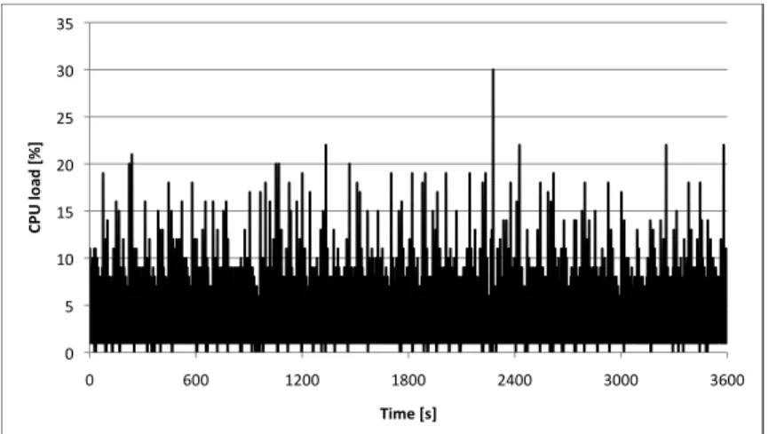
4.4 CPU load of a mobile TURN server caused by keepalives . . . 58
4.5 Battery consumption of a mobile TURN server caused by keepalives . . . . 59
4.6 Calculating loop . . . 61
4.7 Sending loop . . . 61
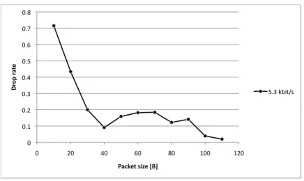
4.8 Drop rate on different packet sizes . . . 62
4.9 CPU load of a mobile TURN server caused by data relaying . . . 63
4.10 Memory consumption of a mobile TURN server caused by data relaying . . 63
4.11 Battery consumption of a mobile TURN server caused by data relaying . . 64
4.12 Drop rate with different number of clients . . . 65
4.13 CPU load of a TURN server caused by signaling data relaying . . . 66
4.14 Memory consumption of a TURN server caused by signaling data relaying . 66 4.15 Battery consumption of a TURN server caused by signaling data relaying . 67 4.16 CPU load of a STUN server caused by keepalives . . . 69
4.17 Memory consumption of a STUN server caused by keepalives . . . 69
4.18 Battery consumption of a STUN server caused by keepalives . . . 70
4.19 CPU load of a STUN client caused by keepalives . . . 71
4.20 CPU load of a TURN client caused by keepalives . . . 71
4.21 Memory consumption of a STUN client caused by keepalives . . . 72
4.22 Memory consumption of a TURN client caused by keepalives . . . 72
4.23 Battery consumption of a STUN client caused by keepalives . . . 73
4.24 Battery consumption of a TURN client caused by keepalives . . . 73
4.25 Call setup delays . . . 76
4.26 Components of call setup delay for mobile P2PSIP clients . . . 77
4.27 Components of call setup delay for wired P2PSIP clients . . . 78 4.28 Number of STUN messages sent during call setup by a mobile P2PSIP client 80 4.29 Number of STUN messages sent during call setup by a wired P2PSIP client 81
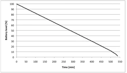
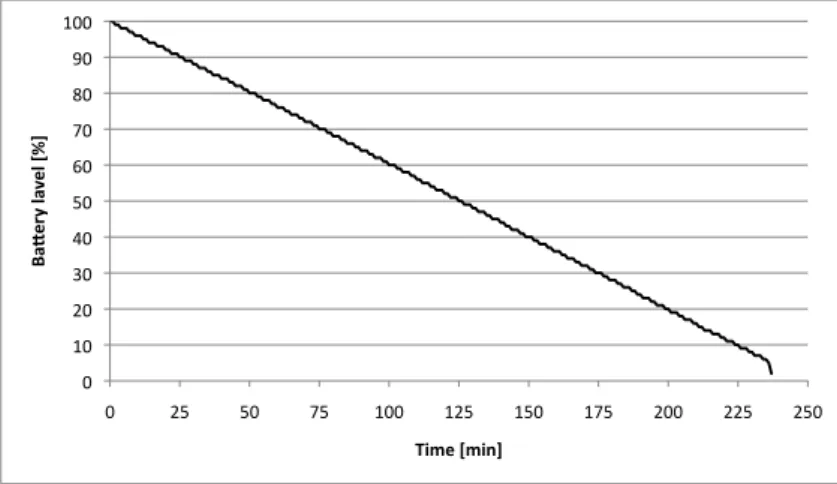
4.31 Battery duration and transmission interval . . . 83
4.32 Average memory consumption of a TURN server . . . 85
4.33 Average CPU load of a server with different number of clients . . . 86
4.34 Average CPU load of different scenarios with one connection . . . 86
List of Tables
2.1 STUN message types . . . 18
2.2 STUN attributes . . . 18
2.3 STUN message types for TURN . . . 21
2.4 STUN attributes for TURN . . . 22
2.5 Mapping and filtering behavior of existing NATs . . . 26
2.6 Probabilities for NAT types between two random hosts . . . 27
4.1 Mobile phone specifications . . . 51
4.2 Laptop specifications . . . 51
4.3 P2PSIP traffic model and parameters . . . 52
4.4 ICE parameters . . . 53
4.5 STUN message sizes . . . 54
4.6 TURN server with different number of clients (keepalives) . . . 60
4.7 TURN server with different number of clients (signaling data) . . . 67
4.8 STUN server with different number of clients (keepalives) . . . 68
4.9 STUN and TURN client with signaling data . . . 72
4.10 Maximum numbers of STUN and TURN clients . . . 73
4.11 Comparison of voice and signaling data relaying . . . 88
Introduction
The word ‘Internet’ was first introduced in the early 1980’s. Since then the Internet has changed tremendously, both in size and the way people communicate using it; not to men-tion its increased performance. At first, the use of Internet was primarily limited to a small number of users, such as scientists, universities, and the military. Therefore, the 32-bit In-ternet Protocol (IP) version 4 [2] address space with approximately four billion addresses was considered more than enough for future utilization – an assumption that turned out to be very wrong. Nowadays the Internet is accessible by almost everyone and nearly every-where. In addition, the number of different access devices has grown, varying from wired computers to handheld personal digital assistants (PDAs). As a result, the need for globally uniquely addressable devices has grown as well as the challenges in routing between these devices.
Network Address Translators (NAT) were devised as a short-term solution to the problem of IP address depletion and scaling in routing [48]. NATs are devices capable of sharing one or more globally unique addresses between multiple hosts. The hosts behind a NAT form a private network that uses internally unique private addresses making the private network also more secure. These private addresses can be reused within other private networks. Despite the fact that many long-term solutions were identified during the same time, such as larger IP address space, NATs have gained widespread popularity in the Internet [48, 22]. One reason for the increased popularity is their simplicity of deployment; only changes in the routers at the edge of the network are required [48].
Some of the drawbacks that NATs cause were known from the start, such as problems with end-to-end security mechanisms and applications using IP address information in the IP
packet payload, others have followed from the fact that all communication is no longer client-server based. In peer-to-peer (P2P) communications, a session can be initiated by either one of the communicating parties. Since any host is capable of acting as a peer, it is possible for peers to be located behind a NAT, which makes contacting them a bit more problematic. To help setting up a connection, peers often need to make use of a signaling channel, such as one created using the Session Initiation Protocol (SIP) [11].
The signaling channel is used for exchanging control messages, but it is inefficient for carrying data traffic, since it usually results in a possibly indirect path between the peers. NAT traversal is the way to work around the problems caused by NATs in peer-to-peer environments. Session Traversal Utilities for NAT (STUN) [44] and Traversal Using Relays around NAT (TURN) [43] are tools for other protocols to use to traverse NATs. How well the tools work depends on the characteristics of the NATs between the peers. STUN and TURN can be used as such, but they are usually used as part of a full NAT traversal solution, such as Interactive Connectivity Establishment (ICE) [42]. STUN is a mechanism that a host can use to discover its globally routable address that another host may try to use for contacting it. This address might be either an address on one of the host’s directly attached interfaces or an address assigned by the NAT. STUN tries to provide a direct path to the host, whereas TURN is used to provide a relayed path. Thus, when using the TURN protocol, a client can request a TURN server in the external network to relay data messages between the client and its peers. This solution is very likely to work, but it is not considered efficient due to the relaying costs. ICE is used to find the optimal path for communication, which means relaying messages only as a last resort.
P2P networks, such as Peer-to-peer Session Initiation Protocol (P2PSIP) networks, have to implement multiple protocols to keep the P2P overlay function. Due to the decentralized nature of a P2PSIP network a distributed database algorithm is needed for locating a peer with a particular data item within the network. Furthermore, a P2P signaling protocol is required for purposes of maintaining the network. SIP is used for enabling communication between the peers. Even though the network maintenance requires more complicated co-operation of peers than a simple client-server model, the efforts pay of since a P2P network is self-organized and more scalable.
In addition to computers, also mobile phones can have a NATed address. Even though the problem with NATs and the solution to the problem stay the same, there are other issues to be taken into consideration. The constraints of mobile phones relative to computers are well-known: limited memory, battery and processing power. An interesting subject for research is knowing whether these constrains are a limiting factor for the use of NAT traversal tools in mobile phones.
1.1
Objectives and Scope
The applicability of the ICE protocol as a NAT traversal solution has been shown in setups where the nodes running the protocol are computers [28]. The objective of this thesis is to examine the applicability of the protocol when computers are being replaced by mobile phones. The interest for the study arose as the need for NAT traversal in the context of mobile phones became apparent. To be able to provide meaningful results on the power consumption and the sufficiency of processing capacity of a mobile phone, an ICE protocol library was implemented for Java 2 Micro Edition (J2ME). Some measurements are also made in comparison to the protocol usage on computers. Our main focus is on establishing a phone call between wired and wireless peers in the presence of different type of NATs in a P2PSIP network of reasonable size. This makes it possible to compare the difference in call setup times for different NAT scenarios. Additionally, the performance of a mobile phone as a STUN and TURN client and server is measured.
Protocols intended to traverse NATs might also be usable for traversing other type of middle-boxes. However, regarding this thesis, those are out of scope. There is also a re-striction pertaining to the supported transport protocols: we only discuss NAT traversal for UDP-based traffic due to the multiple additional challenges related to TCP NAT traversal, and also due to the lack of standardized mechanisms for TCP NAT traversal [20]. Addition-ally, questions regarding the incentives of peers to act as relays in P2P networks are out of scope.
1.2
Structure
In this Chapter the subject area and its scope were briefly introduced, as well as the purpose and goal of writing the thesis. Chapter 2 provides a deeper insight to the topic of the thesis. Chapter 3 describes the implemented ICE prototype, including some experiences and chal-lenges concerning the implementation. Chapter 4 describes the prototyping environment and includes the actual measurement results. The chapter also analyzes the measurement results. In Chapter 5, we discuss the applicability of the NAT traversal protocols in mobile peer-to-peer networks based on the results presented in the previous chapter. Finally, in Chapter 6, we sum up the results and draw final conclusions.
Background
In this chapter we present the concepts of NATs, NAT traversal, and P2P communication. We start by introducing NATs and take a more detailed look at two of the most common NAT types. We will explain the advantages and disadvantages of NATs. Additionally, we present how NATs are classified based on their characteristics. Then we explain NAT traversal and cover some of the most relevant NAT traversal techniques in more detail. To show the importance of NAT Traversal in today’s Internet, we give a brief overview on the existence of different NAT types. The background on P2P communication includes an overview of Peer-to-Peer Session Initiation Protocol (P2PSIP) and how peer-to-peer net-working makes use of distributed hash tables, such as Chord. Moreover, we introduce two peer-to-peer signaling protocols: REsource LOcation And Discovery (RELOAD) and its predecessor protocol, known as Peer-to-Peer Protocol (P2PP). Finally, we briefly describe the basic capabilities of a mobile phone.
2.1
Network Address Translation
Network Address Translation is a method that enables IP address reuse. It is realized by placing a Network Address Translator (NAT) at the border of a local network with private IP addresses. It is the responsibility of the NAT to translate these locally unique addresses to globally unique addresses while accessing the external network. The NAT device maintains a table with private-public address mappings. Since private and public addresses have to differ for network address translation to function, the IP address space is divided into two parts. Private IP addresses used within a local network can be reused within any other local
network. The network address translation is done transparently to the end hosts. This means that a host behind a NAT sees as though packets it receives from the external network would have been designated to its own local node IP address already at the source of the message. Likewise, the external host does not know that packets it sent to an external address of the NAT are actually forwarded to a local host behind the NAT. The illusion is created by careful header manipulation done by the NAT. Header manipulation concerns at least the IP address, the IP checksum and TCP checksum (in case of TCP). Also certain type of Internet Control Message Protocol (ICMP) error messages, which include the original IP packet, require changes in their payload [16, 50].
The life cycle of a single NAT session consists of three phases. In the first phase, a local address gets an external IP address assigned to it. In static address assignment, a given host is configured to be always associated with the same public IP address when connecting to the external network. In the case of dynamic assignment, addresses are assigned dynam-ically, meaning that a host might receive different bindings at different times, and that a binding used by the host might be reused by other hosts after the session with the host in question has terminated. In the second phase, when the NAT receives a packet belonging to an already existing session, it needs to perform address lookup to confirm the existence of the session and modify the packet to keep the translation transparent. Finally, as the NAT assumes the session to have finished, it needs to unbind the address association. The address may now be freely used by other sessions. To prevent a premature unbinding from happening, hosts need to keep the binding alive via regular transmissions. [50]
Corporate network Internet ISP network PC PC LaptopLaptop PC PC NAT NAT PC PC PC PC Base station Base station Cell phone Cell phone NAT NAT NAT NAT Laptop Laptop Server Server
Some typical NAT scenarios are shown in Figure 2.1. A company uses private addressing to hide its addresses and address structure from the external network. Since it is a company network, most of the communication is internal, meaning that an address translation does not even always take place [16]. A NAT can also be used to block unknown traffic from entering the network. Another typical scenario is a user at home wanting to gain access to the Internet via a laptop and a PC simultaneously, but having only one IP address available. By connecting both of the devices to the Internet through a NAT makes it possible to share a single public address between both of them. In addition, when a mobile phone connects to the network, it can get an address assigned to it that is only unique within the cellular network it resides in. NATs come in many flavors, but in the following subsections only traditional NATs, as being the most common ones, are presented in more detail. Traditional network address translation can be based on either basic network address translation or Network Address and Port Translation (NAPT).
2.1.1 Basic Network Address Translator
In Basic Network Address Translation (Basic NAT), a NAT has a set of public IP addresses to be shared by the hosts behind the NAT. The translation applies only to the IP addresses. The maximum number of hosts being able to simultaneously access the public network is equal to the number of public IP addresses that the NAT has. If there are more hosts, access to the Internet cannot be guaranteed. All sessions initiated from the same host use the same mapping. Taking advantage of static address assignment, certain hosts can have guaranteed access at all times. [48]
Private network Host A 10.0.0.1 Host B 10.0.0.2 Host C 108.37.178.14 Public network Basic NAT Src: 10.0.0.1 Dst: 108.37.178.14 Src: 10.0.0.2 Dst: 108.37.178.14 Src: 183.54.114.2 Dst: 108.37.178.14 Src: 183.54.114.3 Dst: 108.37.178.14
Figure 2.2 shows the operation of a Basic NAT. Two hosts, Host A (10.0.0.1) and Host B (10.0.0.2), which are located in the same private network, both want to set up a connection to Host C (108.37.178.14) in the public network. Initially, neither of the hosts has any ongoing sessions. As the first outgoing packets traverse through the NAT, the NAT assigns the hosts new addresses (183.54.114.2 and 183.54.114.3) that are used outside the private network. The assigned address does not depend on the destination address of the packet. The same translation is used for all subsequent packets belonging to the same host until all of its sessions have finished. After that the address can be used by other hosts.
Private network Host A 10.0.0.1 Host B 10.0.0.2 Host C 108.37.178.14 Public network Basic NAT Src: 108.37.178.14 Dst: 10.0.0.1 Src: 108.37.178.14 Dst: 10.0.0.2 Src: 108.37.178.14 Dst: 183.54.114.2 Src: 108.37.178.14 Dst: 183.54.114.3
Figure 2.3: Basic NAT with return traffic
Figure 2.3 shows the operations that the Basic NAT makes for the return traffic. The transla-tion is performed by replacing the destinatransla-tion address of the packet with the private address. As Host C receives packets, it does not need to know that the addresses it sees as source addresses are actually public addresses assigned by the NAT. This is why it sends its return packets back to the assigned public addresses just like to any other node with a public ad-dress. Regarding basic NAT, the translation done by the NAT applies to the IP address and the IP checksum of the IP header, as well as the checksum in the TCP and UDP headers (if used). Likewise, modifications to the ICMP error messages concern only the IP address and checksum parts in the payload. [48]
2.1.2 Network Address and Port Translator
In Network Address and Port Translation (NAPT), the translation is applied to the IP ad-dress as well as the transport layer identifier (i.e., port number) part of the packets. The advantage of this is that only one public IP address is needed to enable multiple hosts to
simultaneously access the public network. Different hosts and the different sessions on the same host are distinguished by assigning them different transport layer identifiers. The services supported by a NAPT router are restricted to UDP, TCP and ICMP query sessions.
Private network Host A 10.0.0.1 Host B 10.0.0.2 Host C 108.37.178.14 Public network NAPT Src: 10.0.0.1:5000 Dst: 108.37.178.14:160 Src: 10.0.0.2:5000 Dst: 108.37.178.28:160 Src: 183.54.112.3:6000 Dst: 108.37.178.14:160 Src: 183.54.112.3:6001 Dst: 108.37.178.28:160 Host D 108.37.178.28
Figure 2.4: NAPT with outbound traffic
Figure 2.4 presents two ongoing sessions through a NAPT. Hosts A (10.0.0.1) and B (10.0.0.2) are in the private network and hosts C (108.37.158.14) and D (108.37.178.28) are in the public network. Host A has set up a connection with Host C and Host B similarly with Host D using the same transport identifiers as source and destination ports. The figure shows the translations that take place for the outgoing packets of the two ongoing sessions. Since NAPT has only one single address to share, both sessions have the same public address as source after the translation. However, the packets have different source ports to distinguish that they belong to different hosts and sessions (183.54.112.3:6000 and 183.54.112.3:6001).
Private network Host A 10.0.0.1 Host B 10.0.0.2 Host C 108.37.178.14 Public network NAPT Src: 108.37.178.14:160 Dst: 10.0.0.1:5000 Src: 108.37.178.28:160 Dst: 10.0.0.2:5000 Src: 108.37.178.14:160 Dst: 183.54.112.3:6000 Src: 108.37.178.28:160 Dst: 183.54.112.3:6001 Host D 108.37.178.28
Figure 2.5 shows how the translation is performed for the return traffic. The translation is done by replacing the destination address and port with the corresponding private address and port.
In case of NAPT, translating the IP address and the IP checksum of the IP header, as well as the checksum in the TCP and UDP headers is not enough. In addition, the TCP/UDP ports of the TCP and UDP headers must be modified. Also the modifications in the payload of an ICMP error packet must be extended to cover port modifications. [48]
2.1.3 Benefits of Network Address Translation
One of the advantages is allowing multiple hosts to share a single IP address for accessing the Internet, which naturally slows down the IP address depletion. However, NATs might also be useful for other reasons, such as privacy. The fact that connections cannot be initi-ated from the outside provides privacy for the internal network, and the actual addresses of the private hosts are usually not seen in the external network. [48]
Moreover, there is no need to change the internal addresses if the outside topology changes. A NAT can take care of the changes in a centralized way. Another benefit comes from is its simple deployment. The installation requires only changes to the address translation router. For hosts and other routers the translation is entirely transparent. [48]
A private network does not have to be geographically located in the same place. This is common with corporate networks that are spread to different locations along with the of-fices. To avoid the need of address translation, it is possible to share the same private address space between the separately located corporate networks. Since the packets have to traverse via the external network, where the private addresses are invalid, NATs encap-sulate the packets inside an IP packet that uses externally available addresses. From the private hosts point of you, all the hosts belong within the same private network. NATs have one address especially for the encapsulation. This type of network is called a backbone-partitioned stub [16]. In case of virtual private networks (VPN), the tunneled packets need to be encrypted to ensure privacy. [50]
2.1.4 Drawbacks of Network Address Translation
Network address translation violates some very fundamental architectural principles of the Internet. First of all, it breaks the end-to-end model by moving intelligence from the edge to
the core network. NAT also breaks the concept of fate-sharing by reducing robustness. Fate-sharing states that only an end point itself can destroy a state of its own. The principles also refer to the concept of “transparency”, which means unaltered communications between the end points using unique labels. Breaking the principles is not only a principle level issue, but incurs some practical drawbacks. By making all communications flow through the NAT creates a single point of failure. This could be avoided by using multiple NATs, but it would cause further challenges, like timely communication of the state and routing related failures. [12, 22]
One of the disadvantages with NATs are the complications they cause on several protocols. The problem is that some protocols include IP address or port information into the payload of IP packets. This breaks the fundamental idea of transparency that NATs are supposed to provide. Some of the protocol complications can be worked around by extending NATs to offer protocol specific aid by means of Application Level Gateways (ALG), others will fail anyway. But since the goal should be the ability to add new applications at end points with-out requiring changes to the infrastructure, adding ALGs increases the complexity. When using ALGs, application updates are required to multiple locations and applications need to be multiplexed. In addition, debugging gets more complicated. One of these protocols with complications is Session Initiation Protocol (SIP), which exchanges address and port infor-mation in the payload of the packets it sends. One example of a protocol unable to work through NATs as such is IPsec, since one of its explicit purposes is to detect alterations to the IP packet header by encryption. The problem with IPsec can, however, be solved with NAT-T (NAT Traversal in the Internet Key Exchange). Moreover, some protocols require retaining the same mapping for multiple sessions. However, a NAT cannot know that this is required, since it is designed to recycle addresses between different hosts and different sessions. [22, 16, 24, 50]
NAT, ALG and firewall work together to achieve an even more secure private network. If the NAT router is part of the trusted boundary, it can be used to implement IP security by serving itself as the other end of the tunnel. For example, ALGs can be used for checking that the payload or header of a packet does not include private IP addresses. The firewall filter can be used to drop such packets. It is also good to keep in mind that a NAT itself can be a target of an attack. This is why a NAT should use protection mechanisms similar to a server. [50]
One disadvantage closely related to the subject of this thesis are the challenges with peer-to-peer applications. Most of the NATs in use have been designed for client-server based communications, where the other node acts as a server in the external network and
connec-tions to it are initiated by a client either in private or public network. In P2P communica-tions, there is no clear distinction between a client and a server. Communication can be initiated by either of the communicating parties. Additional problems are due to the variety of different NATs. Different NATs use different binding as well as filtering rules. Another problem is that the hosts inside the private network have no externally visible addresses for the hosts outside to contact. Therefore, the addresses to contact have to be communicated via a signaling protocol, like SIP. NAT traversal takes care of finding the best working path between the peers based on the signaled addresses. [49, 24]
Even though network address translation is compute intensive, it is not necessarily a prob-lem. Especially as long as the NAT device is able to process packets at a higher speed than the transmission speed the line is able to achieve. NAT uses an effective checksum adjustment algorithm, since every packet needs to be translated. [24]
2.2
NAT Classification
To understand the different circumstances that NAT traversal is supposed to cope with, there is a need to classify the different NAT behaviors. The following sections clarify the properties of NATs by classifying them based on mapping, filtering and port assignment behavior. The firewall specific settings that might inhibit communications do not belong as part of the NAT classification. [4]
2.2.1 Mapping Behavior
Every time a private host initiates a new session to a host in the public network it gets a public address and port assigned to it (assuming NAPT). The assigned address and port are used for translating all the subsequent packets belonging to the same session. Mapping behavior is used to describe the different rules for mapping a private address and port into a public IP address and port. Even if different sessions would originate from the same source, it does not guarantee that the same mapping will be used. In fact, it also depends on the endpoint the packets are destined to. Thus, the mapping behavior can be divided into endpoint-independent mapping, address-dependent mapping, and address and port-dependent mapping. [4]
Endpoint-independent mappingmeans that the NAT re-uses the same mapping for all
and port. Figure 2.6 shows an example of endpoint-independent mapping. In the figure, the NAT uses the same mapping for both of the sessions from the same origin, no matter what the address or port of the external sessions endpoint is.
Private network Host A 10.0.0.4 Host B 128.47.86.5 Public network NAT Host C 128.47.86.9 Src: 10.0.0.4:150 Dst: 128.47.86.5:400 Src: 173.30.45.2:3000 Dst: 128.47.86.9:450 Src: 173.30.45.2:3000 Dst: 128.47.86.5:400 Src: 10.0.0.4:150 Dst: 128.47.86.9:450
Figure 2.6: Example of endpoint-independent mapping
Address-dependent mappingmeans that the NAT re-uses the same mapping for all packets
originating from the same address and port to the same destination address, regardless of the port used. Figure 2.7 shows the same situation as Figure 2.6, except that in this case, the NAT assigns a different mapping since the session endpoints have different addresses.
Private network Host A 10.0.0.4 Host B 128.47.86.5 Public network NAT Host C 128.47.86.9 Src: 10.0.0.4:150 Dst: 128.47.86.5:400 Src: 173.30.45.2:3001 Dst: 128.47.86.9:400 Src: 173.30.45.2:3000 Dst: 128.47.86.5:400 Src: 10.0.0.4:150 Dst: 128.47.86.9:400
Figure 2.7: Example of address-dependent mapping
Address and port-dependent mapping means that the NAT re-uses the same mapping for
packets originating from the same address and port only if the destination address and port are the same. Figure 2.8 shows two sessions between same hosts, however, with two different mappings, because the sessions use different ports on the external hosts.
Private network Host A 10.0.0.4 NAT Src: 10.0.0.4:150 Dst: 128.47.86.5:400 Src: 10.0.0.4:150 Dst: 128.47.86.5:401 Host B 128.47.86.5 Public network Src: 173.30.45.2:3000 Dst: 128.47.86.5:400 Src: 173.30.45.2:3001 Dst: 128.47.86.5:401
Figure 2.8: Example of address and port-dependent mapping
2.2.2 Filtering Behavior
Filtering behavior is used to describe the filtering rules applied to incoming packets on an external address and port of a NAT. The criteria for the filtering is based on filtering rule defined for an internal and external endpoint pair. The rule can be based on either endpoint-independent, address-dependent, or address and port-dependent filtering. [4]
Whenendpoint-independent filteringis applied, all messages destined to an internal address
and port with a mapping are forwarded. The external address and port used for sending a packet does not effect the filtering.
In Address-dependent filtering, only packets originating from the same external address
where the internal host has already sent packets to are accepted. This means that the external host may use any source port for reaching the internal host.
Address and port-dependent filteringmeans that only packets originating from an external
address and port, that the internal host has already sent packets to, are accepted. All other packets are rejected.
2.2.3 Port Assignment Behavior
Port assignment behavior describes the rules that NATs use for assigning ports. [4]
When a NAT supports port preservation, it means that a NAT tries to use the same port for the assigned external address as is used for the private address. In case that port is already assigned for another mapping, a port collision occurs. It is up to the NAT how such a collision is handled; it can either override the previous mapping, assign a different port or
use the same address with a different external address (in case a NAT has multiple external addresses to choose from and one of them is unused). If a NAT usesport overloading, most applications will fail, since port preservation is always used despite of possible collisions. If port preservation is not supported, a NAT does not try to make any efforts in preserving a port. This is known as the “No Port Preservation” -behavior.
2.2.4 Hairpinning Behavior
A NAT is said to support hairpinning, if two hosts behind the same NAT are capable of communicating with each other using the public addresses assigned by the NAT. The Figure 2.9 shows an example of a NAT that supports hairpinning. Host A sends a message to host B using B’s public address, and the NAT relays the message to reach its destination. The figure shows the relevant translations.
Private network Host B Host A Public network NAT Src: A:a Dst: C:c2 Src: C:c1 Dst: B:b Src: C:c1 Dst: C:c2 C:c1 A:a B:b C:c2
2.3
NAT Traversal
With the advent of peer-to-peer applications, such as file sharing, Voice over IP (VoIP) and online gaming, the need for NAT traversal became apparent. Some applications rely on a central server to maintain a list of the connected hosts and the resources they have, while the actual data traffic is transmitted directly between the hosts. A direct communication is preferred in order to reduce transmission latency. Nowadays, a popular alternative is creating an entirely decentralized P2P network that is managed in collaboration between the peers, with no or little involvement of servers.
As described earlier, the problem with NATs is that hosts behind a NAT, without a public address assigned to them, can only be contacted by hosts within the same private network. Even if a host would have a public address assigned to it, it depends on the type of the NAT whether an incoming connection is accepted or not. Further, NATs were not until recently standardized, so one workable solution for all situations is not achievable [49, 4]. Consequently, the requirements for P2P communication work badly with NATs. But due to the popularity of P2P applications and the generality of NATs, several NAT traversal techniques have been developed. Almost all connection attempts to a private network are inhibited, unless there are static bindings. The Internet’s architecture is designed to work for client-server based communications where all the connections are initiated by the client and servers are located in the public network. However, peer-to-peer communications is not as straightforward in the presence of NATs. Peer-to-peer communication requires direct connections that can be initiated by either of the peers. [49]
NAT traversal is a collection of different mechanisms to create connections through dif-ferent type of NATs. Since the type of NATs is not known by the endpoints, multiple mechanisms may need to be tried out before finding a working one. One simple and prac-tical technique for UDP that many NATs support is known as “UDP Hole Punching”. Hole punching does not require any changes to be made to the infrastructure, instead it tries to work around the security policies of most NATs. UDP hole punching makes use of a well-known rendezvous server for setting up a direct peer-to-peer UDP session. By means of a rendezvous server it is possible to know if a client is behind a NAT or not by comparing the address that the server sees the client is using with the address the client thinks it is using. If the addresses differ, the client is behind a NAT. STUN is one example of a protocol that uses UDP hole punching for letting a client know its globally valid address and finding out whether it has a NATed address. [49]
The most reliable, but least efficient method is to relay messages between the peers via a server in the external network. This solution is likely to work since it makes the communica-tion look like a normal client-server communicacommunica-tion. Of course, with the basic assumpcommunica-tion of being able to connect to a server. This solution has, however, clearly and easily identifi-able drawbacks. Firstly, it consumes processing power and network bandwidth. Secondly, it induces additional latency between the communicating peers. But since it provides a guar-anteed solution, peers keep it as an option in case other attempts fail. TURN is an example of a protocol that provides such a relaying service. [49]
Despite the drawbacks of NATs, the need for NAT traversal is likely to remain for a long time. NATs are useful for the incremental deployment of IPv6 [15] addresses in translating between IP version 4 and version 6 addresses [22]. Additionally, to fully upgrade an existing infrastructure to support IPv6 services takes time [3]. Even after a full integration of IPv6, the need for NAT traversal will still remain; NATs are not the only type of middleboxes that need to be traversed, there are also other types of middle-boxes that benefit from using it, such as firewalls. Besides, even if more than enough IP addresses would be available, the benefits of private networks still make network address translation a desirable feature.
2.3.1 STUN
Session Traversal Utilities for NAT (STUN) is a protocol that a host can use to discover its globally routable address. This is done by sending a request to a server in the public network to learn the address that the server sees as the address of the client. This is called the (server) reflexive transport address. The returned address might be an address on one of the client’s directly connected interfaces or it might be an address assigned by a NAT. A client knows the address on its directly connected interface. Thus, if this address differs from the one returned by the server, the client knows it is behind a NAT. Depending on the type of the NAT, a host in the public network could be able to use the returned address for contacting the host behind the NAT. STUN also provides a mechanism to keep the binding on the NAT alive. This solution works properly for NATs performing endpoint-independent mapping [54]. STUN is not a complete NAT traversal solution in itself, but works as part of a full solution. [44]
Figure 2.10 shows a possible STUN configuration. The host behind a NAT is called a STUN client, and the server on the external side is called a STUN server. Communication between the STUN agents is possible since STUN is a client-server protocol. With STUN agents we refer to entities implementing the STUN protocol. There are two types of STUN
Private network 1 STUN Client Public network NAT 1 Private network 2 NAT 2 STUN Server Reflexive Transport Address Host Transport
Address STUN Server
Address
Figure 2.10: Example of a STUN configuration
transactions: request/response and indication. In a request/response transaction the client sends a request to the server and the server replies with a response. Indication messages are never replied to. STUN transactions are distinguished via a transaction ID. The transaction ID is a randomly chosen 96-bit identifier used to associate requests with responses. The transaction ID is included in the fixed 20-byte header of a STUN message alongside with the message type, length and magic cookie. A 32-bit magic cookie value is one of the ways used to distinguish STUN messages from other messages. The format of a STUN message is shown in Figure 2.11.
Magic Cookie
Message Length 0 0 STUN Message Type
Value (variable)
Length Type
Transaction ID (96 bits)
Figure 2.11: Format of a STUN message including a STUN attribute
The STUN message type field is a combination of the method and class values. A single method, called Binding, is needed for the basic STUN functionality to work. The message classes are request, success response, failure response and indication. The different STUN message types are summarized in Table 2.1. Following the header, a message can have
Table 2.1: STUN message types Message type Description
Binding request Client requests for a Binding response Binding success response Includes the reflexive transport address Binding error response Includes the type of the detected error Binding indication Keeps the binding on the NAT alive
zero or more attributes specified by the method or the usage. In the Figure 2.11, the header is followed by a single attribute (marked in grey). The STUN protocol defines a generic message format that can be extended to provide additional features for other protocols using STUN for NAT traversal. The STUN attributes are listed in the Table 2.2 below.
The basic STUN functionality involves the client sending a Binding request to the server and the server replying with a Binding response, that includes a XOR-MAPPED-ADDRESS at-tribute containing a combination of IP address and port, identifying the client as seen by the server on the public network. This way the client learns its reflexive transport address. Since UDP is not a reliable transport protocol, STUN request might need to be retransmitted. The retransmission timeout doubles after every retransmission starting with a 500 ms timeout. A maximum of 7 retransmissions is used, in case no response is received before that. Af-ter a successful request/response transaction, the client starts sending Binding indication messages to the server address to keep the binding alive. The recommended frequency for Binding indications is 15 s. The binding on the NAT breaks after a while, if no messages are sent using the binding. The server does not need to be informed of the unbinding.
Table 2.2: STUN attributes Attribute type Description
(XOR-) MAPPED-ADDRESS Indicates a reflexive transport address
USERNAME Identifies the username and password combination MESSAGE-INTEGRITY Contains an HMAC-SHA1 of the message
ERROR CODE Used in Error response messages
REALM Used with long-term credentials
NONCE A random value used for replay protection
When receiving a message, a STUN agent first needs to confirm that the message in question is indeed a STUN message before further processing. If the message is a response message, the agent needs to check that the transaction ID of the received message matches one of the outstanding transactions. Some other checking might be necessary, such as checking the FINGERPRINT extension discussed below. Additionally, possible authentication mecha-nisms are checked if specified by the usage. In case of an error specified by the STUN protocol, an error response is sent. The type of error is announced in the ERROR-CODE attribute.
The FINGERPRINT mechanism is an additional mechanism for distinguishing STUN mes-sages from other mesmes-sages. It is needed when multiplexing multiple protocols using the same transport address. When utilized, an agent adds the FINGERPRINT attribute to the messages it sends. STUN provides also authentication and message-integrity mechanisms, known as the short-term credential mechanism and the long-term credential mechanism. When using short-term credentials, another protocol is needed for exchanging a username and a password. The username and the password are applicable only for the duration of the media sessions, which makes the credentials time-limited. When forming a request or an indication the USERNAME and MESSAGE-INTEGRITY attributes must be included, whereas a response message must only include the MESSAGE-INTEGRITY attribute. The message integrity is a value computed using the password exchanged earlier.
The long-term credentials rely on long-term username and password credentials. They are called long-term since they stay valid until a user is no longer a subscriber of the system or they are changed. Replay attacks are prevented by using realm and nonce values. Initially, the client sends a request without any credentials or integrity checks. The server rejects the request by providing the user a realm and a nonce. For the next request, the client adds the username, realm and the nonce it just received. Also a message-integrity is included providing an HMAC (Hash-based Message Authentication Code) over the entire request, including the nonce. The server checks the values, and if approved, the message is authen-ticated. If the nonce is no longer valid the whole procedure is repeated by rejecting the request and providing a new nonce. Indications are not protected by long-term credential. All responses sent by the server should include the message-integrity attribute computed using the username and password used to authenticate the request, but the username, realm, and nonce attributes should not be included.
2.3.2 TURN
There are situations in which a direct connection between hosts behind different NATs is impossible, especially if a NAT uses address or address and port dependent mapping [54]. In such cases, it is necessary to relay the communication via an external intermediate node. Traversal Using Relays around NAT (TURN) [43] is a protocol that provides a relaying service via a TURN server. The relaying service of TURN can be used as such to guarantee communication between peers or as part of ICE to make traversal of NATs more optimized – using relaying only as a last resort. TURN is an extension to the STUN protocol, that allows a client to allocate an address on the TURN server using a new method type called Allocate. Private network TURN Client NAT Public network TURN Server Client’s Reflexive Transport Address Client’s Host Transport Address TURN Server Address Relayed Transport Address Peer Peer Transport Address
Figure 2.12: Example of a TURN configuration
Figure 2.12 shows a possible TURN configuration. The client sends an Allocate request to the server and the server replies with an Allocate response including a XOR-MAPPED-ADDRESS (see Section 2.3.1) and a XOR-RELAYED-XOR-MAPPED-ADDRESS attribute that contains a relayed transport address. The relayed transport address is a combination of IP address and port on the server that peers can use for contacting the client. The Allocate request and response messages can include additional attributes to describe the allocation. TURN clients send both STUN and data messages to the TURN server address. The TURN server sends the data messages forward to the clients’ peers using the clients’ corresponding re-layed transport address. Another method type is called Refresh, and it can be used either to refresh an existing allocation, update the expiry time of an allocation, or to delete an allocation. All the new TURN related STUN message types (excluding error responses)
Table 2.3: STUN message types for TURN Message type Description
Allocate request Makes an allocation on the server
Allocate response Includes the reflexive and relayed transport address Refresh request Refreshes the allocation
Refresh response Acknowledges the Refresh request CreatePermission request Permits a peer to send data for the client CreatePermission response Acknowledges the CreatePermission request ChannelBind request Requests to send ChannelData messages ChannelBind response Acknowledges the ChannelBind request
and attributes are collected in the Tables 2.3 and 2.4. Since a relayed transport address un-ambiguously defines a client’s reflexive transport address and the used transport protocol, relaying the messages from the client’s peers to the corresponding client is straightforward. However, the client must beforehand approve the peer, whose messages are to be forwarded. This is done by the client sending a CreatePermission requests to the server specifying the permitted IP addresses as XOR-PEER-ADDRESS attributes in the message. The lifetime of a permission is 300 s (= 5 min) and it can be refreshed by retransmitting the CreatePer-mission request.
When sending an Allocate request, the client must choose a currently unused transport address for sending the message to the server transport address. The only obligatory at-tribute to be added to the allocate request is the REQUESTED-TRANSPORT atat-tribute that specifies the transport protocol to be used. When receiving an Allocate request the server checks the credentials, that the requested allocation does not already exist, and that the REQUESTED-TRANSPORT attribute is included. After this any additional attributes might be checked. If all checks are passed, an allocation is created. A response message sent from the server to the client includes, in case of a success response, the relayed trans-port address, lifetime of the allocation, unique identifier for the allocation on the server, and the server reflexive transport address. TURN itself does not make use of the server reflexive transport address; it is included for the convenience of other protocols, such as ICE. The TURN specification recommends the use of long-term credentials for the authentication to avoid the need to negotiate new credentials for every session. Once the allocation is done, the allocation needs to be refreshed before the lifetime of the allocation expires. This
Table 2.4: STUN attributes for TURN Attribute type Description
XOR-RELAYED-ADDRESS Indicates a relayed transport address REQUESTED-TRANSPORT Specifies the desired transport protocol XOR-PEER-ADDRESS Specifies the address and port of the peer
DATA Consists of the application data
LIFETIME Represents the lifetime of the allocation CHANNEL-NUMBER Indicates the number of the channel
is done by sending a Refresh request. The lifetime of an allocation can be requested in the Allocate request and it can be modified in the Refresh request. It is up to the server to decide whether the requested lifetime is approved, and inform the client about the actual lifetime in the response. When a client no longer wishes to use an allocation, it sends a Refresh request with a LIFETIME attribute of value 0. Sending and receiving of data through the relay does neither refresh an allocation nor renew a permission. The time-to-expiry is by default 600 s (10 min).
Data can be transmitted in one of two ways between the client and its peers through the TURN server. The first uses Send and Data indications, and the second uses channels. When using the first way data is sent using a Send indication STUN message including two attributes: the DATA attribute including the data and the XOR-PEER-ADDRESS attribute including the address of the peer. Data is encapsulated in a Send or Data indication only between the client and the server. When the Send indication is received by the server, data is extracted and forwarded in a UDP datagram to the peer. To the opposite direction, as the server receives a data message on a relayed transport address, it places its content into the DATA attribute of a Data indication, puts the peer’s address into the XOR-PEER-ADDRESS attribute and forwards the message to the client.
Using channels produces less overhead. This results from using a new message format, known as ChannelData message, instead of the STUN message format. It uses a 4-byte header, that indicates the channel number, a value bound to a peer’s address to work as a ref-erence number. The binding is done by sending a ChannelBind request to the server, which includes an unbound channel number (CHANNEL-NUMBER attribute) and the transport address of the peer (XOR-PEER-ADDRESS attribute). After the binding is made, the client is able to send data to its peer by sending a ChannelData message to the server. Likewise, it is able to receive ChannelData messages on the channel from the server. Channel bindings
are always initiated by the client. All other messages, except for the ChannelData message, are STUN message formatted. Permissions are granted based on IP addresses and a per-mission for a peer to send data back to the client expires after 5 minutes. A perper-mission can be refreshed by repeating the ChannelBind (or CreatePermission) transaction. A channel binding lasts for 10 minutes unless refreshed.
2.3.3 Interactive Connectivity Establishment
Interactive Connectivity Establishment (ICE) [42] is a protocol developed by the Internet Engineering Task Force’s (IETF) Multiparty Multimedia Session Control Working Group (MMUSIC). It provides a complete NAT traversal solution by utilizing the functionalities of STUN and TURN. ICE was originally defined to be used by UDP-based multimedia communication protocols, but later has been extended to handle TCP transport protocols [39]. This work only focuses on ICE for UDP-based media. A host using ICE, known as an ICE agent, needs to know the address of a STUN or TURN server and to have a signaling path with the host it wishes to communicate with.
In the beginning of the ICE processing, an agent discovers its transport addresses, known as candidates, that are potential points for contacting it. An agent uses the mechanisms of TURN to learn its server reflexive transport address and relayed transport address. Each agent knows the transport addresses obtainable from its local interfaces. To establish ses-sions using an offer/answer mechanism, a signaling path is required between the peers. The signaling path is used for exchanging the candidates a peer has gathered, for example within SDP (Session Description Protocol) offers and answers. The candidates received from the other agent are known as peer candidates. An agent pairs up its own candidates and the can-didates of the peer and arranges them in a priority order, forming a list of possibly working candidate pairs. Then, the agent starts performing connectivity checks, which are done by sending checks on each candidate pair in priority order and at the same time replying to received checks. Checks are done by STUN Binding request transactions. When a check succeeds on a candidate pair, the pair is considered valid for communication.
One of the agents is controlling agent and the other one is a controlled agent. The agent in controlling role nominates one of the valid pairs for sending and receiving of media. This is done by performing a check on the chosen pair with a USE-CANDIDATE attribute added to the STUN request message. There are two approaches on nominating candidate pairs: regular nomination and aggressive nomination. In aggressive nomination, the USE-CANDIDATE attribute is added to each check and the first check to produce a reply is
chosen for media. In regular nomination, the controlling agent nominates a valid pair in the valid list as soon as it meets its stopping criteria. The stopping criteria is entirely up to the controlling agent’s local optimization. As the controlled pair receives a STUN message including a USE-CANDIDATE attribute, it knows to use the pair in question for the media. ICE can be implemented either as a lite or full implementation. A lite implementation does not gather candidates, since it only uses the addresses from local interfaces. In addition to this, it does not generate connectivity checks. It simple responses to checks. A lite agent never takes the role of a controlling agent. The ICE lite version is implemented on agents that are directly connected to the public network, but want to support ICE. A full implementation, in addition to generating the checks, also implements some additional pro-cedures, such as detecting and repairing of role conflicts and discovering new peer reflexive candidates. A peer reflexive candidate identifies a peer as seen by the other peer. A full implementation uses triggered checks to speed up the ICE processing: if an agent receives a check on a pair that is not in succeeded state, it schedules a connectivity check on that pair.
Sometimes, a single ICE negotiation is used to establish connectivity for more than one transport layer port on a single transport address, for example, one for an audio and one for a video stream. Candidates and peer candidates for different media streams (i.e., compo-nents) are identified by different component IDs and only candidates and peer candidates with the same component ID are paired. To optimize the checks, in such a case, ICE im-plements a frozen algorithm based on the “similarity” of certain pairs. If two candidates are similar, they are said to have the same foundation – same transport address type and obtained from the same host candidate and STUN server, using the same protocol. The foundation of a candidate pair is simply the concatenation of the foundations of its candi-dates. The assumption behind the frozen algorithm is that checks performed on pairs with the same foundation value will end up with the same result for the checks. This makes it possible to optimize the order in which connectivity checks are performed despite of the priority order of the pairs.
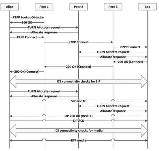
Example of ICE message flow
The message sequence diagram in Figure 2.13 shows an example message flow of an ICE session. The figure outlines the messages exchanged during the connection establishment phase and after the connection has been set up. The ICE agents are located in different private networks, however, they both use the same TURN server in the public network.
Controlling ICE Agent
10.0.0.1:150 NAT
Controlled ICE Agent 10.0.2.3:150 TURN Server 145.60.3.42:3478 NAT Allocate Request Allocate Response Allocate Request Allocate Response CANDIDATES Host 10.0.0.1:150 Reflexive 173.30.45.2:2010 Relayed 146.60.3.42:6080 CANDIDATES Host 10.0.2.3:150 Reflexive 108.37.178.28:160 Relayed 146.60.3.42:6081 SENDING AND RECEIVING OF INITIAL OFFER PERFORMING CONNECTIVITY CHECKS CHECK LIST CANDIDATE PAIRS Host – Host Host – Reflexive Host – Relayed Relayed – Host Relayed – Reflexive Relayed - Relayed Binding Req. Binding Request Binding Req. Binding Request Binding Response Binding Request Binding Response
Binding Request incl. USE-CANDIDATE Binding Response VALID LIST Reflexive – Reflexive VALID LIST Reflexive – Reflexive SELECTED PAIR Reflexive – Reflexive SELECTED PAIR Reflexive – Reflexive Binding Request Binding Request Send Indication Send Indication Binding Req.
Send Indication Binding Resp.
Binding Request VALID LIST Reflexive – Reflexive Relayed - Reflexive Send Indication Binding Response Data Ind. Binding Req. Binding Req. Binding Req. VALID LIST Reflexive – Reflexive Reflexive - Relayed APPLICATION LEVEL DATA Data Data Data Data Data Data Binding Indication Binding Indication Binding Req. Binding Resp. Binding Req. Binding Resp. Binding Req. Data Ind. Data Ind. Data Ind. Binding Resp. Binding Req. Binding Resp. Data Data Data Binding Ind. Binding Ind. Data Data Data Binding Req.
The agent on the left is in controlling role, so it first gathers its candidates and sends the initial offer. As the agent in controlled role receives the initial offer it likewise performs the candidate gathering procedure and sends its answer to the controlling agent. After the candidate exchange is done, ICE agents start performing the actual checks according to their check list. As the figure shows, the controlling agent might continue performing the checks as usual even after a candidate pair is added to the valid list. The valid list consists of candidate pairs that are considered valid for communication. An agent usually wants to make sure that none of the higher priority candidate pairs work before meeting its stopping criterion. An agent will ensure this via retransmission of yet unanswered Binding requests. In this example, the checks to the reflexive addresses either directly or via the TURN server work as long as permissions on the TURN server exist. On the other hand, transmissions to the host addresses will not work since the agents belong to different private networks. As soon as the stopping criterion is met, the highest priority valid pair gets nominated by sending a Binding request with an USE-CANDIDATE attribute. After this the agents can start sending data using the selected pair, which in this case means using the reflexive addresses as transmission endpoints. Messages need to be sent regularly to keep the binding on the NAT alive; Binding indications are used if no data has been sent for a while.
2.4
Existence of Different NAT Types
Defining the type of an existing NAT is not straightforward due to the non-deterministic nature of some NATs. Non-deterministic nature means that a single NAT might behave differently depending on the prevailing conditions. For example, this is the case with some of port preserving NATs. As a host tries to use a port that is already in use on the NAT, it gets a different port assigned to it, and additionally ends up with a different mapping and/or filtering behavior. A NAT that does not change its mapping or filtering behavior under any circumstances, is referred to as a deterministic NAT. A NAT that can change
Table 2.5: Mapping and filtering behavior of existing NATs Endpoint Address Address and Port Independent Dependent Dependent
Mapping 92.31% - 7.69%