Mobility management for Wi-Fi
infrastructure and mesh networks
by
Zimani Chitedze
A thesis submitted in fulfillment for the Degree of
Master of Science
in the Faculty of Natural Science
Department of Computer Science
Supervisor: Dr WD Tucker
Declaration of Authorship
I, Zimani Chitedze, declare thatMobility management for Wi-Fi infrastructure and mesh networks is my own work, that it has not been submitted for any degree or examination in any other university, and that all the sources I have used or quoted have been indicated and acknowledged by complete references. Signed: Date:
Abstract
This thesis shows that mobility management protocols for infrastructure Internet may be used in a wireless mesh network environment. In this research Mobile IPv6 and Fast Handover for Hier-archical Mobile IPv6 are successfully implemented in a wireless mesh network environment. Two experiments were carried out: vertical and horizontal handover simulations. Vertical handover simulation involved a heterogeneous wireless environment comprising both wireless local area and wireless mesh networks. An OPNET Mobile IPv6 model was used to simulate the vertical han-dover experiment. Horizontal hanhan-dover simulation involved Mobile IPv6 and Fast Hanhan-dover for Hierarchical Mobile IPv6 applied in ns2 wireless mesh network. The vertical handover results show that MIPv6 is able to manage vertical handover between wireless local area and wireless mesh network. The horizontal handover results illustrate that in mesh networks, Fast Handover for Hierarchical Mobile IPv6’s performance is superior to Mobile IPv6. Fast Handover for Hier-archical Mobile IPv6 generates more throughput and less delay than Mobile IPv6. Furthermore, Fast Handover for Hierarchical Mobile IPv6 drops less data packets than Mobile IPv6. The simu-lations indicate that even though there are multi-hop communications in wireless mesh networks, the performance of the multi-hop routing may not play a big role in the handover performance. This is so because the mesh routers are mostly static and the multi-hop routes are readily avail-able. Thus, the total handover delay is not affected too much by the WMN hops in the paths for signaling message transmission.
Association of Computer Machinery
(ACM) Classification Keywords
C.2.2 [Computer Systems Organization]: Computer-communication networks - Rout-ing protocols; C.2.1 [Network Architecture and Design]: Wireless Communication / Network Communication
Acknowledgements
I would like to convey my gratitude to my supervisor, Dr. William D ”Chopper” Tucker, for his advice, encouragement, and support. He always believed in me, even when I doubted my own abilities.
I also wish to thank the members of Bridging Applications and Networks Group (BANG) at UWC Computer Science department, especially Mr Michael Norman, Ms Docas Zulu, Mr Isaac Kobo, Mr Seyi Poroye and Mr Muyowa Mutemwa. Their suggestions and comments were helpful. As a special note, I would like to thank Prof. I M Venter, who graciously supervised my Honours degree project and her additional guidance was invaluable to the completion of this work. I dont think I could have gone this far without her advice when I first enrolled at University of the Western Cape in 2008.
I would like to thank The University of the Western Cape Computer Science Department lectur-ers, administrators and staff for all their hard work and dedication, providing me the means to complete my Honours and MSc degrees and preparing me for a career as a computer scientist. I also would like to thank Max and Mercy Kubwalo for helping me settle well in Cape Town. Thoriso Seepi for being a good and punctual flat mate.
Special thank you goes to: Wisdom Chitedze
My brother, my mentor, my best friend - taken from us too soon. My heart is hurting as I write this note, I never thought Cancer will destroy your physical body but even though I am crying because of your passing, I know you are in Heaven with the almighty God. I dedicate this work to you. The last words you said to me were ” It could have been worse, do you see me worried?” I will cling to those words until we meet again, Rest in Paradise my one and only big brother.
Chitedze Family
All I can say is thank you very much for supporting and being patient with me while I pursue my dreams. Ken (dad), Hilda (mum), Wisdom, Annie, Ken Jr, Elsie, Keitero, Keevan and Nina-Kwan, You are the best family in the world.
Last but not least, I would like to thank God for allowing me to complete this study in good health.
And finally, a big thank you to my dear future wife for putting up with me the past four or so years. You are a good tag team partner who always makes me proud. I do not have the words to express how I feel, only I love you, Maggie!
Table of Contents
Page
Declaration of Authorship . . . iii
Abstract . . . v
Keywords . . . vii
Acknowledgements . . . ix
Table of Contents . . . xi
List of Figures . . . xv
List of Tables . . . xvii
List of Abbreviations . . . xix
Chapter 1 Introduction . . . 1
1.1 Background . . . 2
1.1.1 Mobility management . . . 2
1.1.2 Wireless mesh networks . . . 5
1.2 Motivation . . . 6
1.3 Research Question . . . 8
1.4 Thesis outline . . . 8
2 Related Work . . . 11
2.1 IPv6 mobility protocols . . . 11
2.1.1 Mobile IPv6 . . . 14
2.1.2 Hierarchical Mobile IPv6 . . . 16
2.1.3 Fast Handover for Mobile IPv6 . . . 17
2.1.4 Fast Handover for Hierarchical Mobile IPv6 . . . 20
2.1.5 Seamless Mobile IPv6 . . . 22
2.1.6 Related work . . . 23
2.2 Mobility management protocols in Wireless Mesh Networks . . . 24
2.2.1 Client-side transparency . . . 26
2.2.2 Intra-domain mobility support . . . 30
2.2.3 Inter-domain mobility support . . . 31
2.3 Summary . . . 32
3 Methods and experimental design . . . 35
3.1 Gaps and challenges . . . 35
3.2 Research questions . . . 36
3.3 Research method . . . 38
3.3.1 Quantitative research . . . 38
3.3.2 Experimental quantitative research . . . 39
3.4 Experimental design . . . 40
3.4.1 Vertical handover simulation . . . 41
3.4.2 Horizontal handover simulation . . . 47
3.5 Summary . . . 52 4 Results . . . 54 4.1 Vertical handover . . . 54 4.1.1 Throughput . . . 55 4.1.2 Delay . . . 56 4.1.3 Packet loss . . . 58 4.1.4 Discussion . . . 59 4.2 Horizontal handover . . . 61 4.2.1 Throughput . . . 61 4.2.2 Delay . . . 62 4.2.3 Packet loss . . . 63 4.2.4 Discussion . . . 64 4.3 Summary . . . 65
5 Conclusion and future work . . . 67
5.1 Conclusion . . . 67 5.2 Limitations . . . 69 5.3 Recommendations . . . 70
5.4 Future Work . . . 70 References . . . 73 Appendix
A SATNAC 2012 full paper . . . 79 B SATNAC 2011 full paper . . . 85 C SATNAC 2010 work-in-progress paper . . . 93
List of Figures
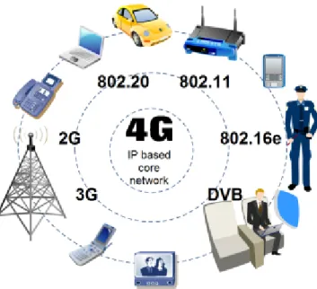
1.1 4G network . . . 2
1.2 Mobility managment hierarchy . . . 3
1.3 Horizontal handover . . . 4
1.4 Vertical handover . . . 4
1.5 Hybrid Wireless mesh network . . . 5
1.6 CISCO Visual Networking Index forecast . . . 7
2.1 IPv4 lifetime projection . . . 12
2.2 Mobile IPv4 overview . . . 14
2.3 Mobile IPv6 overview . . . 15
2.4 HMIPv6 overview . . . 16
2.5 FMIPv6 overview . . . 18
2.6 FMIPv6 Messaging . . . 19
2.7 FHMIPv6 overview . . . 21
2.8 S-MIP overview . . . 22
2.9 Topology used in [15] and [10] . . . 25
2.10 SMesh architecture . . . 27
2.11 SMesh example . . . 28
2.12 iMesh overview . . . 29
2.13 iMesh architecture . . . 30
3.1 Experimental quantitative research . . . 39
3.2 Experimental Design . . . 40
3.3 OPNET Flowchart . . . 42
3.4 WMN - WLAN simulation topology . . . 44
3.5 MIPv6 routing mechanisms . . . 47
3.6 ns2 flowchart . . . 48
3.7 Horizontal handover simulation setup . . . 50
4.1 Vertical handover traffic . . . 55
4.2 Vertical handover throughput . . . 56
4.3 Vertical handover delay . . . 57
4.4 Vertical handover packet loss . . . 58
4.5 Horizontal handover throughput . . . 62
4.6 Horizontal handover delay . . . 63
List of Tables
2.1 Comparison of IPv6 mobility management protocols . . . 23
2.2 Handover latency presented by Gwonet al. . . 24
2.3 Handover latency presented by Hsieh and Seneviratne . . . 25
2.4 WMN mobility management protocols . . . 32
3.1 Vertical handover simulation parameters . . . 46
3.2 Vertical handover scenarios . . . 46
3.3 Horizontal handover simulation parameters . . . 51
3.4 Horizontal handover scenarios . . . 52
4.1 Packet loss during horizontal handover simulation . . . 64
4.2 Average statistics of horizontal handover simulation . . . 65
4.3 Handover latency - mesh vs non-mesh . . . 65
List of Abbreviations
4G Fourth Generation
ACK Acknowledgement
ACM Association of Computer Machinery
AHRA Ad Hoc Routing Agent
AN Anchor Node
AODV Ad Hoc on Demand Vector
AP Access Point AR Access Router
BAck Binding Acknowledgement BDT Bi-Directional Tunneling BSS Basic Service Set
BU Binding Update
CAGR Compound Annual Growth Rate
CBR Constant Bit Rate CCG Client Control Group CDG Client Data Group CN Corresponding Node CoA Care-of-Address
DAD Duplication Address Detection
DHCP Dynamic Host Configuration Protocol DS Distribution System
DV Dependent Variable FA Foreign Agent
FBAck Fast Binding Acknowledgement
FBU Fast Binding Update
FHMIPv6 Fast handover for Hierarchical Mobile IPv6
FMIPv6 Fast Mobile IPv6
FNA Fast Neighbor Advertisement GPRS General Packet Radio Service
HA Home Agent
HAck Handover Acknowledgement
HAWAII Hando-Aware Wireless Access Internet Infrastructure HI Handover Initiation
HI-HAck Handover Initiation handover acknowledgment
HMIPv6 Hierarchical Mobile IPv6
IBSG Internet Business Solutions Group IBSS Independent Basic Service Set
ICANN Internet Corporation for Assigned Names and Numbers
IEEE Institute of Electrical and Electronics Engineers IETF Internet Engineering Task Force
IMS IP multimedia subsystem IP Internet Protocol
IPv4 Internet Protocol version 4 IPv6 Internet Protocol version 6 IV Independent Variables
kbps Kilobit Per Second
LBAck Local Binding Acknowledgment
LCoA Local Care-of-Address LTE Long Term Evolution
M2M Machine-to-Machine
MAC Media Access Control
MANET Mobile Ad Hoc Network
MAP Mobility Anchor Point Mbps megabit per second
MIPv4 Mobile Internet Protocol version 4
MIPv6 Mobile IPv6
MN Mobile Node
NAM Network Animator
NAR New Access Router
NAT Network Address Translation
NLCoA Next Link Care-of-Address
NOAH No Ad Hoc routing Agent
ns2 network simulator 2
OLSR Optimized Link State Routing
OPNET Optimized Network Engineering Tool
OSI Open Systems Interconnection
oTCL Object-oriented Tool Command Language pAR Previous Access Router
PLCoA Previous Link Care-of-Address
PPP Point to Point Protocol
PRD Pre-handover Route Discovery
PrRtAdv Proxy Router Advertisement
QoS Quality of Service
RCoA Regional Care-of-Address
RFC Request for Comments
RIPng Router Information Protocol next generation RO Route Optimization
RtSolPr Router Solicitation for Proxy SMIP Seamless Mobile Internet Protocol SSID Service Set Identification
TCP Transfer Control Protocol
UMTS Universal Mobile Telecommunications System VNI Visual Networking Index
VoIP Voice over Internet Protocol WDS Wireless Distribution System Wi-Fi Wireless Fidelity
WiMAX Worldwide interoperability Microvave Access
WLAN Wireless Local Area Network
WMN Wireless Mesh Network
Chapter 1
Introduction
This thesis shows that mobility management protocols for infrastructure-based wireless fidelity (Wi-Fi) may be applied to a wireless mesh network (WMN) environment. Mesh topology tends to be an unplanned graph and routes change dynamically. This thesis describes how Mobile IPv6 (MIPv6) and Fast Handover for Hierarchical Mobile IPv6 (FHMIPv6) were successfully imple-mented in a WMN environment. Mobility management in WMNs has still not been researched thoroughly, although a significant amount of research on infrastructure Wi-Fi and cellular net-works mobility management has been conducted [53]. Fourth generation (4G) networks will include all-IP (Internet Protocol) wired and wireless networks interworking together as heteroge-neous networks (see Figure 1.1) and promise to provide data rates up to a hundred times faster than current networks [53]. Its high capacity will be beneficial as it is projected that by 2015 overall global data traffic will grow up to 6.3 exabytes per month [11].
It is suggested that operators may be able to offload this traffic onto other IP networks such as WMNs by offering subscribers dual-mode mobile phones [11]. WMNs are attracting attention because of characteristics such as ease of installation and scalability, low cost network deployment, ease of network reconfiguration, reduction in wired links, robust communication, spectrum reuse efficiency and network capacity improvement [1]. Even though WMNs have turned out to be attractive and hold a great potential for 4G networks due to their capability to integrate with other wireless networks, there are still challenges that need to be addressed, particularly, MIPv6-based mobility management in a mesh environment [53]. Section 1.1 introduces mobility management and wireless mesh networks. Section 1.2 discusses the motivation for addressing these topics. Section 1.3 presents the research question and the overall approach of this investigation. Section 1.4 lays out the structure for the rest of the thesis.
Figure 1.1: 4G network - is projected to offer an all-IP network with facilities such as Internet, voice over IP and video at a high speed. Mobile devices such as laptops, smartphones and tablets are expected to be supported. It is being developed to accommodate existing technologies as well as new ones.
1.1
Background
The popularity of portable devices that support real-time data services, such as smartphones, laptops and tablets has caused the need for the convergence of different wireless access networks. Section 1.1.1 introduces mobility management and Section 1.1.2 presents wireless mesh networks.
1.1.1 Mobility management
Mobility management has become the most important ingredient in ubiquitous networks since the progress towards All-IP next generation heterogeneous networks. It provides seamless support of real-time and non-real-time services for mobile subscribers and facilitates connection mainte-nance for subscribers on the move when they change points of attachment. Futhermore, mobility management involves location management and handover management (see Figure 1.2)[2].
Location management allows the network to keep track of the location of the mobile clients and it involves two procedures: location registration and paging. In a location registration procedure,
Figure 1.2: Mobility managment - contains two components: location management and handover man-agement, and there are two types of roaming for mobile nodes (intra-system and inter-system)
the network is informed periodically by the mobile node communicating its current location which the network updates in the location database. After location management takes place, paging procedure requests the network to get information about the specific location of a mobile client so that data is delivered successfully [53].
Handover management is the procedure by which a mobile node (MN) keeps its connection active when it moves from one point of attachment to another. The handover procedure involves three stages:
1. Either the MN or the network triggers the initiation of handover. 2. Then the network finds new resources for the handover connection.
3. Finally, data flow control maintains the delivery of data from the old point of attachment to the new point of attachment with quality of service (QoS) [2].
Several protocols and mechanisms have been developed to support handover for multimedia ser-vices. Depending on the movement of the MN, the handover can be classified as horizontal or vertical. Horizontal handover refers to the ability to handover from one access point to the other within a homogeneous technology, for example handover from 802.11 to another 802.11 Wi-Fi subnet (see Figure 1.3).
Figure 1.3: Horizontal handover - handover between homogeneous access technology. For example, the MN moves from WLAN subnet to the other WLAN subnet.
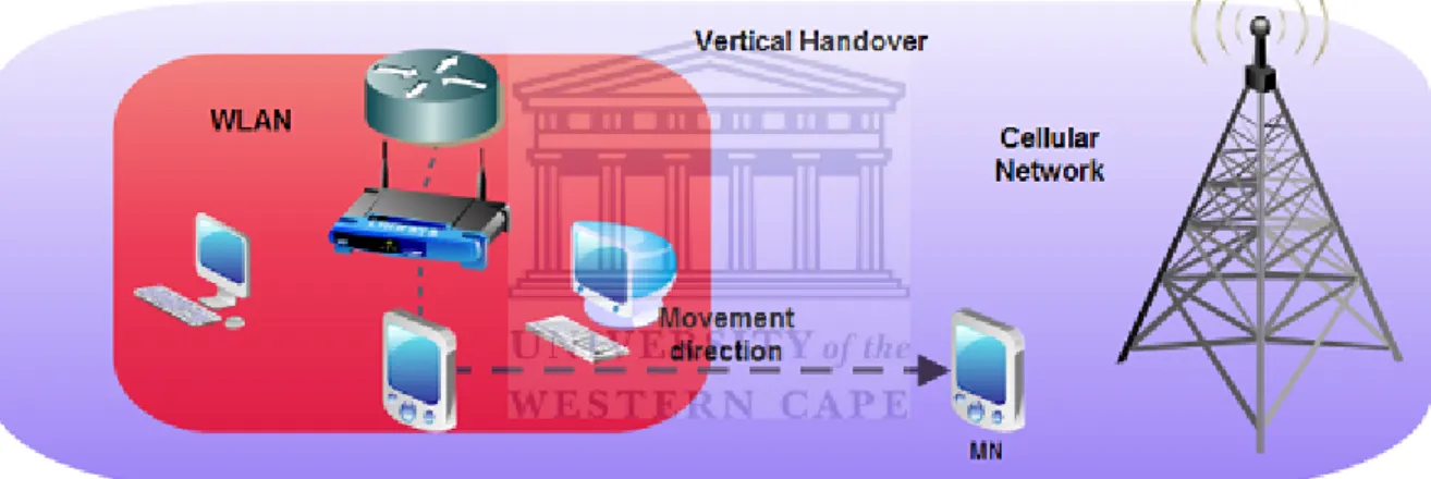
Figure 1.4: Vertical handover - handover across heterogeneous access technologies. For example, the MN moves from WLAN to cellular network.
On the other hand, vertical handover (see Figure 1.4) refers to the ability to handover across heterogeneous wireless technologies, for example, handover from any wireless local area network (WLAN) technology to General Packet Radio Service/Universal Mobile Telecommunication Sys-tem (GPRS/UMTS). Handover in heterogeneous networks is a much more complex matter. That is why it has been researched on different levels of the Open System Interconnection (OSI) refer-ence model protocol stack. Mobility protocols will be addressed in more detail in Section 2.1.
1.1.2 Wireless mesh networks
As the wireless communication technologies go through swift progression, there has been growing research in the area of WMNs [17]. WMNs are attracting attention because of their characteristics such as ease of and low cost network deployment, ease of network reconfiguration, reduction in wired links, robust communication, spectrum reuse efficiency and network capacity improvement [31].
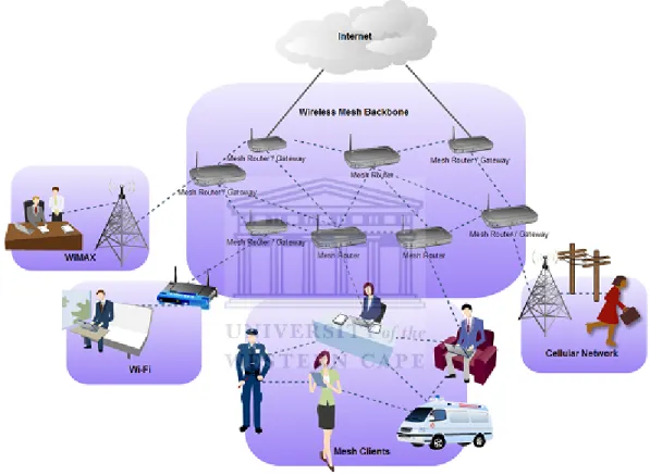
Figure 1.5: Hybrid WMN - combines infrastructure and client meshing. Mesh clients are able to access the mesh network through the mesh routers or through peer-to-peer communication with other mesh clients.
A basic WMN consists of mesh routers and mesh clients. There are three main types of WMNs determined by their structural design and deployment configuration: infrastructure mesh, client mesh and hybrid mesh. Infrastructure WMN architecture comprises mesh routers creating an infrastructure for clients. The mesh routers create links which configure and heal themselves, and
some mesh routers with gateway functionalities connect to the Internet through access routers (ARs). Client WMN architecture is a peer-to-peer mesh networking among clients. Mesh routers are not required in this architecture because mesh clients do all the routing and configurations themselves. Hybrid WMN (see Figure 1.5) architecture combines infrastructure and client mesh-ing. Mesh clients are able to access the mesh network through the mesh routers or through peer-to-peer communication with other mesh clients.
WMNs can be connected to other wireless communication networks such as Wi-Fi, worldwide interoperability microwave access (WiMAX) and cellular and networks (see Figure 1.5). Even though WMNs are attractive and hold great promise for 4G networks because of their integration with other wireless networks, there are still challenges that need to be addressed. One well known challenge is mobile IP-based mobility management in a WMN environment.
1.2
Motivation
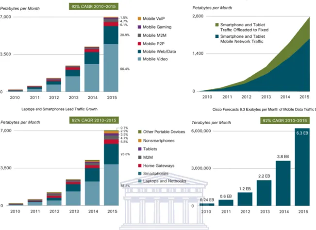
According to CISCO Visual Networking Index (VNI) forecast, total mobile data traffic is projected to grow to 6.3 exabytes per month by 2015 (see Figure 1.6). Mobile data traffic will grow at a compound annual growth rate (CAGR) of 92 percent from 2010 to 2015. The introduction of laptops, tablets and high-end handsets onto mobile wireless networks has caused the increase of traffic. These devices generate high traffic because of consumer content and applications offered, which were not supported by the previous generation of mobile devices. For example, a laptop can generate traffic equivalent to 515 basic-feature phones and a smartphone can produce as much traffic as 24 basic-feature phones. These devices will carry on generating high amount of traffic especially video, but new devices such as tablets and Machine-to-Machine (M2M) will begin to account for a large portion of traffic by 2015 (see Figure 1.6). Mobile video content will be the main cause of traffic growth through 2015 because it has higher bit rates than other content type. Video content will generate 4.2 exabytes of the 6.3 exabytes per month [11].
A survey conducted by Cisco’s Internet Business Solutions Group (IBSG) confirms that on average approximately 40 percent of total mobile data use is spent at home and approximately 35 percent of mobile Internet is used on the move, while the remaining 25 percent of mobile Internet use happens at work. The high percentage of using mobile Internet at home opens an
Figure 1.6: CISCO Visual Networking Index forecast - Cisco forecasts 6.3 exabytes per month of mobile data traffic by 2015. 39 percent of smartphone and tablet traffic will be offloaded by 2015. Mobile video will generate 66 percent of mobile data traffic by 2015. Laptops and smartphones lead traffic growth [11].
opportunity for operators to offload high mobile Internet traffic to other networks such as WLAN and WMNs. The operators may offer dual-mode mobile phones or mobile devices that support different wireless access networks, which can be used to roam across various wireless networks. For example, mobile data traffic may be offloaded to Wi-Fi when the subscriber is at home and roams to WMN when on the move. Without offloading the traffic, the combined amount of tablet and smartphone traffic would be 2.7 exabytes per month in 2015. While with offload, smartphone and tablet traffic will amount to 1.9 exabytes per month in 2015. [11].
1.3
Research Question
Mobility management is crucial for 4G network support and integrating all-IP based wireless networks. Mobility support can be provided using MIPv6 and its extensions. The objective of this research is to study MIPv6 mobility management schemes for WMN support in next generation heterogeneous all-IP based wireless networks. MIPv6 protocols for non-mesh IP networks provide a starting point for the invesigation. Handover management is investigated and since handover management consists of both vertical and horizontal handover, these two types of handover are explored in a WMN environment. Two simulations are developed: a WMN and a WLAN for the vertical handover prototype, while the horizontal handover prototype comprise WMNs only. This thesis addresses the following question: How do mobility managment protocols such as
MIPv6 and FHMIPv6 behave for handover with mesh networks? Furthermore, because
mobility management is affected by different variables, other sub-questions concerning handover for mesh networks include:
• How is throughput affected during handover?
• How much delay occurs during handover?
• How much packet loss is there during handover?
This research effort is concerned with MIPv6 based mobility management mechanisms in-cluding identifying the strengths and shortcomings of MIPv6. The handover performance short-comings of MIPv6 for WMNs are identified and validated through experimentation. A MIPv6 extension, FHMIPv6, addresses the deficiency of MIPv6 handover performance. This thesis eval-uates both protocols by means of discrete event simulations. The research is scoped to MIPv6 with particular focus over IEEE 802.11 WMNs. The reason for such focus is the excessive loss of performance experienced by MIPv6 when implemented in ad hoc networks. We can characterize the performance by answering the sub-questions for each protocol.
1.4
Thesis outline
The rest of the thesis is structured as follows:
Chapter 2presents related work concerning attaining low latency and packet loss during han-dover for WLANs and WMNs. The literature survey provides insight into mobility management in wireless networks using MIPv6 and its extensions. A section on IPv6 mobility protocols ex-amines mobile IPv6 mobility management protocols for WLANs. WMN client side transparency mobility management protocols are also summarized.
Chapter 3 identifies challenges and research gaps associated with mobility management. It also frames the research question and discusses the research method used to answer this research question. Furthermore, it presents the experimental design of this investigation, and introduces vertical and horizontal handover prototypes.
Chapter 4 presents and discusses handover results. Both vertical and horizontal handover prototypes are presented. The following performance metrics are addressed: throughput, delay and packet loss during handover.
Chapter 5 concludes the thesis and clarifies the limitations of this research effort. It also recommends what can be done to overcome the limitations. Finally, future research directions that could provide the next steps along the path to a practical and usable 4G heterogeneous network are suggested.
Appendices include published papers arising from this research. Final findings of this re-search were presented and published in Southern Africa Telecommunication Networks and Appli-cations Conference (SATNAC) 2012 (see Appendix A). Preliminary results of this research were presented and published in Southern Africa Telecommunication Networks and Applications Con-ference (SATNAC) 2011 (see Appendix B). The research proposal report was accepted for poster presentation at the same conference in 2010 (see Appendix C). All the papers in appendices are co-authored with the supervisor but this thesis is written exclusively by the author.
Chapter 2
Related Work
One of the objectives of mobility management is seamless support for real-time communication. This seamless support refers to achieving a sufficiently low latency and packet loss during han-dover. This chapter presents related work toward attaining these objectives for WMNs and WLANs. The literature survey is conducted to provide insight into mobility management in wireless networks using MIPv6 and its extensions. The existing work focuses on mobile IP-based mobility in wireless networks such as WLAN and Cellular. Section 2.1 examines mobile IPv6 mobility management protocols for WLANs. There is little research on mobile IP-based mobility in ad hoc networks such as WMNs. Section 2.2 looks at WMN client side transparency mobility management protocols.
2.1
IPv6 mobility protocols
Several mobility protocols have been proposed for managing IPv6 [1]. These protocols can be cat-egorized as micro-mobility and macro-mobility protocols. In micro-mobility, an MN moves within a given domain between subnets and engages in intra domain handovers [43]. Micro-mobility so-lutions include cellular IP [5] and handoff-aware wireless access Internet infrastructure (HAWAII) [42]. Cellular IP, from Columbia University and Ericsson Research supports paging and several handover techniques and optimization. Host location information is updated regularly using pack-ets, to minimize signaling. However, cellular IP relies on MIP to support global mobility, and has a limitation to support heterogeneous mobility between different domains [49]. HAWAII, from Lucent Technologies, also relies on MIP for inter-domain mobility. HAWAII is not a standalone solution but extends MIP to provide intra-domain mobility with QoS support. HAWAII leverages MIP to enable QoS mobility [41].
In macro-mobility, an MN moves from one administrative domain to another administrative
domain, and engages in inter domain handovers. Mobile IP is the most widely used protocol for macro-mobility management.
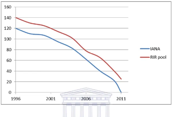
Figure 2.1: IPv4 lifetime projection - The graph shows the decline of available IPv4 spaces in /8s. ICANN (Internet Corporation for Assigned Names and Numbers) gave out the last block of IPv4 addresses and the remaining addresses will be assigned as early as 2012 (http://www.icann.org/).
Mobile IP [38] (RFC 2002) has made it possible for MNs to have roaming capabilities. MNs can change their point-of-attachment without changing their IP addresses. This permits seamless mobility of MNs from one network to another while maintaining the existing connection. There are two versions of MIP; MIP version 4 (MIPv4) [38], which enables roaming capabilities of MNs in IPv4 networks and MIP version 6 (MIPv6) [39], which allows mobility in IPv6 networks. Although MIPv4 has been a standard for the past few years, MIPv6 is becoming more popular [2]. MIP was originally designed for IPv4 but IPv4 has a lot of limitations:
• The shortage of globally routable IPv4 addresses. IPv4 has a 32-bit addressing scheme that adds up to 4.3 billion unique address spaces. When IPv4 was first introduced, that address space looked like a lot of addresses but now as the world progress towards
all-
IP next generation networks, IPv4 addresses have quickly run out (see Figure 2.1), as a result of the popularity of IP based data applications on handheld devices such as mobile phones, laptops, tablets and the like. With IPv6’s 128-bit addressing scheme, that is 2 to the 128th power, equivalent to 340,282,366,920,938,000,000,000,000,000,000,000,000 address spaces, IPv6 appears safe from running out of unique addresses [8]. IPv6 addresses consist of 8 groups of 4 hexadecimal numbers, for example, 2005::0002.
• The use of private addresses with network address translation (NAT) may give reachability problems when packet-based data applications such as voice over IP (VoIP), video conference and the like are used. A router may no be able to correctly re-direct data it has received from the outside world to the computer in the network. In IPv6 there is no need for developers and network administrators to spend a lot of time trying to get applications work around NAT [26].
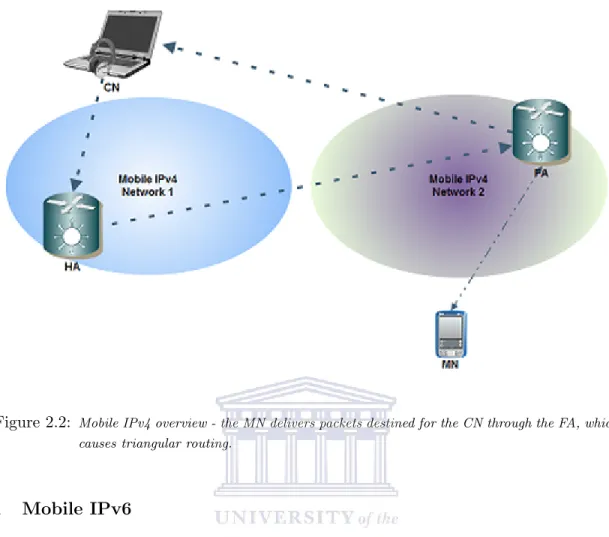
• Configuration is complex in IPv4, thus, addresses are either set up manually or dynamic host configuration protocol (DHCP) is used for a stateful address configuration [29]. Like IPv4, MIPv4 has issues of its own, particularly with real-time multimedia applications [39]. Triangular routing is the main problem in MIPv4 as illustrated in Figure 2.2, where the MN is able to deliver packets destined for the corresponding node (CN) using a path through the foreign agent (FA). The CN delivers packets destined for the MN to the home agent (HA) in the home network and the HA routes them to the MN. This kind of routing is not ideal because the packets from the CN to the MN take the long path by passing through the home network of the MN instead of direct communication between the MN and the CN [39]. A new protocol and standard was needed to address these limitations.
Section 2.1.1 introduces MIPv6 protocol implemented in WLANs. Section 2.1.2 presents the hierarchical extension of MIPv6. Section 2.1.3 introduces another extension of MIPv6 that utilizes the fast handover scheme. Section 2.1.4 discusses the protocol that combines hierarchical scheme of HMIPv6 and fast handover scheme of FMIPv6. Section 2.1.5 introduces a non-standard MIPv6 extension that uses a node calledDecision Engine to observe the MN.
Figure 2.2: Mobile IPv4 overview - the MN delivers packets destined for the CN through the FA, which causes triangular routing.
2.1.1 Mobile IPv6
MIPv6 [39] is intended to deal with MNs in motion between IPv6 networks (see Figure 2.3). When a MN is on the move and connects to a new AR in another subnet, its home address is not valid any longer, therefore it requires a new address in the visiting subnet. The MN obtains a new address called care-of-address (CoA) to register with its HA and the CN whilst the MN is away from home network. The mapping of the home address and CoA of the MN so that the HA can at all times recognize the communication of the MN is calledBinding[30].
In MIPv6, the handover procedure occurs when the MN examines router advertisements sent by the AR or the MN requests the AR to send router advertisements (router solicitation) and realizes that it is no longer in the home network. The CoA is created using information in the router advertisements. Firstly, the MN confirms that the link-local address is unique, then creates the new CoA by auto-configuring a stateful or stateless address. The process of verifying the address is unique is called duplication address detection (DAD) and it involves sending neighbor
Figure 2.3: Mobile IPv6 overview - MIPv6 is able to support seamless mobility more efficiently than MIPv4 because of its robustness, easiness and reliability. MIPv6 also supports route opti-mization which results in effective route creation between the MN and the CN.
solicitation to the new address. DAD takes some time which increases handover latency. To deal with the DAD’s additional time during handover, the MN carries out DAD at the same time of its communications. The MN sends binding updates (BUs) to the HA and the CN when the assembling of CoA is finalized [32].
MIPv6 is able to support seamless mobility more efficiently than MIPv4 because of its robust-ness, easiness and reliability. MIPv6 also supports route optimization which results in effective route creation between the MN and the CN. Nevertheless, sometimes it takes too long to send BUs after handover, which results in packets destined for the MN being dropped [32]. Hierar-chical handover for Mobile IPv6 (HMIPv6) and Fast handover for Mobile IPv6 (FMIPv6) were proposed by Internet engineering task force (IETF) as extensions of MIPv6 to enhance its benefits [15]. HMIPv6 concentrates on localizing the mobility management by minimizing signaling load within a network. FMIPv6 offers anticipated handovers by using Layer 2 triggers to initiate the handover process beforehand [15]. HMIPv6 and FMIPv6 mobility management protocols will
be explained in detail in the following sub-sections. Furthermore, FHMIPv6 and Seamless MIP (SMIP) protocols are introduced later on.
2.1.2 Hierarchical Mobile IPv6
HMIPv6 (RFC 4041) [45] has been proposed by IETF to reduce the amount of signaling load to the CN and the HA by allowing the MN to register in a domain locally (see Figure 2.4). The MN does not require sending BUs to the CN and the HA like in flat MIPv6 [6].
Figure 2.4: HMIPv6 overview - The MN does not require sending BUs to the CN and the HA like in flat MIPv6. The MAP in HMIPv6 provides support for the hierarchical arrangement and manages the binding process for the MN present in its domain.
Mobility anchor point (MAP), a conceptual entity provides support for the hierarchical ar-rangement [6]. MAP is a router that manages the binding process with the MNs present in its domain and it is normally located at the edge of the network. It controls ARs and receives packets destined for the MNs inside its domain. When handover takes place, the MN must register with the new MAP serving that network domain. The MAP serves as a HA for the MN in that it interrupts the packets destined for the MN’s address and tunnels them to the CoA of the MN
in the foreign network. Once the MN changes its CoA in the MAP domain, it registers the new CoA with the MAP; this is labeled local CoA (LCoA) [6]. To communicate with nodes outside the domain, the MN obtains a regional CoA (RCoA), which is the address of the current MAP. The MAP binds the MNs RCoA and the LCoA after the MN sends BUs and the MAP sends back the BAck to the MN notifying the successful registration. Every time the MN changes its RCoA, a binding update is sent to the HA of the MN [45]. The hierarchical arrangement contributes to minimizing the location update signaling since the regularity of the HA registration is reduced. When using HMIPv6, the MN only executes HA registration when it moves to another MAP domain. If the MN moves within the MAP domain, then there is no need for HA registration. This technique helps to minimize the total handover delay by decreasing the HA registration delay [46].
2.1.3 Fast Handover for Mobile IPv6
MIPv6 defines procedures which include movement detection, IP address configuration, and lo-cation update for the MN to retain connectivity during handover. Real-time applilo-cations such as VoIP and video conferencing are affected as a result of the combined handover latency. These real-time applications can benefit from reduction of this latency [30].
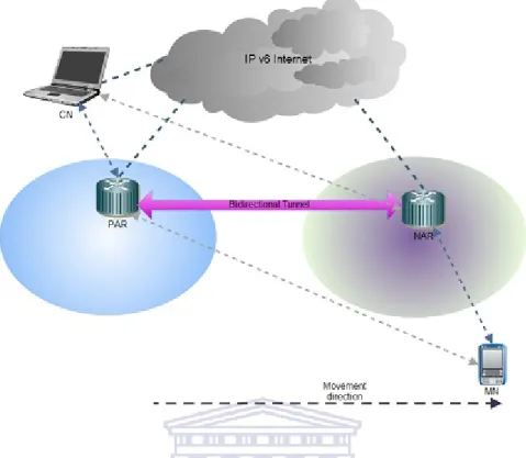
FMIPv6 (RFC 4068) [23] has been proposed as a remedy to reduce the disturbance of com-munication on the MN as it moves from one point of attachment to the other. This mechanism enables the MN to send or receive packets from the period of time it de-associates with one point of attachment in a subnet to the period of time it associates with a new CoA from the new point of attachment in a new subnet. The main objective of FMIPv6 is to leverage information from Layer 2 to either anticipate or promptly react to a handover incident. This permits the MN to associate with the new point of attachment more quickly [32].
FMIPv6 uses bi-direction tunnels (BDT) between the previous access router (pAR) and the new access router (nAR) to transfer data packets during handover (see Figure 2.5). The pAR is the router that the MN is currently connected to, whereas, the nAR is the router that the MN is about to connect to. FMIPv6 technique decreases the handover delay by decreasing the address resolution delay. The new CoA of the MN is pre-configured before the MN connects to the nAR [32].
Figure 2.5: FMIPv6 overview - FMIPv6 uses bi-direction tunnels between the pAR and the nAR to transfer data packets during handover. The pAR is the router that the MN is currently connected to, whereas, the nAR is the router that the MN is about to connect to.
FMIPv6 differentiates between two forms of handover, reactive and anticipated, which are both tunnel-based. A reactive handover denotes a situation where the MN breaks its association with the pAR before it can make an association with the nAR, and it is referred as a break-before-make handover. An anticipated handover denotes to a situation where the MN makes an association with the nAR before it breaks its existing association with the pAR, and it is referred as make-before-break handover. In both situations, whether reactive or anticipated, the MN may configure an IPv6 address in advance before the handover takes place, by utilizing FMIPv6 messaging information [23].
The FMIPv6 messaging (see Figure 2.6) includes;
• Router Solicitation for Proxy (RtSolPr) message, from the MN to the pAR. • the Proxy Router Advertisement (PrRtAdv) message, from the pAR to the MN,
• Handover Initiation (HI) message, from pAR to nAR and
• Handover Acknowledgement (HAck) message, from nAR to pAR.
Furthermore, there are more messages involved such as fast binding update (FBU), fast binding acknowledgement (FBAck) and fast neighbor advertisement (FNA).
Figure 2.6: FMIPv6 messaging enables fast and lossless handovers of the MN from the pAR to the nAR. A fast handover procedure is instigated once the MN sends a router solicitation proxy (Rt-SolPr) message to the pAR after it detects a handover is necessary. The MN also sends the RtSolPr message to the next AR. The pAR responds by sending a proxy router advertisement (PrRtAdv) message to the MN, which holds the information of the nAR whether it is known,
unknown or linked to the same AR. If the nAR is known then the PrRtAdv will contain a network prefix that will be used to create a new CoA. After the new CoA is created using stateless address configuration, the MN sends an FBU to the pAR before the actual handover starts and the pAR or the nAR responds by sending an FBAck to make sure the binding is a success. FNA is sent by the MN if it moves to a new network to trigger the packet forwarding from the nAR [23].
The pAR and the nAR exchange messages between them to enable sending of packets that result in decrease of BU latency. The pAR sends an HI message to the nAR demanding a new CoA registration for the MN and it also holds the previous CoA of the MN. The nAR will then send HAck message to state whether it accepts or rejects the new CoA. If the new CoA is accepted, the pAR sets up a tunnel to the nAR. To create this tunnel, the MN sends a FBU message to its pAR and the pAR starts to tunnel the packets destined for the previous CoA to the new CoA and the tunnel is up until the MN finishes the BU [23].
2.1.4 Fast Handover for Hierarchical Mobile IPv6
Jung et al. [20] proposed combining HMIPv6 and FMIPv6 extensions to MIPv6 (see Figure 2.7). Fast handover for hierarchical mobile IPv6 allows signaling overhead and BU delay during han-dover to be reduced by using HMIPv6 procedures. Furthermore, movement detection latency and new CoA configuration delay during handover are reduced by utilizing FMIPv6 processes. When the MN associates with a new MAP domain, HMIPv6 procedures are performed with the HA and the MAP. If the MN moves from a pAR to a nAR within the domain, it follows the local BU process of FHMIPv6. Packets sent to the MN by the CN during handover are tunneled by the MAP en route for the nAR [20].
FHMIPv6 supports both network-initiated and mobile-initiated handovers. Network-initiated handover involves Layer 2 triggers from the pAR or nAR notifying that the MN is on the move. The following steps are involved in FHMIPv6 procedure [21]:
• The MN sends the RtSolPr message to the MAP, based on Layer 2 handover anticipation. The RtSolPr includes information about the Layer 2 address or identifier of the involved nAR.
• The MAP sends the PrRtAdv message to the MN in response to the RtSolPr message. The
Figure 2.7: FHMIPv6 overview - A handover tunnel is established between the MAP and the nAR, rather than between the pAR and the nAR, and the MN exchanges signaling messages with the MAP, rather than the pAR.
PrRtAdv has information about the Layer 2 address or identifier of the involved nAR. • The MN sends a FBU message containing PLCoA and IP address of the nAR to the MAP. • The MAP sends a HI message to the nAR after receiving the FBU message. A BDT between
the MAP and the nAR is established as a result.
• The MAP sends FBACK messages towards the MN over PLCoA and NLCoA. The MAP
starts sending packets to the nAR destined for the MN by using the tunnel.
• When the MN detects that it is moved in the Layer 2, it sends FNA messages to nAR. Then the nAR delivers the buffered data packets to the MN over the PLCoA.
• The MN then follows the normal HMIPv6 operations.
• Finally, the MAP sends local binding acknowledgement (LBACK) in response to the LBU and the HMIPv6 procedures will be followed again.
2.1.5 Seamless Mobile IPv6
S-MIP was proposed by Hsieh et al. [16]. Even though S-MIP has not been standardized by the IETF, its processes are similar to FHMIPv6 and it is considered as a further extension of FHMIPv6. S-MIP is a seamless handover protocol for hierarchical MIP architectures that enables the reduction of time period the MN fails to send and receive data packets during handover. As a result, communication disruption during Layer 3 handover is reduced. Data packets are delivered to the MN while it is still connected to the pAR. A new node called Decision Engine (see Figure 2.8) is used to observe movements of the MN and decides how to handle the handover [16].
Figure 2.8: S-MIP overview - S-MIP Architecture builds on the fast handover and hierarchical schemes and introduces the use of an intelligent handover mechanism utilizing a decision engine [16].
When handover is initiated, data packets received by the MAP from the CN are replicated and sent to both the pAR and the nAR concurrently and are marked with a Simulcast (Scast) bit in the IP header. A BDT is created between the pAR and the nAR whereas in FHMIPv6 the tunnel is created between the MAP and the nAR [16].
As in HMIPv6, FMIPv6 and FHMIPv6, Layer 3 handovers are initiated by the Layer 2 triggers that can be initiated by the MN or the network. The only difference is the initial messages. Mobile-initiated predictive S-MIP handover procedure activates when a Layer 2 trigger is Mobile-initiated by the MN. It sends the RtSolPr message to pAR, which comprises the information to identify the nAR. Then Handover Initiation- handover acknowledgment (HI-HACK) messages are exchanged between pAR and nAR to initiate a BDT and agree on the MN’s next link CoA (NLCoA). Then the PrRtAdv message containing information about the MN’s NLCoA is sent to the MN by the pAR. The Layer 3 handover is initiated by the MN by sending the FBU message to the pAR. The MAP receives a Simulcast message from the pAR informing the MAP to set theSbit in packets. The pAR sends the FBACK message to NLCoA and previous link CoA (PLCoA) [16].
Table 2.1: Handover performance comparison of IPv6 mobility protocols.
Classification Delay Packet loss rate Signal load
MIPv6 Standard Mobile IP Poor Poor Poor
HMIPv6 Hierarchical management scheme Acceptable Acceptable Good
FMIPv6 Fast switching scheme Good Good Very poor
FHMIPv6 Fast hierarchical management scheme Good Good Good
S-MIP Similar to FHMIPv6 scheme Good Good Good
2.1.6 Related work
After studying the five mobility protocols, it is clear that they all manage the handover in different ways. Table 2.1 compares these protocols qualifying to how they manage delay, packet loss and signaling load during handover. Literature study indicates that handover latency experienced by MIP and its extensions has been studied in numerous publications [10] [13] [15] [24] [50] [55].
Gwon et al. [13] investigated a handover performance of MIP and its extensions (see Table 2.2). The investigation involved simulating 100,000 mobile subscribers across a large scale
exper-
imental network consisting of WLANs. The results indicated that HMIPv6 suffers considerably less handover signaling overhead than FMIPv6. FMIPv6 achieves the best handover performance exhibiting the lowest latency and data loss. FHMIPv6 achieves similar handover performance to that of FMIPv6 but with improved handover signaling overhead. FHMIPv6 is also more robust to AR and HA failures.
Table 2.2: Handover latency presented in [13]. Protocol Handover latency in milliseconds (ms) MIPv6 1300
HMIPv6 300 - 500 FMIPv6 200 FHMIPv6 200 - 400
Hsieh and Seneviratne [15] compare the five IPv6 handover protocols discussed in Section 2.1 (see Table 2.3). The authors use the topology and link delays shown in Figure 2.9.The results show that S-MIP performs best under both ping-pong and linear movement during handover. All other protocols suffer from packet loss and performance degradation. Optimization of S-MIP is proposed to improve its performance. Chow et al. [10] propose a protocol for both macro and micro mobility management in mobile broadband wireless access networks. The mobile-initiated handovers are based on Signal-to-Noise-and-Interference-Ratio (SNIR). The proposed protocol is similar to FHMIPv6, although the terminology used is different, for example, the MAP is replaced by a domain AR. The experiments are conducted in OPNET simulator. The topology used is similar to Figure 2.9 but uses 802.16e standard. In the results, the handover latency is defined as the delay incurred for obtaining a new CoA. It is not the communication between the MN and the CN. The proposed scheme experiences 128 ms delay while obtaining a new CoA.
2.2
Mobility management protocols in Wireless Mesh Networks
A literature review of mobility management protocols in WMNs was conducted and is reported in this section. WMN mobility protocols tend to focus onclient-side transparency, as reported in Section 2.2.1. In addition, other WMN protocols are highlighted briefly concentrating onintra-
Figure 2.9: Topology used in [15] and [10]. Both CN and HA are connected to an intermediate node (N1) with 2ms link delay and 100 Mbps links. The link between N1 and the MAP is a 100 Mbps link with 50 ms link delay. The MAP is further connected to the intermediate nodes N2 and N3 with 2ms link delay over 10 Mbps links. N1 and N2 are connected to PAR and NAR with 2ms link delay over 1 Mbps links.
Table 2.3: Handover latency presented in [15]. Protocol Handover latency in milliseconds (ms) MIPv6 814
HMIPv6 326 FMIPv6 358 FHMIPv6 270 S-MIP 100
domain mobility support in Section 2.2.2 andinter-domain mobility support in Section 2.2.3.
2.2.1 Client-side transparency
Client-side transparency refers to when the MN is unaware of the mesh networking backbone. The MN views the network as one big network and associates with an AP using a traditional association mechanism in WLANs. This sub-section presents the followingclient-side transparency schemes: SMesh [3],iMesh [33] and Ant [51] mobility protocols for WMNs [31].
SMesh [3] is a scheme developed at John Hopkins University by the Distributed System and Networks Lab. SMesh provides seamless mobility and fast handover without the clients pre-installing anything (see Figure 2.10). Any 802.11 mobile device which supports dynamic host configurationl protocol (DHCP) will be able to connect to SMesh network. SMesh is a wireless mesh network that allows unmodified clients to connect and roam freely between access points on a wireless coverage area. The wireless clients perceive the wireless mesh as a single omni-present access point. All nodes have the same service set identification (SSID) using independent basic service set (IBSS) in ad-hoc mode. Some nodes are connected to the Internet (mesh Internet gate-ways). As the client moves, the mesh nodes continuously monitor the mobile client connectivity to decide the best access point that should service the client [3].
SMesh uses a DHCP server to allow mesh routers to rapidly locate and manage mobile client’s connectivity. SMesh client is associated with a client control group (CCG) and a client data group (CDG) which are multicast groups. CCG consists of a group of access points which communicate among each other to determine the best set of access points to serve a client. A CDG consists of a group of access points from CCG which have the best connectivity to the client. For example (see Figure 2.11) IP address of Client A is 10.1.2.3 and its CCG IP address is 224.1.2.3. Each AP calculates the distance to the client and compares the results with other members of the group. APs with the best results form a new CDG multicast group. After extracting IP address from the client, CDG IP address is created, as in this example (see Figure 2.11) 255.1.2.3 is the CDG IP address. Although, handover performance is improved using this multicasting concept, bandwidth use is rapidly increased [3].
iMesh [33] is another WMN architecture used for community networking applications. iMesh uses 802.11b technology for its access mesh routers and aims to provide seamless network services to mobile clients. Like SMesh, client side transparency is an essential objective of the design of
Figure 2.10: SMesh architecture - SMesh is based on Spines messaging system that provide transparent multi-hop unicast, multicast and anycast communication between the mesh nodes. SMesh provides the illusion of a single distributed AP to MNs. This is accomplished by providing connectivity information to mesh clients through DHCP.
this architecture. Mesh clients are not aware of the mesh backbone. Hence they view they whole network as a single AP. When a mesh client is on the move and associates with a different AP (see Figure 2.12), a Layer 2 handover mechanism initiates routing updates in the mesh backbone. The handover procedure involves both Layer 2 and Layer 3 mechanisms. When implementing iMesh, [33] used two solutions: transparent mobile IP, which is similar to MIP and a flat routing scheme, which according to [33] is much better than a traditional Layer 3 handover technique.
The architecture of iMesh uses 802.11-based APs in infrastructure mode that provides com-plete client-side transparency as opposed to operating in ad hoc mode. This way, the system is able to operate without any specialized software on the MNs. The MNs understand the network is wireless LAN but the APs are connected by the distribution system (DS) that are made of wireless backbone network usually called wireless distribution system (WDS) (see Figure 2.13).
Figure 2.11: SMesh example - Client A communicates with Client B. While Client A is on the move, mesh nodes 3, 4 and 6 receive DHCP request and calculate the power of the request. In this case, mesh node 4 indicates being the nearest, as a result, mesh node 4 joins the multicast data group 225.1.2.3.
WDS links are used to communicate between neighboring APs. The WDS links are configured to the neighboring APs by emitting Layer 2 beacon messages that are eavesdropped by neighbor discovery protocol in infrastructure mode. When a MN moves to another network and associates with a new AP, the association triggers a routing update in the network and data packets destined for the MN are sent to the new AP, which is usually not mobile and is powered by a power outlet. The power outlets enable the researchers to get rid of power optimization issues when designing the mesh network architecture. Proactive routing protocols, which are based on approaches such as link state and distance vector, are used instead of on demand routing approaches associated with mobile ad hoc networks (MANETs). This enables the mesh network to be steady for a long period of time [33].
Ant [51] is a another WMN mobility management scheme which also employs client side transparency like SMesh and iMesh. It creates bi-directional tunnels between previous mesh
Figure 2.12: iMesh overview - When a MN moves to another network and associates with a new AP, the association triggers routing update in the network and data packets destined for the MN are sent to the new AP. This handover process involves both Layer 2 and Layer 3 procedures.
nodes and a new mesh node during handover, similar to fast handoff [RFC 4068] [23]. This scheme is used to reduce handover latency and packet loss. A location server on a neighborhood mesh node is used by the new mesh node to determine the previous mesh nodes IP address. The previous node decreases packet loss by buffering the packets when the media access control (MAC) layer de-association event is triggered [51].
Even thoughSMesh,iMesh andAnt WMN mobility management protocols are implemented differently, they all use a client side transparency scheme. This transparency feature enables mesh nodes to support mobility in any heterogeneous network because the mobility management protocol is not incorporated into a mesh node’s stack. However there will be limitations to the MN trying to roam between a 4G network and these client side transparency networks. This is so because these networks will be using different mobility management mechanisms, which will be difficult to manage. 4G networks will be a combination of wired and wireless networks interworking together. Therefore, mobility management protocols such as MIPv6, HMIPv6 and
Figure 2.13: iMesh architecture - WDS links are used to communicate between neighboring APs. The WDS links are configured to the neighboring APs by emitting Layer 2 beacon messages that are eavesdropped by neighbor discovery protocol in the infrastructure mode.
FMIPv6 will be essential for future seamless mobility in 4G networks [31].
2.2.2 Intra-domain mobility support
Intra-domain [14] handovers occurs when the MN moves within a confined administrative domain. A domain is defined as a set of network resources managed by a single administrative entity that authenticates and authorizes access for the MNs. An administrative entity may be a service provider or an enterprise. Mobility management protocols such as MobileNAT [4], DHCP and ad hoc on demand vector (AODV) [40], and Mobile Party [44] support intra-domain mobility.
MobileNAT [4] is a WMN mobility management protocol that combines NAT procedures with mobility management processes. MobileNAT lets a gateway mesh router NAT all the traffic destined for Internet nodes using the public IP address of the gateway, which is referred to as an anchor node (AN). Each MN associates itself to one mesh router when it first boots up.
Intra-domain mobility enables the MN to roam in the AN’s domain [4].
DHCP and AODV [40] can also be used as a mobility solution similar to MobileNAT. Each MN obtains an IP address dynamically that it retains when it is moving from one mesh router to the other. When a MN associates with a mesh router, the mobility agent (MA) in the mesh router broadcasts corresponding IP address routes in the AODV mesh network. Proactive updates are enabled by the MA in the other mesh routers when the MN is detected or lost. These proactive updates increase the handover performance.
Mobile Party is another WMN mobility management protocol that uses address management for mobility support [40]. In Mobile Party [44], an address tree is used to allocate new addresses for the mesh nodes. These addresses are unique and assigned dynamically after considering the location of the MN in the mesh network. Association of neighboring mesh nodes is determined by the levels of node addresses in the address tree. The new neighbor sends a newly configured address to the MN and it also becomes the new parent of the MN in the address tree. Routing is simplified and the handover delay is reduced by this tree-based address management mechanism [44].
2.2.3 Inter-domain mobility support
Inter-domain [52] handovers occur when the MN changes its point of attachment from one ad-ministrative domain to another adad-ministrative domain. AODV pre-handover route discovery (AODV-PRD) [48], OLSR-FastSync [47] and iMesh [33] are some existing mobility management protocols that support both intra-domain and inter-domain mobility.
AODV-PRD[48] aims to reduce Layer 3 handover latency in WMNs that are using AODV ad hoc routing protocol. Multi-hop routes are created in the handover target subnet just before the actual handover. These routes are created to evade route re-discovery delays after handover has occurred [48].
Unlike AODV-PRD, which focuses on AODV-based WMNs, OLSR-FastSync [47] focuses on WMNs using optimized link state routing (OLSR) protocol. In the OLSR-FastSync scheme, the routes to the MN can be calculated straightaway after a handover occurs by enabling the MN to discover, select and declare multipoint relays in the handover target network quickly. These fixed relays of the handover target network also enable the MN to acquire the network topology and
Table 2.4: WMN mobility management protocols summary [53] Mobility domain Address allocation Address
manage-ment
Routing
MobileNAT Intra Unique IP address in
mesh backbone, public IP address in internet
No address change in-side domain
AODV-Spanning Tree (AODV-ST)
DHCPandAODV Intra Dynamic IP address No addr. change inside domain
AODV-ST and tunnel-ing
Mobile Party Intra Tree-based Address change when
moving
Tree-based
AODV-PRD Intra and Inter Unique IP address Address change when moving
AODV
OLSR-FastSync Intra and Inter Unique IP address Address change when moving
OLSR
iMesh Intra and Inter Unique IP address Address change when
moving
OLSR
SMesh Intra MAC address No address change
in-side domain
Link state
Ant Intra Unique IP address No address change in-side domain
Non-std IP routing
gateway information immediately after the handover [47].
AODV-PRD[48], OLSR-FastSync [47], and Mobile Party[44] schemes depend on MIP to man-age the inter-domain mobility support. These Layer 3 mobility manman-agement schemes for WMNs just manage mobility within an administrative domain and let MIP handle mobility between two different administrative domains [53]. Table 2.4 illustrates a summary of the mobility management protocols in WMN that were discussed in this section.
2.3
Summary
This chapter presented work related to mobility management for both WLANs and WMNs. We examined IPv6 mobility management protocols in WLANs such as MIPv6, HMIPv6, FMIPv6, FHMIPv6 and S-MIP. Mobility management protocols in WMNs were also discussed. These WMN protocols that were discussed focused mainly on client-side transparency, intra-domain and inter-domain mobility support. Client-side transparency schemes such asSMesh,iMesh and
Ant mobility protocols for WMN were presented. This transparency feature enables mesh nodes to support mobility in any heterogeneous network because the mobility management protocol is not incorporated into a mesh node’s stack. However it was noted that there will be issues with the MN trying to roam between a 4G network and these client side transparency networks. This is so because these networks will be incompatible with each other and difficult to manage.
After studying the five mobility protocols for WLANs, it is clear that they all manage the han-dover in a different way. That is why they all have advantages and disadvantages when compared according to how they manage delay, packet loss and signaling load during handover. These pa-rameters are discussed in detail in Section 3.4.1. These traditional mobility management schemes can trigger major performance degradation when directly implemented to WMNs because of the multi-hop feature in WMNs. The traditional mobility management schemes rely on infrastructure networks to guarantee good performance. The next chapter is on this challenge with a research question and describes a method used to answer this question.
Chapter 3
Methods and experimental design
This chapter details the research questions and research method. There are many challenges and research gaps associated with mobility management. Section 3.1 introduces these challenges and gaps. Section 3.2 presents the research question and Section 3.3 discusses the research method used to answer this research question. Section 3.4 presents an experimental design to measure handover performance with two simulations. The first simulation has a vertical handover configuration. The second simulation has a horizontal handover setup. Results from conducting experiments with the two simulation setups are presented in chapter 4.3.1
Gaps and challenges
Mobility management in WMNs has still not been researched thoroughly, although a significant amount of research on Wi-Fi, cellular and mobile ad hoc mobility management has been addressed. Networks such as Wi-Fi and cellular depend on infrastructure-based architecture to manage traffic delivery between a MN and a CN, while ad hoc networks depend on multi-hop routing, route maintenance and recovery. The emphasis of handover in an ad hoc network is discovering a multi-hop route rapidly to make sure packets are delivered through the new path as soon as a link goes down. Traditional mobility management schemes cannot be simply extended for multi-hop ad hoc networks because mobility management protocols for infrastructure-based networks with wireless nodes at the edge rely on the good performance of the infrastructure-based network infrastructure. When the traditional mobility management protocols are applied to WMNs, there is no longer assurance for the good performance of delivering signaling traffic [53].
Traditional mobility management protocols for infrastructure-based networks described in Chapter 2 have drawbacks when implemented in WMN environment. For example:
• Hierarchical trees are created when implementing HMIPv6, which make it difficult in WMN, since the network topology is always changing and it is a challenge placing MAPs during network deployment in this environment. However, non-mesh networks have unchanging fixed links [31].
• The period of time of transferring BUs can be compromised in WMNs as a result of its dynamic characteristic nature. Transferring of BUs to the MAP would vary because of the route changes that would result in degradation of performance of real-time applications such as VoIP and video conferencing during handover [31].
Some other major challenges with WMNs include scalability and security. As the amount of mesh nodes increase in the mesh network, routing overhead also increases. Similarly, as the number of hops increase, the performance of the network degrades significantly. Ad hoc networks also lack rigid security solutions as a result of the WMN topology, which tends to be an unplanned graph where routes change dynamically[1].
3.2
Research questions
This thesis answers the following question:How do mobility management protocols such as MIPv6 and FHMIPv6 behave for handover with mesh networks?
Several performance metrics are available for evaluating handover management. These metrics demonstrate different behaviours of the overall network or the individual nodes. QoS parameters are studied in this experiment to evaluate the performance of the network during handover. QoS is a common concern in wireless access networks because of the convergence of the broadband Internet and mobile communications, which has resulted in the increase in use of applications such as VoIP and video conferencing [28]. These applications require minimum disruption dur-ing communication. The main QoS parameters in handover management are throughput, delay and packet loss. Real-time applications require an acceptable level of these QoS parameters for optimum performance. Below is a brief definition of each metric:
• Throughput is the total amount of data that is transmitted at a certain period of time. Unlike the other QoS parameters, throughput is primarily useful for non-real time applica-tions, although it may be useful for measuring total data traffic for applications that are sensitive to packet loss [25]. For example, if the throughput is 85 Mbit/s in a 100 Mbit/s connection, the channel efficiency is 85%.
• Delay (Latency) is the time period that passes between the last data packet received by the MN through the previous point of attachment and the first data packet received by the MN through the new point of attachment during handover. Latency is important for delay sensitive applications because it can result in interruption or poor quality of communication service if there is too much delay [37].
• Packet loss is defined as the number of data packets dropped during handover. Higher layer data traffic dropped by Layer 2 can be due to consistently failing retransmissions. This statistic reports the number of the higher layer packets that are dropped because the Layer 2 could not receive any ACKs for the retransmissions of those packets or their fragments, and the packets’ short or long retry counts reached the Layer 2’s short retry limit or long retry limit, respectively [37].
Because mobility management is affected by different variables, other sub-questions that will be addressed are:
• How is thoughput affected during handover?
• How much delay occurs during handover?
• How much packet loss is there during handover?
Mobility management in mesh is not a simple extension of MIPv6 to multihop wireless net-works. MIPv6 and its extensions’ performance is based on the good performance of mobility-related and signalling traffic delivery in infrastructure networks. However, when these protocols are applied to mesh, the good performance no longer guaranteed. In mesh, signalling messages go through multiple wireless hops. Hence, this increases delay of signal messages. Also, these protocols are designed with a goal of improving throughput but at a cost of signalling overhead.
These additional signalling messages and mobility management signalling messages compete for limited resources. Even low rate signalling traffic can create a negative impact on mesh networks’ performance.
3.3
Research method
The study is designed as an exploratory initiative seeking to establish how MIPv6 and its exten-sions can be used for WMNs mobility management. The study uses only one research method, quantitative research, which is used to gather information in order to answer the research ques-tions and achieve the research objectives. Section 3.3.1 discusses quantitative research method, while Section 3.3.2 addresses experimental quantitative research.
3.3.1 Quantitative research
Quantitative research is one of the most widely used research methods and it involves analyz-ing objects through numeric representations and statistical analysis. Quantitative research is an empirical research method that uses numbers and quantifiable data. It is typically done by col-lecting statistical data via questionnaires, interviews, surveys and experiments. This statistical data is intended to define views of people or some tendencies or developments in the society [34]. Quantitative research fits in a positivist paradigm, which states that real knowledge is founded on experience of senses and can be acquired by observation and experiment. Positivistic thinkers adopt the French philosopher August Comte’s scientific approach as a means of knowledge genera-tion. The outcome of the research represents characteristics used to describe the total population rather than just part of it. The researchers are able to gather useful information from the data being collected from different sources. Unlike qualitative research, quantitative research usually uses standardized methods that afford greater objectivity and the results are more accurate. Recommended actions are deployed to make sure validity and reliability are in place because quantitative research usually involves few variables and many cases. The research is frequently repetitive because of high level of reliability it possesses and it is relies on deductive methods and theories that are examined in acause effect order [34]. Quantitative research advantages include: • Reliability, thus it is an outstanding way of concluding outcomes and (dis)proving a
hypoth-