Virginia Commonwealth University Virginia Commonwealth University
VCU Scholars Compass
VCU Scholars Compass
Theses and Dissertations Graduate School
2017
A Hierarchical Architectural Framework for Securing Unmanned
A Hierarchical Architectural Framework for Securing Unmanned
Aerial Systems
Aerial Systems
Matthew LeccaditoVirginia Commonwealth University
Follow this and additional works at: https://scholarscompass.vcu.edu/etd
Part of the Robotics Commons, and the VLSI and Circuits, Embedded and Hardware Systems
Commons
© The Author
Downloaded from Downloaded from
https://scholarscompass.vcu.edu/etd/5037
This Dissertation is brought to you for free and open access by the Graduate School at VCU Scholars Compass. It has been accepted for inclusion in Theses and Dissertations by an authorized administrator of VCU Scholars
A Hierarchical Architectural Framework for Securing Unmanned Aerial Systems
A Dissertation submitted in partial fulfillment of the requirements for the degree of Doctor of Philosophy at Virginia Commonwealth University.
By
MATTHEW LECCADITO
Master of Science, Virginia Commonwealth University, 2013
Director: Dr. Robert H. Klenke,
Professor, Department of Electrical & Computer Engineering
Virginia Commonwealth University Richmond, Virginia
Acknowledgement
Firstly, I would like to express my sincere gratitude to my advisor Dr. Robert H. Klenke for the continuous support, patience, motivation, and immense knowledge. I could not have imagined having a better advisor and mentor for my graduate studies. Secondly, I would like to thank Dr. Tim Baker, who has helped me every step of the way through my graduate career. I would not be where I am today without the many hours he devoted to me, whether it be discussing solutions, debugging hardware and software, or teaching me various techniques that would contribute to the skills I possess today.
I would like to thank the members of my advisory committee: Dr. Carl Elks, Dr. Milos Manic, and Dr. Edward L. Boone for their insightful comments and encouragement, and for asking the right questions which helped guide me and keep me on the right path. I would like to thank the Virginia Commonwealth University School of Engineering for supporting and funding my academic research in the UAV lab. I would also like to thank Andy Fabian and Andrew Ward for assisting me in the implementation of my research and the insight they have given me. Finally, I must express my profound gratitude to my friends and family for providing me with unfailing support and continuous encouragement through my years of study and through the process of researching and writing this dissertation. This accomplishment would not have been possible without them. Thank you.
Table of Contents
Acknowledgement ... ii
Table of Contents... iii
LIST OF TABLES ... vi
LIST OF FIGURES ... vii
Abstract A Hierarchical Architectural Framework for Securing Unmanned Aerial Systems ... 1
CHAPTER 1 INTRODUCTION ... 2
CHAPTER 2 BACKGROUND AND RELATED WORK ... 8
2.1 Vulnerabilities of a generic CPS ... 8
2.2 Vulnerabilities of a UAS CPS ... 9
2.3 Mitigations, Countermeasures, and Defense Strategies for a UAS CPS ... 19
2.4 Architectural Schemes for securing a UAS CPS ... 24
CHAPTER 3 HIERARCHICAL MONITOR SYSTEM ARCHITECTURAL PRINCIPLES ... 27
3.1 System Model ... 27
3.2 Partitioning Cyber Attacks on a UAV CPS ... 29
3.3 Embedded vs. External ... 32
3.4 Monitor Architecture ... 33
3.4.1 Centralized Architecture ... 34
3.4.2 Distributed Architecture... 34
3.4.3 Hierarchical Architecture ... 35
3.5 (FPGA) Field Programmable Gate Array Implementation ... 38
CHAPTER 4 HIERARCHICAL EMBEDDED CYBER ATTACK DETECTION SYSTEM (HECAD) ... 40
4.1 Overview ... 40
4.2 HECAD Requirements ... 43
4.3 Hardware Resource Integrity Monitor (HRIM) ... 45
4.3.1 HRIM UART Example ... 48
4.3.2 HRIM Operational Characteristics ... 51
4.4 Information Integrity Monitor (I2M) ... 53
4.4.1 Communications Processing and Control... 56
4.4.2 I2M Operational Characteristics... 58
4.4.3 I2M GPS Sensor Example... 60
4.5 Execution Integrity Monitor (EIM) ... 63
4.5.1 EIM Operational Characteristics ... 65
4.6 Functional Integrity Monitor (FIM) ... 66
4.6.1 Use Case: UAV Surveillance Requirements ... 67
4.6.2 FIM Operational Characteristics ... 73
4.7 WISHBONE Bus ... 73
4.8 Securing HECAD ... 77
4.9 Benefit of HECAD ... 80
4.9.1 Sub-module collaboration and increased information ... 81
4.9.2 Improved Isolation and Location Detection of Faults ... 82
4.9.3 Hardware-Software Boundary Attack Detection ... 84
CHAPTER 5 DEVELOPMENT PLATFORM AND DESIGN TOOLS ... 85
5.1 Field Programmable Gate Array ... 85
5.2 VCU ARIES TINY FCS ... 88
5.3 Xilinx Vivado ... 90
6.1 Hardware / low-level communication protocol monitor ... 91
6.2 Cross-sensor data validation in the FIM... 97
6.3 HECAD subsystem isolation... 101
6.4 HECAD Resource Utilization ... 103
CHAPTER 7 CONCLUSIONS AND FUTURE WORK ... 107
7.1 Future work ... 108
LIST OF TABLES
Table 1 CPS Exploits ... 10
Table 2 GPS Vulnerabilities ... 17
Table 3 GPS Spoofing Counter Attack Methods ... 21
LIST OF FIGURES
Figure 1 High Level Abstraction of a UAS FCS architecture ... 4
Figure 2 CPS Vulnerability Taxonomy ... 8
Figure 3 Set of Cyber Attacks ... 31
Figure 4 Embedded vs. External Monitor ... 33
Figure 5 Centralized Architectural Layout of Security Monitor ... 34
Figure 6 Distributed Architectural Layout of Security Monitor ... 35
Figure 7 Hierarchical Architectural Layout of Security Monitor ... 36
Figure 8 HECAD System Overview... 41
Figure 9 HECAD FCS Detailed Overview ... 44
Figure 10 Hardware Resource Integrity Monitor ... 45
Figure 11 Sensor IP Core ... 46
Figure 12 Pulse Width Modulation IP Core ... 47
Figure 13 UART Byte Example ... 49
Figure 14 UART Overclock Sample Baud Rate Configuration @ 57600 ... 50
Figure 15 UART Overclock Sample Baud Rate Configuration @ 115200 ... 50
Figure 16: I2M Overview ... 54
Figure 17 Information Integrity Monitor ... 55
Figure 18 Communications Processing and Control ... 57
Figure 19 Control Flow graph of GPS module in I2M ... 61
Figure 20 Functional Integrity Monitor ... 67
Figure 21 FIM Requirements Example False Data Injection ... 70
Figure 22 FIM Fault Detection and HECAD change of information flow ... 72
Figure 23 WISHBONE Single Read Cycle [67] ... 74
Figure 24 WISHBONE Shared Bus Architecture ... 75
Figure 26 Hardware Peripheral Attack Example ... 82
Figure 27 Sensor isolation upon HRIM attack detection... 83
Figure 28 Digilent Nexys 4 DDR Development Board ... 87
Figure 29 VCU Aries Tiny Flight Control System... 89
Figure 30 GPS Baud Rate fault injection performed in ModelSim (Zoomed In) ... 92
Figure 31 GPS Baud Rate fault injection performed in ModelSim (Zoomed Out) ... 94
Figure 32 Block diagram of HECAD in normal vs mitigation operation ... 95
Figure 33 Logic analyzer capture of a real-world autopilot GPS baud-rate fault ... 96
Figure 34 FIM readings of GPS and Baro altitude and HRIM XBAR enable signal ... 98
Figure 35 GPS and barometric pressure altitude fault injection attack signal trace ... 99
Figure 36 HECAD block diagram of a GPS fault injection detected in the FIM ... 101
Figure 37 ModelSim signal trace of a subsystem failure ... 102
Figure 38 Block diagram of HECAD subsystem failure ... 103
Abstract
A Hierarchical Architectural Framework for Securing Unmanned Aerial Systems
By Matt Leccadito
A Dissertation submitted in partial fulfillment of the requirements for the degree of Doctor of Philosophy at Virginia Commonwealth University.
Virginia Commonwealth University, 2017. Director: Dr. Robert H. Klenke,
Professor, Department of Electrical & Computer Engineering
Unmanned Aerial Systems (UAS) are becoming more widely used in the new era of evolving technology; increasing performance while decreasing size, weight, and cost. A UAS equipped with a Flight Control System (FCS) that can be used to fly semi- or fully-autonomous is a prime example of a Cyber Physical and Safety Critical system. Current Cyber-Physical defenses against malicious attacks are structured around security standards for best practices involving the development of protocols and the digital software implementation. Thus far, few attempts have been made to embed security into the architecture of the system considering security as a holistic problem. Therefore, a Hierarchical, Embedded, Cyber Attack Detection (HECAD) framework is developed to provide security in a holistic manor, providing resiliency against cyber-attacks as well as introducing strategies for mitigating and dealing with component failures. Traversing the hardware/software barrier, HECAD provides detection of malicious faults at the hardware and software level; verified through the development of an FPGA implementation and tested using a UAS FCS.
CHAPTER 1
INTRODUCTION
Cyber Physical Systems (CPS) play an important role in providing critical services in industries such as: autonomous vehicle systems, energy, health, manufacturing, etc., by integrating computation, physical control, and networking. Most of these systems are not only cyber-physical, but also operate in a safety-critical application where a failure or malfunction could result in damage or even loss of life. An Unmanned Aerial System (UAS) meets the requirements of a CPS and safety-critical system with its dependence on wireless communication, sensors, and algorithms that work synergistically to perform its functionality. Innovation in UAS technology has followed the paradigm of enhancing performance as a main priority, with security as either an afterthought or not considered at all, causing a lack of security against cyber-attacks in most UAS. In the past, UAS were expensive, heavy, and most commonly used by the military, however, cost, size, and weight have decreased drastically, while their capabilities, attributed to technology, have increased substantially. Technological advances are rapidly increasing in unmanned systems and secure solutions must keep-up with the technology to maintain safety and assurance. The increased interest in UAS due to semi and fully autonomous flight has benefited the civilian
and military community and lead to increased efforts to incorporate UASs into industry [1]–
[3]. The shift of control from a human pilot to an automated, computerized autopilot has tremendous advantages; however, the dependence on embedded electronics exposes UASs to new threats of cyber-attacks.
The cyber threats to UASs are becoming more evident and research in the area of securing safety-critical CPSs is increasing [4]. Current research is focused on creating attack assessments and discovering vulnerabilities [5]–[8], but has not significantly addressed detection and prevention of cyber-attacks on UASs, and more specifically the UAS Flight
Control System (FCS). A survey has been conducted on cyber-attack vulnerabilities and defenses for flight control systems in [9], as a preliminary assessment to developing a hardware architecture to detect and prevent attacks on a UAS. Vulnerability assessments
typically focus on wireless and Global Positioning System (GPS) attacks [10]–[18] and less
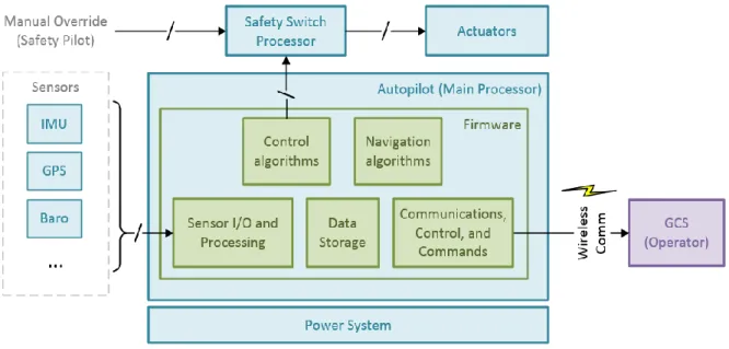
on malicious attacks from within the system. Minimal research has been conducted on increasing resilience of the FCS itself by investigating inter-component communication functionality, detecting sensor data anomalies, and fingerprinting of normal execution behavior. This research presents comprehensive solutions capable of detecting malicious attacks at various levels and parts of the system, such as a cyber-attack in the form of malicious code injected into the onboard sensors and firmware on the FCS with the ability to potentially mitigate the attack and if necessary quarantine the malicious on-board component.. The insight gained from the assessments has been used to develop an architecture to secure a UAS FCS from cyber-attacks. A block diagram of a typical UAS FCS is shown in figure 1 and can be used as a guide to examine the vulnerabilities of the FCS. The FCS consists of an autopilot, which is typically the main processor performing navigation and control algorithms that control the UAS while simultaneously polling sensors, controlling physical actuators and managing command, control and communication with a Ground Control Station (GCS) operator.
The communication links between the FCS and the other on-board sensors are open to vulnerabilities, which can be easily identified: sensors, actuators, and wireless communication. The fourth vulnerability is the firmware running on the main processor, which can consist of not only the navigational and control algorithms, but the lower level driver software. Not only is the code written by an error prone human, but may also need to be updated for various reasons, which is typically performed by the UAS operator who may have little knowledge of the potential security vulnerabilities within the FCS. It is common
for a user to purchase a ready to fly, Commercial Off-The-Shelf (COTS) UAS which does not require any technical understanding of the UAS, creating additional vulnerabilities.
Figure 1 High Level Abstraction of a UAS FCS architecture
The identified vulnerabilities can be divided into four categories: firmware, sensors, communications, and actuators. Many sub-components of a UAS FCS contain embedded firmware vulnerable to attacks through the manufacturing and distribution chain or during run-time by another component having the access and authority to modify or update the sensor firmware.
One of the mechanisms for inserting malicious code onto the autopilot may be through
website spoofing [19]–[21], where an attacker may clone a legitimate website and the user
would download malicious code. Other ways can include a software developer with malicious intent or through maintenance of the autopilot, which would require physical access, where an un-trusted source can program malicious firmware onto the autopilot. Analogous to the autopilot main processor firmware is the sensor firmware. The sensor firmware may be corrupted through the manufacturer, distributor, assembly, or during programming of the autopilot. The malicious firmware can affect the communication
between the sensor and autopilot at the protocol level or interfere with the sensor information through false data injection. A sensor may rely on an external reference, where an attacker could possibly spoof the external reference, providing false readings.
The communications network is typically a wireless connection between the autopilot and a GCS operator. The autopilot communicates through a modem on-board periodically transmitting the status of the UAS and receiving configuration and control parameters as well as commands. An attacker within distance of the wireless transmission and with certain knowledge of the signal can receive and transmit data to the modem. The attacker can scan for activity on a specific frequency, or can jam all frequencies through transmitting noise, using up all the available the bandwidth, rendering the autopilot and/or GCS incapable of receiving any legitimate data. If an attacker has knowledge of the wireless protocol as well, they may have the ability to sniff the data communication and perform a man-in-the-middle attack by intercepting and re-transmitting the data, or a replay attack through recording a message and transmitting it later. The attacker can use fuzzing techniques, by sending random data to the modem and waiting for a physical response of the vehicle. If they have knowledge of the command and control, it is possible to send commands and/or control parameters to cause harm or take control of the vehicle.
The actuators are also vulnerable to attacks, which depending on the capabilities of the actuator, it may contain firmware or can be modified through physical manipulation. It is also possible to attack the actuators through the autopilot or the network, which may require modification of the autopilot firmware or parameters that may be configurable through the network. The UAS FCS has various parts that can be targets for cyber-attacks such as the main processor executing the autopilot firmware, on-board components and sensor firmware, wireless network, and ground control station. There currently does not exist any solution capable of monitoring the on-board components, integrated on the FCS, that
connects between the main processor and on-board components allowing the ability to monitor on-board functionality.
Objectives of the Dissertation
The objective of this dissertation is to present the design, development, and testing of an FPGA implementation of the hierarchical architecture accompanied by a set of detection algorithms that can be integrated into a UAS FCS (an example of a CPS) to monitor, detect, and react against cyber-attacks.
A hierarchical architecture was developed to secure a UAS FCS from malicious attacks at all levels of integration without compromising performance and functionality of the system while in a normal monitoring state through passively sniffing the on-board signals. As is the case of many CPS applications, there are significant size, weight, and power limitations. Furthermore, the monitoring and detection system is designed so that it does not create additional vulnerabilities for the UAS FCS. It performs in real-time and is embedded into the system such that it has the capability to monitor all communication and components within the system and have the ability to isolate any compromised subsystem from the main processor.
Contributions of the Dissertation
To achieve the objectives outlined above, two primary contributions are presented in this dissertation.
The first contribution is a novel methodology that monitors a UAS FCS through monitoring the physical signals between the main processor and on-board components, performing multi-level verification on the systems specification characteristics, dynamic runtime attributes, and system level, functional parameter assertions. In addition, the
methodology allows the ability to use the multi-level verification collaboratively to develop a more concise decision to reduce the amount of false positive attack detections.
Second, the detailed design of the embedded cyber security monitor and detection hardware architecture is presented. It is designed to be integrated directly within the FCS architecture, on-board the PCB and does not require hardware and software external to the FCS. The presented architecture not only allows monitoring of external communication but allows monitoring at all the functional levels of the CPS including hardware level communication protocols, sensor data integrity, and firmware verification. Furthermore, the presented architecture is positioned between the autopilot main processor and on-board sensors and actuators, allowing isolation of compromised components.
CHAPTER 2
BACKGROUND AND RELATED WORK
2.1 Vulnerabilities of a generic CPS
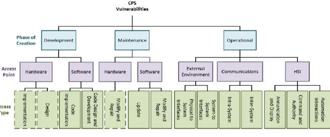
A vulnerability can be defined as a weakness or flaw in the system which an exploit can take advantage of to perform malicious activity. The vulnerabilities of a CPS can vary depending on the application. To characterize the vulnerabilities that exist in a CPS, a taxonomy of vulnerabilities was developed as shown in Figure 2. Although it is not a complete taxonomy listing all vulnerabilities in a CPS, it can be generalized to apply to most systems. The taxonomy does not differentiate between deliberately and non-deliberately created vulnerabilities, as it demonstrates where a vulnerability is created in a general manner. Who created the vulnerability and for what purpose can be considered irrelevant for the purposes of this work.
Figure 2 CPS Vulnerability Taxonomy
The taxonomy shows where the vulnerability lies in the various steps of the life cycle of a CPS. There are three levels of the taxonomy: Phase of Creation, Access Point, and Access Type. The three phases of creation describe where a vulnerability may be developed:
development, maintenance, and operation. The development phase is where the system is initially designed and implemented by the development team which can have access to many parts of the system a typical user would not have access to. This can also be a reoccurring phase depending on the application where a system may continuously be in development. The maintenance phase consists of system upgrades or updates, or any additional modifications to the system which can be carried out by a technician or the user. Vulnerabilities can be induced by the software developer or engineer providing the update to the software or modifications to the system. Lastly, the operational phase refers to vulnerabilities introduced during the operation of the system, such as a communications link that transmits and receives when the system is up and running or external factors that can only be introduced during operation. Vulnerabilities may exist during the operational phase; however, the taxonomy encapsulates the creation of vulnerabilities, not when the vulnerability is exposed.
The access points describe where a malicious attacker would exploit the vulnerability, such as through hardware by modifying the physical components, or software through exploiting a programming bug or inserting malicious code, or eavesdropping on a wireless communication. At the bottom of the taxonomy lies the access types which describes more specifically the type of access a malicious adversary would perform to exploit the vulnerability, e.g. inserting an intentional bug into the code during the development stage, updating the autopilot with corrupt firmware code, or replacing physical components on the FCS.
2.2 Vulnerabilities of a UAS CPS
An assessment on CPS exploits performed in [22] aided in the development of the following list of exploits for a UAS Cyber Physical System. The exploits can be placed into four main
categories: Network, Firmware, Sensor, and Ground Control Station. The first series of exploits consist of network attacks. A network attack can include any type of wired or wireless communications attack. Second are firmware attacks, which are related to the exploits on the software/firmware executing of the main processor of the system. Third are the sensor attacks which refer to the firmware on the physical sensor, external reference manipulation, and any on-board component such as the actuators. Last, are the Ground Control Station (GCS) attacks which are performed on the computer and/or software the operator uses to control and communicate with the UAS. A list of possible exploits are shown in detail in Table 1.
Table 1 CPS Exploits
Method Description
Network Attacks
Black Hole/Gray Hole Compromising the network, dropping all packets (black hole) or selectively dropping packets (gray hole).
Command Injection Accessing a target control unit or network to execute a command with malicious intent.
Communication Jamming Intentional physical interference with the reception of a required signal; the adversary needs to be in vicinity of nodes to use a strong enough signal to jam the wireless channel
Denial of Service Cyber equivalent of jamming; bombarding a network with large volumes of meaningless traffic.
False Data Injection Communication-Based: Compromising the communication channel, blocking data measurements and inserting false data [23]
Fuzzing Gaining network access and bombarding the target with messages to observe which one has a physical effect.
Man-in-the-Middle Connecting independently to two computers that are part of the system with the purpose of eavesdropping and injecting manipulated messages [5], [24].
Network Isolation Attacks aimed at isolating a particular physical geographical area from a network [25].
Packet Sniffing Gaining network access to eavesdrop on messages.
Password Cracking Guessing or otherwise determining a password in documentation or brute force attack.
Relay Attack Capturing a communications signal and relaying it through a longer-range communication.
Replay attack Observing and recording a communication sequence to replay it later in order to spoof the system [7], [11], [14], [17], [26].
Rogue Node Introducing a rogue communications node disguised as a legitimate node.
Code Injection Introducing additional instructions with malicious intent (i.e. Sensor Parsing, Control Algorithm Adjustment, Memory Leaks, and SQL injection).
False Data Injection: Exploiting database vulnerabilities, typically by adding erroneous data [27], [28]. Firmware Modification Modifying a subsystems firmware (i.e. router) to get to the ultimate target [29],
[30]. Requires acquiring samples of an official firmware update, then analyzing, disassembling, and attempting to infer the method used by the device to validate updates.
Sleep Deprivation Causing the system to rapidly exhaust its battery by forcing it to never sleep.
Sensor Attacks
Supply Chain Attack Gaining access to supplier computers and modifying the firmware, e.g., pre-installing back doors, malicious code, etc.
False Data Injection: Sensor-based
Compromising a computer controlled sensor by reporting false data collected by the sensor instead of the actual data.
GPS Jamming Transmitting high power signals to impede reception of GPS signal (i.e., impacting GPS availability).
GPS Spoofing/Meaconing Synthesizing and transmitting a false GPS signal to deceive a target GPS receiver’s location; Meaconing refers to capturing legitimate GPS signal and rebroadcasting with a delay, affecting the timing estimation and ultimately the GPS receiver’s location
Malware Infection Inserting software into the system with deliberate harmful intent
GCS Attacks
Malware Infection Inserting software into the system with deliberate harmful intent [8], [31]. Viruses Parasitic programs that infect other programs, activated when the program is
executed by the user.
Worms Self-replicating programs that do not require human interaction. Back Doors Program that allows unauthorized access to the system.
Bots Program that launches flooding or denial of service attacks.
Root kits Sets of software tools used to conceal the presence of an adversary who has already gained access.
Trojan Horses Software that appears to be useful, but is harmful with malicious code. Key loggers Program that records key strokes on computers where they are installed.
Traditionally, UAS flight control system (i.e., autopilot) software and hardware developers are not fully aware of CPS cyber security vulnerabilities. Cyber threat analysis is typically conducted at a higher level, separate from the design process, by experts in the field. However, conventional cyber security techniques need to evolve from the paradigm of build it, then secure it, to a more concurrent design approach. It is necessary to not only assess the UAS from a high-level system view, but also from a low-level hardware perspective using a more detailed holistic approach. The objective of a cyber-attack on a UAS can be categorized as one of two types: Mission Envelope Failure or Flight Envelope Failure. Mission Envelope Failure is defined as restrictions placed on the vehicle by a cyber-attack (i.e. altitude limits,
GPS boundaries, etc.) that result in failure to successfully complete the UASs mission. Flight Envelope Failure refers to a failure of the flight control system to maintain the vehicles state within the acceptable operating envelope, resulting in failure of the vehicles air-frame and often vehicle destruction.
Network Attacks
UASs typically use wireless communications links for command, control, and communications (C3). The C3 link allows a GCS operator to send navigational commands to change the vehicles flight path, altitude, airspeed, etc. as well as receiving system status and health information from the vehicle. The data communications link, if applicable, allows the real-time transmission of data gathered by the vehicle (e.g. video) to be sent to the operator or other entities. Usually, the data communications link does not affect the operation of the vehicle meaning that it is not safety-critical, although interrupting it may effectively cause a Mission Envelope Failure.
Small, low-cost, COTS UASs were not historically designed with the consideration that the wireless communication channel would be a vulnerability since they were considered to be used as a hobby. It has become evident, however, that the vulnerabilities in UAS communication links can be exploited. With UASs becoming more popular, the use of new, low cost, small, lightweight, and fast encryption capabilities will reduce the probability of wireless security problems. Techniques for securing the wireless communication link in UASs are presented in [10], [17]. In addition, an assessment of different wireless communication channels and sensor attack analysis is performed in [7]; In UAS communication, there are four basic communication architectures [14]: Direct Link/Ad-hoc, Satellite, Cellular, and Mesh Networking. Direct link refers to a connection that is reliable with low latency and little to no interference, satellite communication improves coverage, however has limited bandwidth; cellular refers to using downlink towers that can be
extended for better coverage; and a mesh architecture treats each node as a relay in the system.
Two types of wireless communication for UASs exist, line-of-sight (LOS) and indirect. Indirect communication typically refers to satellite communication (SATCOM). The most common frequency bands used for wireless communication in Unmanned Systems are 400
MHz, 900MHz, 15.15GHz – 15.35GHz, 4GHz – 8GHz, 2.4 GHz and 5.8GHz. The 400MHz band
is commonly used throughout Europe and the rest of the world (excluding US); lower power required, lower path loss than 900MHz, translating to less power for the same range. However, with the lower frequency channel bandwidths can be limited to 10kbits/s or less. The 900MHz Band is commonly used for UASs for narrow band lower data rate applications than the 2.4GHz 5.8GHz band. The 900 MHz Band offers better performance than 2.4GHz or higher bands when obstructions such as trees and water are present. It is often used in non-line-of-sight applications [26]. The 15.15GHz - 15.35GHz up link and 14.40 - 14.85 down link is referred to as the TCDL Ku-Band; a secured link developed by military and susceptible to interference, and can be affected by rain/snow, and air humidity. The 4GHz - 8GHz range is referred to as the C-Band. The UAS range is typically 4.4GHz-4.94GHz and 5.25GHz - 5.75GHz, which are less susceptible to air humidity, but subject to interference by many COTS devices. The most commonly used band is Wi-Fi a/b/g/n: 2.4GHz - 2.48GHz and 5.15GHz - 5.75GHz; which uses MIMO and up to 4 antennas. Omnidirectional antennas have an antenna pattern that radiates in all directions perform better outdoors, however, there is an increased risk of eavesdropping due to its increased radius and the unlicensed commercial nature of the 2.4 and 5.8 GHz bands.
A UAS has three main security breaches associated with its control and telemetry wireless data link [11]: packet forwarding, eavesdropping, and hijacking. Packet forwarding is a technique where the data packets are delivered in an irregular way such as dropping of packets, duplication, or modification. Eavesdropping refers to an adversary silently listening
to the communication, and hijacking is when an adversary gains control of the vehicle through mimicking the GCS.
A typical UAS-GCS communication can be classified as a Mobile ADHOC Network (MANET) like a wireless sensor network (WSN). A WSN typically has static nodes and a MANET consists of dynamic nodes. They pose many of the same vulnerabilities, however certain attacks, such as proximity based attacks (i.e. jamming), would be less effective because the attacker must be mobile. To understand how a UAS may be vulnerable to wireless attacks, WSNs vulnerabilities are investigated. The major attacks on a wireless network can be categorized as follows:
• Denial of Service (DoS)
o Physical Layer: Jamming, tampering
o Link Layer: Collision exhaustion, unfairness
o Network Layer: Neglect and greed, homing, misdirection, black holes
o Transport Layer: Flooding, de-synchronization
• Attack on Information in Transit: Information may be spoofed, replayed, or vanished. • Sybil: Forging an identity; in cases where more than one UAS work together to accomplish a task, an adversary node can pretend to be a peer node or a member of a group when it is not. This can in turn degrade the integrity of data, security and resource utilization, routing, voting, and resource allocation system functions.
• Black Hole/Sinkhole Wireless Attack: Attacker listens to network and finds the highest quality or shortest path between the GCS and a UAS, then attracts all traffic between the two entities and corrupts or destroys it.
• Hello Flood Wireless Attack: In a group of UASs, an adversary sends a Hello type message to initiate friendly contact with a neighboring node, the neighboring node acknowledges this as a friendly node and sends messages through the adversary to
the ground station; typically used in large areas where a mesh type network is utilized.
• Wormhole Wireless Attack: Tunneling or retransmitting data that does not require compromising the network; attacker gives a node a false pretense that the recipient of a message is only one hop away, when it is multi-hops away.
• Botnets: The term botnet refers to insertion of a compromised computer into a network.
UASs can be small, cheap, and easily equipped with wireless networking capability, providing a platform to create a wireless botnet in the skies [32]. Instead of using a fixed computer, attackers can send commands through the non-stationary UAS making it difficult to track the attacker. It is possible to get directly between the GCS and the vehicle in the air, creating a new type of intrusion. Using this method, it is possible to get close enough to attack the wireless network functionality. They can be used to attack a Wi-Fi network by exploiting vulnerabilities in Wi-Fi as well as 3G and GSM [33], acting as an antenna that cell phones would connect through to make calls. UASs can be used to survey a wireless network and gather data such as BSSID, SSID, encryption type, channel, or the MAC addresses of the communicating entities.
Soon, the Automatic Dependent Surveillance Broadcast (ADS-B) will be a major cornerstone of aircraft de-confliction in the National Airspace System (NAS). ADS-B is the next generation of air traffic modernization. It transmits information about the aircraft’s state (i.e. altitude and airspeed) and positional data to other aircraft and ground stations in the vicinity [29]. Two types of corruption of the ADS-B message have been identified, message misuse which is caused by an adversary identifying, locating, and tracking the entity, and message delay, caused by jamming. The ADS-B system will introduce another attack surface into the UAS ecosystem. A white paper released in 2012 by Eurecom referenced in [30], that presented techniques to address the vulnerabilities in the ADS-B
system which include: message authentication to protect from unauthorized users, message signatures to protect from tampering of messages, encryption to protect sensitive data, message integrity to assure validity of the message, and message freshness to protect against replay attacks.
Firmware Attacks
The autopilot contains control and navigational algorithms that are executing in software on the main processor along with low level drivers to communicate with on-board sensors. A firmware attack may include modifying the source code that is executing on the autopilot, which can be inserted during development or maintenance of the UAS. During development of the autopilot software a vulnerability may be inserted intentionally or unintentionally by either a malicious developer or an inexperienced programmer. It is also possible for an adversary to mirror a website that is hosting the source code for the autopilot code, and malicious code can be programmed onto the autopilot by the operator unintentionally.
Sensor Attacks
The sensors on board a UAS include an Inertial Measurement Unit (IMU), absolute and differential pressure sensors, and optical and sonar sensors. Software attacks can occur from insertion of malicious code into the sensor firmware which can then create, modify, or stop data from being sent to the main processor. Software attacks also include, fuzzing attacks that induce noise into the sensor. Unexpected, invalid, completely random noise added to the sensor data flowing into the processor can cause unexpected problems, aircraft instability, process lock-up, and invalid outputs to next process. Digital update rate attacks can delay the frequency of sensor output, causing inconsistent processing of sensor information. Software and hardware can be used to create longer sampling periods to increase the
probability of aliasing. They can also be used to change sampling times of analog-to-digital converters through buffer overflow or hardware manipulation. Denial of service is a threat as well, which can prevent the processor from running at desired update rate. With physical access to the autopilot, malicious hardware can also be inserted between components directly onto the autopilot and/or sensors can be replaced with corrupt sensors to disturb the operations of the autopilot. GPS attacks are the most common types of attacks, since a typical GPS receiver does not use any type of encryption and can be spoofed with little knowledge of the UAS. The most common types of GPS attacks [5] are shown in Table 2.
Table 2 GPS Vulnerabilities
Method Description
GPS Attacks The GPS is an external reference providing position data for the UAS. A GPS receiver can be attacked through manipulation of signal, software, or data [7]. GPS Data Level Attack Manipulation of real-time data with a valid GPS signal, such as resetting the
current year of the GPS receiver to the year of UNIX epoch rollover.
GPS Receiver Software Attack Exploitation of OS vulnerabilities, and in some cases a network stack on high end devices. A GPS receiver is a device and can easily go unpatched against certain attacks.
Reference Station Attack Attacking a reference station that maintains a static position and allows civilian GPS to calculate position with greater accuracy, can be spoofed by
re-transmitting faulty data to dependent GPS receivers.
Spoofing Attacker generates a counterfeit signal with incorrect positional and timing data [8], [9]. GPS spoofing is a proximity based attack and was successfully demonstrated at 0.62km at the University of Texas [10]. An additional limitation to this type is the need to track all GPS signals known to the target UAS.
Signal Delay Using a GPS receiver, the GPS signal is decoded and re-broadcasted creating a timing delay, ultimately generating incorrect positional data; it is only possible to achieve gradual error with this method [11], however, a delay attack can be achieved on military GPS receivers [12].
Jamming An attacker transmits significant RF noise through which the GPS signal cannot be deciphered.
Ground Control Station Attacks
The GCS is used by the operator to send commands, navigate, monitor, and in some cases manually control the UAS. Sometimes it is the only link to the UAS during a mission. Not only is wireless communication between the GCS and the UAS a vulnerability, but the GCS itself can be exploited. Thus, the GCS computer must be independently secured before it is connected to the UAS. The GCS can be a desktop or laptop computer with a keyboard, and consequently a key-logging virus can be inserted that results in the loss of sensitive data or compromising the UAS [31]. An attack may not necessarily occur between the UAS and GCS directly, but indirectly through a separate network that the GCS connects to that ultimately can be used to access the UAS communication link.
As smart device technology increases, the robustness and usability also increases. Desktop computers in the field are becoming antiquated as they are replaced by laptops and mobile devices. With this paradigm shift comes a new level of cyber vulnerability. Not only do most smart devices have more versatile network connection capabilities, but most software development occurs on open source software and third-party applications. A threat model has been developed assessing the vulnerabilities that exist in smart device ground control stations [8]. It shows that smart devices operating systems and software must be updated frequently, along with use of anti-virus software, as they can easily be manipulated to monitor soldiers’ communication and movement. A recursive parameter estimation algorithm was developed in [34] to perform anomaly detection during flight. It can detect cyber-attacks on electronic hardware and the resulting degradation and failure. Adapting the Recursive Least Squares method, it can detect significant changes compared to previously known parameters and alert the GCS operator of an attack.
2.3 Mitigations, Countermeasures, and Defense Strategies for a UAS CPS
A UAS has a more restrictive set of requirements for features such as size, weight, energy usage, and computational power imposed by its physical limitations than a typical CPS, such as a control system for a nuclear power plant or even a ground-based autonomous vehicle. This can make it more difficult to incorporate traditional counter measures that can be applied to other types of CPS. Cyber security techniques for embedded systems related to UASs and other unmanned systems will be discussed in the following section.
Current autonomous vehicle systems that employ some type of detection and protection from cyber-attacks incorporate the following characteristics [32]:
• Multi-Agent System Architecture – Multiple systems composed of subsystems,
creating a system of systems
• Redundancy - Prevents a single point of failure
• Diversity - Prevents a single attack vector from becoming effective
• Defense-in-Depth - Blocks the pathway for an unauthorized user, providing multiple
layers of security countermeasures throughout the system; defending the system from any attack using multiple independent methods
• Authentication - Prevents humans and other devices from impersonating another
entity
• Micro-Kernel - Uses a minimum-sized OS kernel. All unused device drivers and other
software are removed, only the required micro kernel is running
A platform to increase safety and security for unmanned systems known as Sphere was developed in [35]. The purpose of Sphere is to create component usage policies by categorizing modules by different levels of criticality to mission success. A catastrophic effect could result from the failure of a critical component such as the autopilot processor, GPS, or airspeed sensor. Furthermore, the components must be isolated and disabled upon failure.
Secondly, Sphere created a protocol structure for proof of authenticity among the different subsystems, which must authenticate themselves upon start up.
Fault handling is the process of attempting to correct or work around an error in the system once it is detected. It is difficult to assess usefulness of fault handling mechanisms; most common techniques include triple redundancy and fail-safe states. Although these mechanisms cause restrictions on the size, weight, and power of UASs, they help keep the mission alive. It is shown in [7] that fail safe states can impose a risk to the UAS if the wrong state is chosen for a given situation. Fault handling must consider both transient and permanent failures. Transient failures are irregular and un-predictable faults which included external disturbances, while permanent failures typically derive from hardware damage.
ADS-B
As UAS are introduced into the national airspace, it is imperative that the ADS-B system can be as secure as possible from cyber-attacks. Attacks on the availability of ADS-B, such as jamming or denial of service, could be mitigated by employing secure, low frequency, land based alternatives such as terrestrial land based radio navigation systems; a plane to plane type of backup communication could be employed, however another plane could be spoofed [36], allowing a malicious entity to cause further harm. Confidentiality can be augmented using a common group identifier like IP communications and integrity can enhanced through a time-difference-of-arrival technique that helps identify the source of the ADS-B transmission. A lightweight Public Key Infrastructure (PKI) would be a viable solution adding integrity verification to messages [30] through the use of key-hash message authentication (HMAC) to verify message authentication.
GPS Spoofing
Interest in detecting GPS spoofing has increased in the past decade, leading to the development of techniques applied to GPS signal characteristics, including the position solution, Doppler shift, and SNR [37]–[42]. A method is developed in [12] that uses a reference receiver to compare the cross-correlation of the C/A and P(Y) codes. By isolating the P(Y) code, a large correlation can be observed in a non-spoofed signal. A new type of GPS detection was developed using a monopole-patch hybrid antenna connected to two independent GPS receivers that compares the signal to noise ratio to identify a fault [13]. A similar approach for GPS spoof detection was developed in [43] using two or more antennas with known relative positions, and comparing the resulting position solutions as opposed to the RF signal.
There are four main observable ways to spoof a GPS: the GPS message, code ranges, fractional phase ranges and Doppler shift. Various methods that have been developed to counter GPS spoofing attacks [44] are shown in Table 3.
Table 3 GPS Spoofing Counter Attack Methods
Method Description
Monitor the absolute power of each carrier
A maximum power can be set to determine the spoofed signal.
Monitor signal power rate changing
RF signal radiation from a point source. Any positional changes near earth should not result in a dramatic signal power change. magnetic induction
Monitor the relative powers Modern GPS have two signals, the relative power ratios should be fixed.
Bound and compare range rates When phase range is manipulated with respect to code range, phase range rate will most likely be sacrificed and can be detected.
Doppler shift check Relative speed of receiver compared to each satellite can be derived; attacker would need one spoofer per satellite to go undetected. Cross Correlation of L1 and L2 The signal on L2 is slower than that on L1 due to ionosphere effect,
the sign of cross-correlation shift is known.
Residual analysis A GPS signal consists of the spoofed signal, authentic signal, and noise. It is possible to remove the spoofed signal; however, the additional noise may be too strong to recover the weak authentic signal
L1-L2 range differences Range differences are caused by ionosphere effects; phase and code ranges should conform, a spoofed signal propagating in lower levels behaves differently
Verify received ephemeris data Compare spoofed data with almanac data to ensure the GPS message does not provide fixed satellite information
Jump Detection Monitor changes in observables and power consumption are within a tolerable range
Redundancy as well as multi sensor data fusion can be used as a cross-checking mechanism to reduce the risk of integrity or availability loss [45]. A GPS can be combined with an Inertial Navigation System (INS) and an optical sensor [46], which can provide additional information to compare the GPS information against, to reduce the security risk of incorrect position and altitude.
Botnets
A UAS being versatile can be quickly deployed to eavesdrop on a private or corporate
wireless network, and potentially be used as the controlling unit in a botnet. A botnet refers to a large number of computers that are infected with code and controlled by an outside source. A UAS that is performing as a botnet can be difficult to detect, unless there is clear visibility of the UAS being hijacked. A secure defense requires observing the behavior of the UAS and discovering the Geo location of the UAS, or detecting the addition of new hosts in a network that then alert the system to the presence of a botnet.
Low Cost UAS Wireless Encryption
In small UASs, the most widely used wireless modem is the XBEE RF module, more specifically, the XBEE Pro 900HP [47] and the XBEE 802.15.4 [48]. These wireless modules are low power (between 45mA and 215mA), light weight (3g), and small size (2.438cm x 2.761cm). The most common way to secure a wireless network is to add encryption to the data so that it is not decipherable to a casual observer. The addition of encryption, however,
imposes limitations on a wireless network. In an ideal setting, there are unlimited resources available; this is not the case for UASs, especially low-cost hobby and civilian grade UASs. Wireless security in low cost UASs has three main trade-offs: bandwidth, latency, and energy consumption. In a low-cost system, there are greater constraints on the processing capabilities, which limits the usage of encryption algorithms. Less intensive algorithms have been investigated such as Rivest Cipher 4 (RC4), a simple and fast stream cipher, which requires only a small amount of resources and computation.
The XBEE wireless modules have been shown to work with their encryption capabilities enabled for agricultural purposes with low power and cost efficiency [49]. A study was conducted on the performance with and without using encryption on an Arduino UNO Atmega328P processing platform utilizing a Series 1 XBEE wireless module [50]. It was shown that the additional encryption capability of RC4 increased the delay of data transfer from 1ms to 150ms, and the use of RC4 with hash increased the delay from 1ms to 400ms. In [51], wireless vulnerabilities are analyzed between Bluetooth, WIFI, and the XBEE ZigBee wireless modules [52]. The research showed multiple vulnerabilities in the wireless communication, including configuration, non-encryption, and the interface by which the UAS and ground station would connect through, such as a serial port or socket communication. The XBEE wireless module is capable of handling the Advanced Encryption Standard (AES) 128 encryption algorithm on the module itself, which is based on the Rijndael cipher with a block size of 128bits [53]. However, the modules also have enough bandwidth to communicate in typical UAS applications with an AES 256 encryption algorithm performed off-board of the XBEE using an FPGA [54]. The Skipjack algorithm is less resource intensive and just as secure as the RC5 [55] derived from the RC4 algorithm with a few advancements. Applying these less intensive encryption algorithms is a first step into securing the wireless communication links and will prevent most prevalent attacks, however it is also the users’ responsibility to actively enable, monitor, and update security measures. Securing UASs is
only useful if the security measures are actively being used during operation and are shared amongst the user community. For example, it is known that wireless communications are vulnerable to cyber-attack, however, it is not common for COTS UASs to use encrypted communications in civilian applications.
This section has examined the current mitigation techniques, counter measures and defenses for attacks on a UAS CPS and its various subsystems encompassing the hardware, software, wireless communication, GCS, and other potential threats. Many vulnerabilities that lie in a UAS CPS are application specific, however, many of the vulnerabilities can be applied to any CPS.
2.4 Architectural Schemes for securing a UAS CPS
There are currently, two approaches that have been proposed as solutions to securing a low-cost UAV FCS. The first is a System-Aware approach that uses a non-invasive architecture referred to as the Sentinel, and the second uses mathematical modelling and Embedded Domain Specific Language techniques, referred to as HACMS.
The System-Aware Cyber Architecture [56] was developed at the University of Virginia consisting of an integration of diverse, interchangeable, redundant subsystems from multiple vendors. The sub-systems are capable of rapidly changing their configurations and using data consistency checks and a voting scheme to determine a fault versus a natural failure. The system was referred to as the Sentinel, a non-invasive, external system proposed to be capable of monitoring and detecting cyber-attacks on a UAV and has been demonstrated using a Piccolo FCS [57]. The architecture depends on a communication channel between the FCS and the Sentinel. The Piccolo provides a serial communication channel which transmits the information of the autopilot and can also be used to send commands to the Piccolo. The Sentinel architecture polls the information from the autopilot
and performs four different techniques on the data: diversity, configuration hopping, data consistency, and tactical forensics. Implementing diversity requires multiple redundant subsystems from different vendors that perform a voting scheme to monitor and detect any inconsistency in the data. The Sentinel is also capable of changing the autopilot configuration during run-time. Using a voting scheme, data consistency is monitored using redundant subsystems and forensics to rapidly identify the attack, alert the operator, and restore the system. The Sentinel uses a triple redundancy methodology, comprised of three separate Raspberry Pis and a SiCore SHIELD 2 Coprocessor as a central interface point between the autopilot and the Sentinel system.
In most architectural designed systems, horizontal integration is used. This is the concept of developing different subsystems independently and interfacing them to interact together.
A new type of architectural design incorporates vertical integration, using architectural models to ensure compatibility of independent modules within the architecture [37], with the challenge being the trade-off of complexity versus precision of analysis. This approach is built upon using high level models that can develop low level code (i.e. MATLAB Simulink), minimizing the area for error in developing secure code. The vulnerabilities that are embedded in software are typically due to unsafe code written by developers or an unforeseen bug that may appear.
High-Assurance Cyber Military Systems (HACMS) has created an Embedded Domain-Specific Language (EDSL) specifically for embedded systems that is capable of generating safe-C [38]. HACMS was developed by DARPA in an initiative to harden Unmanned Systems from security vulnerabilities. The goal of HACMS is to develop a synthesizer capable of producing a machine-checkable proof that the generated code satisfies functional specifications as well as security and safety policies [36]. It is based on the philosophy of creating a programming language that minimizes all the vulnerabilities in current embedded
system programming languages. HACMS has done a lot of work in CPS with regard to: resilience [40], [41], [58], robustness [59], and attack detection [42].
The current proposed solutions to secure a UAV FCS each have their advantages and disadvantages. The design decision to make the Sentinel a non-invasive system, has the advantage of lower complexities when migrating to another UAV FCS, and does not modify the systems characteristics, and can be easier to maintain. However, in the research conducted in [57] there is a dependency on the existence of a serial communication interface as well as the inability to quarantine and monitor the on-board sensors, verify the firmware, and monitor the run-time execution of the autopilot. The HACMS architecture relies on mathematical proofs and formal verification, as well as an embedded domain specific language to prevent error prone code. However, this approach is very specific and would be difficult to apply to other autopilots, since the entire autopilot would need to be redesigned and recoded. Formal methods may be used to secure the autopilot; however, it can be difficult to detect malicious sensor firmware, communications and actuators attacks by solely incorporating formal methods into the firmware on the autopilot through the use of embedded DSLs.
CHAPTER 3
HIERARCHICAL MONITOR SYSTEM ARCHITECTURAL PRINCIPLES
This section describes the design decisions for the various components and reasons behind the approach of using a hierarchical architecture and subcomponents that make up the proposed methodology. Subsequently, to understand the cyber-attack domain, the system model is defined and followed by a description of what makes an attack detectable or undetectable. Secondly, various architectural methodologies are presented. The following equations will follow a standard model in cyber-physical literature e.g. [60]–[62]. The attacker model is integrated into the system model and consists of attacks on the hardware communication between the sensors and the main processing unit, the firmware on the sensors, the software executing on the main processor, and the actuators that manipulate the control surfaces.
3.1 System Model
Consider the linear control system given by the following equation: 𝑥𝑘+1= 𝐴𝑥𝑘+ 𝐵𝑎𝑘+ 𝑤𝑘
𝑦𝑘= 𝐶𝑥𝑘+ 𝐷𝑎𝑘+ 𝑣𝑘
The system can be defined as = (A, B, C, D) where matrices A and C describe the system and matrices B and D describe the capabilities of the attacker. In the above equation, 𝑥𝑘 ∈ ℝ𝑛
represents the state of the system for k ∈ {1,…,n} ,𝑤𝑘 represents the noise in the system 𝑦𝑘 ∈ ℝ𝑝 represents the measurements from the sensors for k ∈ {1,…,p}, 𝑣𝑘 represents the noise in the measurements, and 𝑎𝑘 ∈ ℝ𝑑 represents the attack injections into the system at time 𝑘 for k ∈ {1,…,d}; ℝ signifies the real numbers set. The system is in normal operating conditions if 𝑘 > 0 and 𝑎𝑘 = 0.
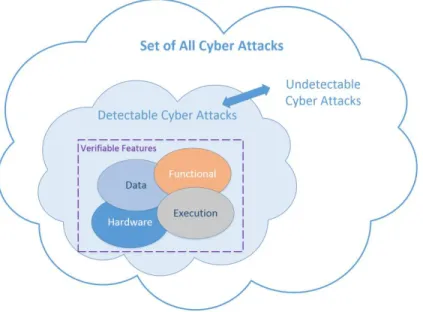
Detectable and Undetectable Cyber Attacks
There exists the set of all attacks, which can be separated into detectable and undetectable attacks. There are three main attributes that must be exhibited for an attack to be detectable. First an attack must be observable, where it must be possible to view the attack. Second, it must be accessible, meaning that there must be some way of retrieving the data, such as using a hardware IP core connected to a physical signal to extract the bits from the communication and parse the data based on the protocol. Lastly, it must be verifiable, meaning that there needs to be something to compare the result against in order to verify that it is correct.
To examine what makes an attack detectable vs. undetectable, we use the following equations derived from [62]. First, we make the assumption that the pair (𝐴, 𝐶) is observable. This model allows for simultaneous attacks on the sensors, main processing unit, and actuators. First we consider the following sequences, first the output sequence:
𝑌𝑘 = [ 𝑦(0)𝑇 𝑦(1)𝑇… 𝑦(𝑘)𝑇 ]𝑇,
and secondly the unknown attack sequence injected by the attacker: 𝐸𝑘 = [ 𝑎(0)𝑇 𝑎(1)𝑇… 𝑎(𝑘)𝑇 ]𝑇,
with k > 0.
As stated previously, the pair (A, C) are observable, and can be used to create the observability matrix: 𝑂𝑘= [ 𝐶 𝐶𝐴 ⋮ 𝐶𝐴𝑇 ],
A detector for a given system , can be defined as:
Where “1” represents that an attack has occurred and “0” represents that no attack has occurred. An attack 𝐸𝑘 is considered undetectable if 𝜕(𝑂𝑘𝛾) = 0 for all 𝛾 ∈ ℝ𝑛 where 𝛾 represents any time step where 𝑎𝑘 ≠ 0. A detectable attack is any attack that is not
undetectable and there exists an occurrence where 𝜕(𝑂𝑘𝛾) = 1. The set of detectable and
undetectable attacks can be combined into the set of all possible attacks ℝ𝑑(𝑘+1). This set of
all cyber-attacks with the detectable vs. undetectable attacks are shown in Figure 3. When developing a monitoring architecture, we must analyze what types of attacks are detectable and undetectable and try to extract as much information as possible from the system.
3.2 Partitioning Cyber Attacks on a UAV CPS
To determine which cyber-attacks against a UAS CPS are detectable and undetectable, we must first define which functions of a UAS are observable:
Function 1 (Sensor communication). The communication between the main processor and the on-board sensors, including the communication between the on-board modem and main processor.
Function 2 (Wireless Communication). The Command, Control, and Communications (C3C) between the Ground Control Station (GCS) and the UAV.
Function 3 (Actuator Outputs). The actuator outputs between the main processor/receiver and the actuators controlling the UAV control surfaces.
Function 4 (Autopilot software). The software programmed onto the autopilots main processor running navigational, and control algorithms as well as hardware peripheral firmware.
Sensor Communication
The communication between the sensors and the main processor can be directly monitored and the attacks on the sensors can be partitioned into various types of attacks. First, a hardware protocol attack, which consists of changing the configuration of the sensors hardware peripheral communication protocol or injecting a fault into the physical signal. Secondly, a firmware attack which is injected by modifying the firmware on the sensor, which can typically occur during a supply chain attack by the manufacturer or distributor. Lastly, a spoofing attack, which requires a sensor to rely on an external reference, where an attacker imitates the external reference with malicious intent.
Wireless Communication
The wireless communication between the UAS and the GCS can easily be eavesdropped on by an adversary within the operating distance of the UAS. The wireless communication operates through a wireless modem which can be monitored onboard the UAV. Attacks may be directed against the wireless communication channel through methods such as Denial of Service (DoS), replay, fuzzing, etc. which mostly are detectable attacks, or indirectly by attacking the GCS and sending command/controls through the wireless channel, which can result in an undetectable attack.
Actuator Outputs
Actuator outputs can be monitored on the FCS directly between the main processor and the actuator. The actuator outputs, depending on the FCS configuration can be driven by either a manual receiver, augmented using a combination of manual and autopilot, or completely by the autopilot in a fully autonomous mode.
Autopilot Software
The autopilot software is programmed into the main processors flash memory, and can be monitored through a debug interface such as JTAG or SWD depending on whether the pins are accessible on the FCS. There are programs available that can make use of formal methods to create statically verified code to minimize error prone code generation.
Information vs. Security Tradeoff
The properties define the observability of the FCS on the UAV and the functionality may contain detectable and undetectable attacks. Figure 3 displays visually how there is a set of all cyber-attacks, where the objective of a cyber-attack monitor is to bridge the gap and minimize the separation of the detectable attacks vs. undetectable attacks.
Figure 3 Set of Cyber Attacks
The objective of a cyber-attack detection monitor is to gather as much information possible to detect an attack. With respect to the monitor obtaining the maximum amount of
information, a trade-off must be made whether the monitor will make a more informed decision and be less secure, or a less informed decision and be a more secure. For example, to detect attacks and/or isolate sensors at the hardware communication level between the sensors and the main processor, it is necessary to create a monitor that passes through or blocks communication between the main processor and the sensor. The capability of blocking communication in the monitor, creates a vulnerability, but it does allow a greater amount of information to be gathered by the monitor to determine that there is an attack ongoing and where it originates. With a greater amount of observability in the system, the amount of detectable errors increases which also allows monitoring at the hardware, data, execution, and functional levels of the system. With a detailed set of observable properties defined, the following sub sections will describe different architectures for creating the best security monitor for cyber-attack detection on a UAV CPS.
3.3 Embedded vs. External
The first decision in developing the proposed methodology is whether the monitor should be an embedded or external isolated system. Embedding the monitor within the system provides a monitor with an increased amount of information, through access to the on-board components that can be used in the fault/attack detection decision making. It allows accessibility of the low-level physical signals that provide internal
communication between the main processor as well as the on-board components such as the actuators and power rails. An embedded approach also allows for the ability to physically isolate a sensor from the main processor and perform a mitigation action. An external system such as the Sentinel discussed in related work, has the advantage that it is a separate system and can be isolated and does not require any modification of the system it is monitoring. However, it is not able to perform analysis of the on-board components
monitoring function at the software level through an external communication line. Because the embedded monitor approach enables the detection of a larger number of cyber attacks and provides the capability to reconfigure the system to mitigate many types of cyber attacks, it was selected as the approach used in this work.
Figure 4 shows the difference between an embedded and an external solution. The embedded version of the monitor is integrated onto the FCS Printed Circuit Board (PCB) as an additional hardware component to connect as a hub between the on-board sensors and the main processor. The external version connects externally through a
communication line that the main processor sends out state information.
Figure 4 Embedded vs. External Monitor
3.4 Monitor Architecture
The selection of an embedded monitor approach leads to the requirement to select the overall architecture of the monitor itself. An embedded monitor can be organized as either a centralized design, a distributed design, or a hierarchical design.
3.4.1 Centralized Architecture
A centralized architecture relies on a single entity that all the subsystems report to determine if an attack has been detected or not. Each subsystem contains its own unique functionality that aids in the overall system fault detection. In this architectural scheme, all the processing within the submodules would be sequential. The advantage of having a centralized architecture would be the sharing of memory and resources, which would allow a great amount of information to be shared between each of the subsystems. The disadvantage would be that everything must flow through the central entity, where if one of the submodules were to fail, the whole system would fail. A layout of the centralized architecture with the various submodules in a security monitor is shown in Figure 5.
Figure 5 Centralized Architectural Layout of Security Monitor
3.4.2 Distributed Architecture
The distributed architecture allows each of the subsystems to work separately from one another and independently report on attacks. Using a distributed architecture alleviates the disadvantage of having a single centralized process deciding on whether an attack has been detected, by allowing each subsystem to alert the target system when an attack has been detected while not disturbing the other sub modules. Also, a distributed architecture allows