Using SiLK for Network
Traffic Analysis
Analyst’s Handbook for SiLK Versions 3.8.3 and Later
October 2014
CERT Coordination Center®
Ron Bandes
Timothy Shimeall
Matt Heckathorn
Sidney Faber
Copyright 2005–2014 Carnegie Mellon University
This material is based upon work funded and supported by Department of Homeland Security under Contract No. FA8721-05-C-0003 with Carnegie Mellon University for the operation of the Software Engineering Institute, a federally funded research and development center sponsored by the United States Department of Defense.
Any opinions, findings and conclusions or recommendations expressed in this material are those of the author(s) and do not necessarily reflect the views of Department of Homeland Security or the United States Department of Defense.
References herein to any specific commercial product, process, or service by trade name, trade mark, manu-facturer, or otherwise, does not necessarily constitute or imply its endorsement, recommendation, or favoring by Carnegie Mellon University or its Software Engineering Institute.
NO WARRANTY. THIS CARNEGIE MELLON UNIVERSITY AND SOFTWARE ENGINEERING IN-STITUTE MATERIAL IS FURNISHED ON AN “AS-IS” BASIS. CARNEGIE MELLON UNIVERSITY MAKES NO WARRANTIES OF ANY KIND, EITHER EXPRESSED OR IMPLIED, AS TO ANY MAT-TER INCLUDING, BUT NOT LIMITED TO, WARRANTY OF FITNESS FOR PURPOSE OR MER-CHANTABILITY, EXCLUSIVITY, OR RESULTS OBTAINED FROM USE OF THE MATERIAL. CAR-NEGIE MELLON UNIVERSITY DOES NOT MAKE ANY WARRANTY OF ANY KIND WITH RE-SPECT TO FREEDOM FROM PATENT, TRADEMARK, OR COPYRIGHT INFRINGEMENT.
This material has been approved for public release and unlimited distribution except as restricted below. Internal use:* Permission to reproduce this material and to prepare derivative works from this material for internal use is granted, provided the copyright and “No Warranty” statements are included with all reproductions and derivative works.
External use:* This material may be reproduced in its entirety, without modification, and freely distributed in written or electronic form without requesting formal permission. Permission is required for any other external and/or commercial use. Requests for permission should be directed to the Software Engineering Institute at [email protected].
* These restrictions do not apply to U.S. government entities.
Carnegie Mellon®, CERT®, CERT Coordination Center® and FloCon® are registered marks of Carnegie
Mellon University. DM-0001832
Adobe is a registered trademark of Adobe Systems Incorporated in the United States and/or other countries. Akamai is a registered trademark of Akamai Technologies, Inc.
Apple and OS X are trademarks of Apple Inc., registered in the U.S. and other countries.
Cisco Systems is a registered trademark of Cisco Systems, Inc. and/or its affiliates in the United States and certain other countries.
DOCSIS is a registered trademark of CableLabs.
FreeBSD is a registered trademark of the FreeBSD Foundation.
iii JABBER is a registered trademark and its use is licensed through the XMPP Standards Foundation. Linux is the registered trademark of Linus Torvalds in the U.S. and other countries.
MaxMind, GeoIP, GeoLite, and related trademarks are the trademarks of MaxMind, Inc.
Microsoft and Windows are registered trademarks of Microsoft Corporation in the United States and/or other countries.
NetFlow is a trademark of Cisco Systems, Inc.
OpenVPN is a registered trademark of OpenVPN Technologies, Inc. Perl is a registered trademark of The Perl Foundation.
Python is a registered trademark of the Python Software Foundation. Snort is a registered trademark of Cisco and/or its affiliates.
Solaris is a registered trademark of Oracle and/or its affiliates in the United States and other countries. UNIX is a registered trademark of The Open Group.
VPNz is a registered trademark of Advanced Network Solutions, Inc. Wireshark is a registered trademark of the Wireshark Foundation. All other trademarks are the property of their respective owners.
Acknowledgements
The authors wish to acknowledge the valuable contributions of all members of the CERT® Network
Situ-ational Awareness group, past and present, to the concept and execution of the SiLK Tool Suite and to this handbook. Many individuals served as contributors, reviewers, and evaluators of the material in this handbook. The following individuals deserve special mention:
• Michael Collins, PhD was responsible for the initial draft of this handbook and for the development of the earliest versions of the SiLK tool suite.
• Mark Thomas, PhD, who transitioned the handbook from Microsoft® Word to LATEX, patiently and
tirelessly answered many technical questions from the authors and shepherded the maturing of the SiLK tool suite.
• Michael Duggan answered frequent questions for the preparation of this handbook, often delving into code and performing experiments to determine the actual working and boundary conditions of SiLK components.
• Andrew Kompanek, who oversaw much of the early transition of SiLK into a more maintainable format, contributed many of the examples in this handbook.
• Marcus Deshon, PhD contributed many examples to this handbook and provided patient guidance to a number of revisions.
• The management of the CERT/CC and the Network Situational Awareness group, in particular Ro-man Danyliw and Richard Friedberg, have provided consistent guidance and support throughout the evolution of this handbook.
The many users of the SiLK tool suite have also contributed immensely to the evolution of the suite and its tools and are acknowledged gratefully.
Lastly, the authors wish to acknowledge their ongoing debt to the memory of Suresh L. Konda, PhD, who lead the initial concept and development of the SiLK tool suite as a means of gaining network situational awareness.
Contents
Acknowledgements v
Handbook Goals 1
1 Networking Primer and Review of UNIX Skills 5
1.1 Understanding TCP/IP Network Traffic . . . 5
1.1.1 TCP/IP Protocol Layers . . . 5
1.1.2 Structure of the IP Header . . . 7
1.1.3 IP Addressing and Routing . . . 7
1.1.4 Major Protocols . . . 10
1.2 Using UNIX to Implement Network Traffic Analysis . . . 14
1.2.1 Using the UNIX Command Line . . . 15
1.2.2 Standard In, Out, and Error . . . 15
1.2.3 Script Control Structures . . . 20
2 The SiLK Flow Repository 21 2.1 What Is Network Flow Data? . . . 21
2.1.1 Structure of a Flow Record . . . 22
2.2 Flow Generation and Collection. . . 22
2.3 Introduction to Flow Collection . . . 24
2.3.1 Where Network Flow Data Are Collected . . . 24
2.3.2 Types of Network Traffic . . . 26
2.3.3 The Collection System and Data Management . . . 26
2.3.4 How Network Flow Data Are Organized . . . 27
3 Essential SiLK Tools 29 3.1 Suite Introduction . . . 29
3.2 Choosing Records withrwfilter . . . 30
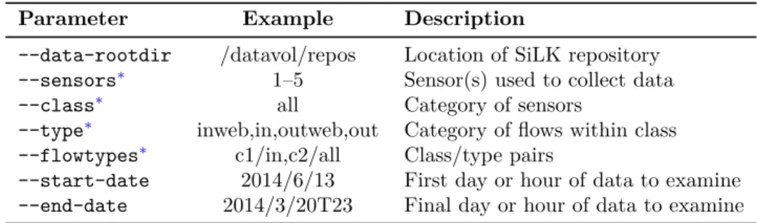
3.2.1 UsingrwfilterParameters to Control Filtering . . . 32
3.2.2 Finding Low-Packet Flows withrwfilter . . . 39
3.2.3 Using IPv6 withrwfilter . . . 40
3.2.4 Using Pipes withrwfilterto Divide Traffic . . . 41
3.2.5 Translating IDS Signatures intorwfilterCalls. . . 41
3.2.6 Using Tuple Files withrwfilterfor Complex Filtering . . . 42
3.3 Describing Flows withrwstats . . . 44
3.3.1 Examining Extremes withrwstatsTop or Bottom-N Mode . . . 44
3.4 Creating Time Series withrwcount. . . 48
3.4.1 Examining Traffic Over a Period of Time . . . 50 vii
3.4.2 Characterizing Traffic by Bytes, Packets, and Flows . . . 50
3.4.3 Changing the Format of Dates to Feed Other Tools. . . 53
3.4.4 Using the--load-schemeParameter for Different Approximations . . . 55
3.5 Displaying Flow Records Usingrwcut . . . 56
3.5.1 Pausing Results with Pagination . . . 56
3.5.2 Selecting Fields to Display. . . 58
3.5.3 Rearranging Fields for Clarity. . . 58
3.5.4 Selecting Fields for Performance . . . 60
3.5.5 Modifying Field Formatting for Clarity . . . 60
3.5.6 Selecting Records to Display . . . 62
3.6 Sorting Flow Records withrwsort . . . 64
3.6.1 Behavioral Analysis withrwsort,rwcut, andrwfilter . . . 64
3.7 Counting Flows withrwuniq . . . 65
3.7.1 Using Thresholds withrwuniq to Profile a Slice of Flows . . . 66
3.7.2 Counting IPv6 Flows. . . 68
3.7.3 Using Compound Keys withrwuniqto Profile Selected Cases . . . 68
3.7.4 Usingrwuniqto Isolate Behavior . . . 69
3.8 Comparingrwstatstorwuniq . . . 69
3.9 Features Common to Several Commands. . . 70
3.9.1 Parameters Common to Several Commands . . . 70
3.9.2 Getting Tool Help . . . 70
3.9.3 Overwriting Output Files . . . 75
3.9.4 IPv6 Address Policy . . . 75
4 Using the Larger SiLK Tool Suite 79 4.1 Manipulating Flow Record Files . . . 79
4.1.1 Combining Flow Record Files withrwcatandrwappend . . . 80
4.1.2 Merging While Removing Duplicate Flow Records withrwdedupe . . . 81
4.1.3 Dividing Flow Record Files withrwsplit . . . 82
4.1.4 Keeping Track of File Characteristics withrwfileinfo . . . 84
4.1.5 Creating Flow Record Files from Text withrwtuc . . . 90
4.2 Analyzing Packet Data withrwptoflowandrwpmatch . . . 93
4.2.1 Creating Flows from Packets Usingrwptoflow . . . 93
4.2.2 Matching Flow Records with Packet Data Usingrwpmatch . . . 95
4.3 Aggregating IP Addresses by Masking withrwnetmask. . . 96
4.4 Summarizing Traffic with IP Sets . . . 97
4.4.1 What Are IP Sets? . . . 97
4.4.2 Creating IP Sets withrwset . . . 97
4.4.3 Reading Sets withrwsetcat . . . 99
4.4.4 Manipulating Sets withrwsettool,rwsetbuild, and rwsetmember. . . 100
4.4.5 Usingrwsettool --intersectto Fine Tune IP Sets . . . 104
4.4.6 Usingrwsettool --unionto Examine IP-Set Growth . . . 104
4.4.7 Backdoor Analysis with IP Sets. . . 104
4.5 Summarizing Traffic with Bags . . . 107
4.5.1 What Are Bags? . . . 107
4.5.2 Usingrwbagto Generate Bags from Network Flow Data . . . 107
4.5.3 Usingrwbagbuildto Generate Bags from IP Sets or Text . . . 108
4.5.4 Reading Bags Usingrwbagcat . . . 111
CONTENTS ix
4.5.6 Using Bags: A Scanning Example . . . 118
4.6 Labeling Flows withrwgroupandrwmatchto Indicate Relationship . . . 119
4.6.1 Labeling Based on Common Attributes withrwgroup . . . 119
4.6.2 Labeling Matched Groups withrwmatch . . . 122
4.7 Adding IP Attributes with Prefix Maps . . . 127
4.7.1 What Are Prefix Maps? . . . 127
4.7.2 Creating a Prefix Map . . . 127
4.7.3 Selecting Flow Records withrwfilterand Prefix Maps . . . 127
4.7.4 Working with Prefix Values Usingrwcut andrwuniq. . . 129
4.7.5 Querying Prefix Map Labels withrwpmaplookup . . . 129
4.8 Gaining More Features with Plug-Ins. . . 133
4.9 Parameters Common to Several Commands . . . 133
5 Using PySiLK for Advanced Analysis 137 5.1 What Is PySiLK?. . . 137
5.2 Extendingrwfilterwith PySiLK . . . 138
5.2.1 Using PySiLK to Incorporate State from Previous Records . . . 139
5.2.2 Using PySiLK withrwfilterin a Distributed or Multiprocessing Environment . . . . 141
5.2.3 Simple PySiLK withrwfilter --python-expr . . . 141
5.2.4 PySiLK with Complex Combinations of Rules. . . 141
5.2.5 Use of Data Structures in Partitioning . . . 142
5.3 Extendingrwcutandrwsortwith PySiLK . . . 144
5.3.1 Computing Values from Multiple Records . . . 144
5.3.2 Computing a Value Based on Multiple Fields in a Record . . . 144
5.4 Defining Key Fields and Aggregate Value Fields forrwuniqandrwstats . . . 147
6 Additional Information on SiLK 151 6.1 Contacting SiLK Support . . . 151
List of Figures
1.1 TCP/IP Protocol Layers . . . 6
1.2 Structure of the IPv4 Header . . . 7
1.3 TCP Header . . . 11
1.4 TCP State Machine . . . 12
1.5 UDP and ICMP Headers. . . 14
2.1 From Packets to Flows . . . 23
2.2 Default Traffic Types for Sensors . . . 25
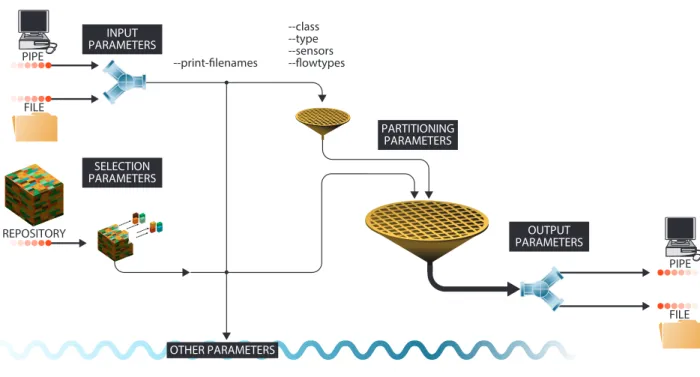
3.1 rwfilterParameter Relationships . . . 31
3.2 rwfilterPartitioning Parameters . . . 33
3.3 A Manifold . . . 38
3.4 Summary of rwstats . . . 46
3.5 Summary of rwcount . . . 50
3.6 DisplayingrwcountOutput Usinggnuplot . . . 51
3.7 ImprovedgnuplotOutput Based on a Larger Bin Size . . . 52
3.8 Comparison of Byte and Record Counts over Time . . . 53
3.9 rwcountLoad-Schemes. . . 55 3.10 Summary of rwcut . . . 56 3.11 Summary of rwsort . . . 64 3.12 Summary of rwuniq . . . 65 4.1 Summary of rwcat . . . 80 4.2 Summary of rwappend . . . 80 4.3 Summary of rwdedupe . . . 82 4.4 Summary of rwsplit . . . 83 4.5 Summary of rwfileinfo . . . 87 4.6 Summary of rwtuc . . . 90 4.7 Summary of rwptoflow . . . 94 4.8 Summary of rwpmatch . . . 95 4.9 Summary of rwnetmask . . . 96 4.10 Summary of rwset . . . 98 4.11 Summary of rwsetcat . . . 99 4.12 Summary of rwsettool . . . 102
4.13 Growth Graph of Cumulative Number of Source IP Addresses by Hour . . . 105
4.14 Summary of rwbag . . . 108
4.15 Summary of rwbagbuild . . . 109
4.16 Summary of rwbagcat . . . 112 xi
4.17 Summary of rwbagtool . . . 115
4.18 Summary of rwgroup . . . 120
4.19 Summary of rwmatch . . . 124
4.20 Summary of rwpmapbuild . . . 128
List of Tables
1.1 IPv4 Reserved Addresses. . . 9
1.2 IPv6 Reserved Addresses. . . 10
1.3 Some Common UNIX Commands. . . 16
3.1 rwfilterSelection Parameters . . . 33
3.2 Single-Integer- or Range-Partitioning Parameters . . . 34
3.3 Multiple-Integer- or Range-Partitioning Parameters. . . 34
3.4 Address-Partitioning Parameters . . . 34
3.5 High/Mask Partitioning Parameters . . . 35
3.6 Time-Partitioning Parameters. . . 35
3.7 Country-Code-Partitioning Parameters . . . 35
3.8 Miscellaneous Partitioning Parameters . . . 35
3.9 rwfilterOutput Parameters . . . 37
3.10 Other Parameters. . . 39
3.11 Arguments for the--fieldsParameter . . . 59
3.12 Output-Filtering Options for rwuniq . . . 65
3.13 Common Parameters in Essential SiLK Tools . . . 71
3.14 Parameters Common to Several Commands . . . 72
3.15 --ip-formatValues . . . 73
3.16 --timestamp-formatValues . . . 73
3.17 --ipv6-policyValues . . . 76
4.1 Fixed-Value Parameters forrwtuc . . . 91
4.2 rwbagbuildKey or Value Options . . . 110
4.3 Current SiLK Plug-Ins . . . 133
4.4 Common Parameters in Advanced SiLK Tools – Part 1. . . 134
4.5 Common Parameters in Advanced SiLK Tools – Part 2. . . 135
List of Examples
1.1 A UNIX Command Prompt . . . 15
1.2 Using Simple UNIX Commands . . . 17
1.3 Output Redirection. . . 17
1.4 Input Redirection. . . 18
1.5 Using a Pipe . . . 18
1.6 Using a Here-Document . . . 19
1.7 Using a Named Pipe . . . 20
2.1 Usingrwsiteinfoto Obtain a List of Sensors. . . 25
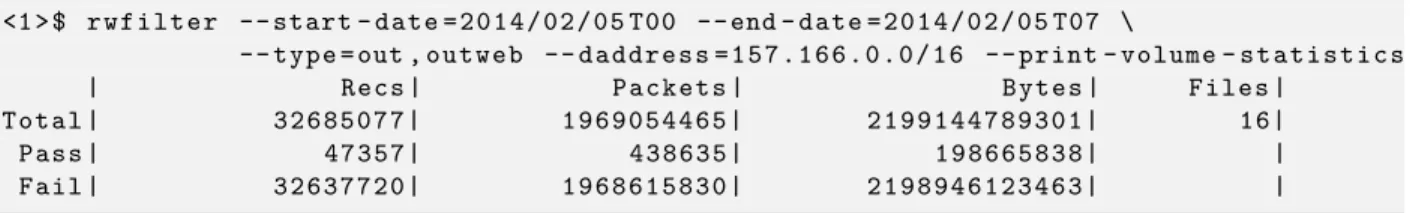
3.1 Usingrwfilterto Count Traffic to an External Network . . . 30
3.2 Usingrwfilterto Extract Low-Packet Flow Records . . . 40
3.3 Usingrwfilterto Partition Flows on IP Version . . . 40
3.4 Usingrwfilterto Detect IPv6 Neighbor Discovery Flows . . . 41
3.5 rwfilter --passand--failto Partition Fast and Slow High-Volume Flows . . . 41
3.6 rwfilterwith a Tuple File . . . 43
3.7 Usingrwstatsto Count Protocols and Ports . . . 45
3.8 rwstats --percentageto Profile Source Ports . . . 47
3.9 rwstats --countto Examine Destination Ports . . . 47
3.10 rwstats --copy-inputand--output-pathto Chain Calls . . . 48
3.11 rwcountfor Counting with Respect to Time Bins. . . 49
3.12 rwcountSending Results to Disk . . . 50
3.13 rwcount --bin-sizeto Better Scope Data for Graphing. . . 50
3.14 rwcountAlternate Date Formats . . . 54
3.15 rwcount --start-timeto Constrain Minimum Date . . . 54
3.16 rwcutfor Displaying the Contents of a File . . . 57
3.17 rwcutUsed withrwfilter . . . 57
3.18 SILK_PAGER with the Empty String to Disable Paging . . . 58
3.19 rwcut --pagerto Disable Paging . . . 58
3.20 rwcut --fieldsto Rearrange Output . . . 58
3.21 rwcutPerformance with Default--fields . . . 60
3.22 rwcut --fieldsto Improve Efficiency . . . 60
3.23 rwcutICMP Type and Code asdPort . . . 61
3.24 rwcutUsing ICMP Type and Code Fields . . . 61
3.25 rwcut --delimitedto Change the Delimiter . . . 62
3.26 rwcut --no-titlesto Suppress Column Headings in Output . . . 62
3.27 rwcut --num-recsto Constrain Output . . . 62
3.28 rwcut --num-recsand Title Line. . . 63
3.29 rwcut --start-rec-numto Select Records to Display . . . 63
3.30 rwcut --start-rec-num,--end-rec-num, and--num-recsCombined . . . 63 xv
3.31 rwuniqfor Counting in Terms of a Single Field . . . 66
3.32 rwuniq --flowsfor Constraining Counts to a Threshold . . . 66
3.33 rwuniq --bytesand--packetswith Minimum Flow Threshold . . . 67
3.34 rwuniq --flowsand--packetsto Constrain Flow and Packet Counts. . . 67
3.35 Using rwuniq to Detect IPv6 PMTU Throttling . . . 68
3.36 rwuniq --fieldsto Count with Respect to Combinations of Fields . . . 68
3.37 Using rwuniq to Isolate Email and Non-Email Behavior . . . 69
3.38 Using --helpand--version . . . 74
3.39 Removing Previous Output . . . 75
3.40 Changing Record Display with --ipv6-policy . . . 77
4.1 rwcatfor Combining Flow Record Files . . . 81
4.2 rwdedupefor Removing Duplicate Records. . . 83
4.3 rwsplitfor Coarse Parallel Execution . . . 85
4.4 rwsplitto Generate Statistics on Flow Record Files . . . 86
4.5 rwfileinfofor Display of Flow Record File Characteristics . . . 86
4.6 rwfileinfofor Showing Command History . . . 88
4.7 rwfileinfofor Sets, Bags, and Prefix Maps. . . 89
4.8 rwtucfor Simple File Cleansing. . . 92
4.9 rwptoflowfor Simple Packet Conversion. . . 94
4.10 rwptoflowandrwpmatchfor Filtering Packets Using an IP Set . . . 95
4.11 rwnetmaskfor Abstracting Source IPv4 addresses. . . 96
4.12 rwsetfor Generating an IP-Set File . . . 97
4.13 rwsetcatto Display IP Sets. . . 99
4.14 rwsetcatOptions for Showing Structure. . . 101
4.15 rwsetbuildfor Generating IP Sets . . . 102
4.16 rwsettoolto Intersect and Difference IP Sets . . . 103
4.17 rwsettoolto Union IP Sets . . . 103
4.18 rwsetmemberto Test for an Address . . . 103
4.19 Using rwsetto Filter for a Set of Scanners . . . 104
4.20 Using rwsettoolandrwsetcatto Track Server Usage . . . 106
4.21 rwsetbuildfor Building an Address Space IP Set . . . 106
4.22 Backdoor Filtering Based on Address Space . . . 107
4.23 rwbagfor Generating Bags . . . 108
4.24 rwbagcatfor Displaying Bags . . . 111
4.25 rwbagcat --mincounter,--maxcounter,--minkey, and--maxkeyto Filter Results . . . 113
4.26 rwbagcat --bin-ipsto Display Unique IP Addresses per Value. . . 113
4.27 rwbagcat --key-format . . . 114
4.28 Using rwbagtool --addto Merge Bags . . . 114
4.29 Using rwbagtoolto Generate Percentages . . . 116
4.30 Using rwbagtool --intersectto Extract a Subnet . . . 117
4.31 rwbagtoolCombining Threshold with Set Intersection . . . 117
4.32 Using rwbagtool --coversetto Produce an IP Set from a Bag. . . 118
4.33 Using rwbagto Filter Out a Set of Scanners . . . 119
4.34 Using rwgroupto Group Flows of a Long Session . . . 121
4.35 Using rwgroup --rec-thresholdto Drop Trivial Groups . . . 121
4.36 Using rwgroup --summarizeto Aggregate Groups . . . 122
4.37 Using rwgroupto Identify Specific Sessions . . . 123
4.38 Problem of Using rwmatchwith Incomplete Relate Values . . . 125
LIST OF EXAMPLES xvii
4.40 rwmatchfor Matching Traceroutes . . . 126
4.41 Using rwpmapbuildto Create a Spyware Pmap File . . . 128
4.42 Using Pmap Parameters withrwfilter . . . 128
4.43 Using rwcutwith Prefix Maps . . . 129
4.44 Using rwsortwith Prefix Maps . . . 129
4.45 Using rwuniq with Prefix Maps . . . 130
4.46 Using rwpmaplookupto Query Addresses and Protocol/Ports . . . 132
4.47 Using rwcutwith--plugin=cutmatch.so . . . 133
5.1 ThreeOrMore.py: Using PySiLK for Memory inrwfilterPartitioning. . . 140
5.2 CallingThreeOrMore.py . . . 141
5.3 Using--python-exprfor Partitioning . . . 141
5.4 vpn.py: Using PySiLK withrwfilterfor Partitioning Alternatives . . . 142
5.5 matchblock.py: Using PySiLK withrwfilterfor Structured Conditions . . . 143
5.6 Callingmatchblock.py . . . 144
5.7 delta.py . . . 145
5.8 Callingdelta.py . . . 145
5.9 payload.py: Using PySiLK for Conditional Fields with rwsortandrwcut . . . 146
5.10 Callingpayload.py . . . 147
5.11 bpp.py. . . 147
Handbook Goals
What This Handbook Covers
This handbook provides a tutorial introduction to network traffic analysis using the System for Internet-Level Knowledge (or SiLK) tool suite. This suite is publicly available athttp://tools.netsa.cert.org/silk/and supports both acquisition and analysis of network flow data. The SiLK tool suite is a highly scalable flow-data capture and analysis system developed by the Network Situational Awareness group (NetSA) at Carnegie Mellon1 University’s Software Engineering Institute (SEI). SiLK tools provide network security analysts
with the means to understand, query, and summarize both recent and historical traffic data represented as network flow records. The SiLK tools provide network security analysts with a relatively complete high-level view of traffic across an enterprise network, subject to placement of sensors.
Analyses Made Possible by SiLK
Analyses using the SiLK tools have lent insight into various aspects of network behavior. Some example applications of this tool suite include (these examples, and others, are explained further in this handbook):
• supporting network forensics (identifying artifacts of intrusions, vulnerability exploits, worm behavior, etc.)
• providing service inventories for large and dynamic networks (on the order of a /8 CIDR2 block)
• generating profiles of network usage (bandwidth consumption) based on protocols and common com-munication patterns
• enabling non-signature-based scan detection and worm detection, for detection of limited-release ma-licious software and for identification of precursors
By providing a common basis for these various analyses, the tools provide a framework on which network situational awareness may be developed.
1Carnegie Mellon is a registered trademark of Carnegie Mellon University. 2Classless Inter-Domain Routing
Common questions addressed via flow analyses include (but aren’t limited to)
• What is on my network?
• What happened before the event? • Where are policy violations occurring? • Which are the most popular web servers?
• How much volume would be reduced by applying a blacklist? • Do my users browse to known infected web servers?
• Do I have a spammer on my network?
• When did my web server stop responding to queries? • Is my organization routing undesired traffic?
• Who uses my public Domain Name System (DNS) server?
How This Handbook Is Organized
This handbook contains six chapters:
1. TheNetworking Primer and Review of UNIX® Skillsprovides a very brief overview of some of the background necessary to begin using the SiLK tools for analysis. It includes a brief introduction to Transmission Control Protocol/Internet Protocol (TCP/IP) networking and covers some of the UNIX command-line skills required to use the SiLK analysis tools.
2. The SiLK Flow Repository describes the structure of network flow data, how they are collected from the enterprise network, and how they are organized.
3. Essential SiLK Toolsdescribes how to use the SiLK tools for common tasks including data access, display, simple counting, and statistical description.
4. Using the Larger SiLK Tool Suite builds on the previous chapter and covers use of other SiLK tools for data analysis, including manipulating flow record files, analyzing packets, and working with aggregates of flows and IP addresses.
5. Using PySiLK for Advanced Analysisdiscusses how analysts can use the scripting capabilities of PySiLK—the SiLK Python extension—to facilitate more complex analyses efficiently.
6. Additional Information on SiLK describes some sources of additional information and assistance that are available for the SiLK tool suite.
3
What This Handbook Doesn’t Cover
This handbook is not an exhaustive description of all the tools in the SiLK tool suite or of all the options in the described tools. Rather, it offers concepts and examples to allow analysts to accomplish needed work while continuing to build their skills and familiarity with the tools. Every tool in the analysis suite accepts a --help option that briefly describes the tool. In addition, each tool has a manual page (also called a man page) that provides detailed information about the use of the tool. These pages may be available on your system by typing mancommand; for example, man rwfilter to see information about therwfilter command. The SiLK Documentation page at http://tools.netsa.cert.org/silk/docs.html includes links to individual manual pages. The SiLK Reference Guide is a single document that bundles all the SiLK manual pages. It is available in HTML and PDF formats on the SiLK Documentation page. Various analysis topics are explored via tooltips, available athttps://tools.netsa.cert.org/tooltips.html.
This handbook deals solely with the analysis of network flow record data using an existing installation of the SiLK tool suite. For information on installing and configuring a new SiLK tool setup and on the collection of network flow records for use in these analyses, see the SiLK Installation Handbook (http://tools.netsa. cert.org/silk/install-handbook.pdf).
Chapter 1
Networking Primer and Review of
UNIX Skills
This chapter reviews basic topics in Transmission Control Protocol/Internet Protocol (TCP/IP) and UNIX operation. It is not intended as a comprehensive summary of these topics, but it will help to refresh your knowledge and prepare you for using the SiLK tools for analysis.
Upon completion of this chapter you will be able to
• describe the structure of IP packets and the relationship between the protocols that constitute the IP protocol suite
• explain the mechanics of TCP, such as the TCP state machine and TCP flags • use basic UNIX tools
1.1
Understanding TCP/IP Network Traffic
This section provides an overview of the TCP/IP networking suite. TCP/IP is the foundation of inter-networking. All packets analyzed by the SiLK system use protocols supported by the TCP/IP suite. These protocols behave in a well-defined manner, and one possible sign of a security breach can be a deviation from accepted behavior. In this section, you will learn about what is specified as accepted behavior. While there are common deviations from the specified behavior, knowing what is specified forms a basis for further knowledge.
This section is a refresher; the TCP/IP suite is a complex collection of more than 50 protocols, and it comprises far more information than can be covered in this section. A number of online documents and printed books provide other resources on TCP/IP to further your understanding of the TCP/IP suite.
1.1.1
TCP/IP Protocol Layers
Figure 1.1shows a basic breakdown of the protocol layers in TCP/IP. The Open Systems Interconnection (OSI) Reference Model, the best known model for layered protocols, consists of seven layers. However,
TCP/IP wasn’t created with the OSI Reference Model in mind. TCP/IP conforms with the Department of Defense (DoD) Arpanet Reference Model (RFC3 871, found athttp://tools.ietf.org/html/rfc871), a four-layer model. Although TCP/IP and the DoD Arpanet Reference Model have a shared history, it is useful and customary to describe TCP/IP’s functions in terms of the OSI Reference Model. OSI is the only model in which network professionals sometimes refer to the layers by number, so any reference to Layer 4, or L4, definitely refers to OSI’s Transport layer.
Figure 1.1: TCP/IP Protocol Layers
OSI
Reference
Model
DoD (TCP/IP)
Arpanet Ref Model7 Application
Process Level /
Applications
6 Presentation
5 Session
4 Transport
Host-to-Host
3 Network
Internet
2 Data-Link
Network
Interface
1 Physical
Starting with the top row of Figure1.1, anetwork application(such as email, telephony, streaming television, or file transfer) creates amessagethat should be understandable by another instance of the network appli-cation on another host; this is anapplication-layer message. Sometimes the character set, graphics format, or file format must be described to the destination host—as with Multipurpose Internet Mail Extensions (MIME) in email—so the destination host can present the information to the recipient in an understandable way; this is done by adding metadata to the presentation-layer header. Sometimes users want to be able to resume communications sessions when their connections are lost, such as with online games or database updates; this is accomplished with the session-layer checkpointing capabilities. Many communications do not use functions of the presentation and session layers, so their headers are omitted. Thetransport-layer protocols identify with port numbers which process or service in the destination host should handle the in-coming data; a protocol like User Datagram Protocol (UDP) does little else, but a more complicated protocol like TCP also performs packet sequencing, duplicate packet detection, and lost packet retransmission. The
network layer is where we find Internet Protocol, whose job is to route packets from the network interface of the source host to the network interface of the destination host, across many networks and routers in the internetwork. Those networks are of many types (such as Ethernet, Asynchronous Transfer Mode [ATM], cable modem [DOCSIS®], or digital subscriber line [DSL]), each with its own frame format and rules
de-scribed by itsdata-link-layer protocol. The data-link protocol imposes a maximum transmission unit (MTU) size on frames and therefore on datagrams and segments as well. The vast majority of enterprise network data is transferred over Ethernet at some point, and Ethernet has the lowest MTU (normally 1,500; 1,492 with IEEE®802.2 LLC) of any modern Data-Link layer protocol. So Ethernet’s MTU becomes the effective MTU for the full path. Finally, the frame’s bits are transformed into an energy (electrical, light, or radio wave) signal by thephysical layer and transmitted across the medium (copper wire, optical fiber, or space). The process of each successively lower layer protocol adding information to the original message is called
encapsulation because it’s like putting envelopes inside other envelopes. Each layer adds metadata to the 3A Request for Comments is an official document, issued by the Internet Engineering Task Force. Some RFCs have Standards status; others do not.
1.1. UNDERSTANDING TCP/IP NETWORK TRAFFIC 7
packet that it receives from a higher layer by prepending a header like writing on the outside of that layer’s envelope. When a signal arrives at the destination host’s network interface, the entire process is reversed withdecapsulation.
1.1.2
Structure of the IP Header
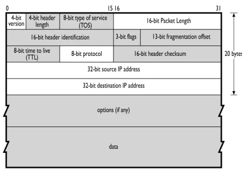
IP passes collections of data as datagrams. Two versions of IP are currently used: versions 4 and 6, referred to as IPv4 and IPv6, respectively. IPv4 still constitutes the vast majority of IP traffic in the Internet. IPv6 usage is growing, and both versions are fully supported by the SiLK tools. Figure1.2shows the breakdown of IPv4 datagrams. Fields that are not recorded by the SiLK data collection tools are grayed out. With IPv6, SiLK records the same information, although the addresses are 128 bits, not 32 bits.
Figure 1.2: Structure of the IPv4 Header
4-bit
version 4-bit headerlength
16-bit header identification 3-bit flags 13-bit fragmentation offset 8-bit type of service
(TOS)
8-bit time to live
(TTL) 8-bit protocol 16-bit header checksum 20 bytes 32-bit source IP address
32-bit destination IP address
options (if any)
data
16-bit Packet Length
0 15 16 31
1.1.3
IP Addressing and Routing
IP can be thought of as a very-high-speed postal service. If someone in Pittsburgh sends a letter to someone in New York, the letter passes through a sequence of postal workers. The postal worker who touches the mail may be different every time a letter is sent, and the only important address is the destination. Normally, there is no reason that New York has to respond to Pittsburgh, and if it does (such as for a return receipt), the sequence of postal workers could be completely different.
IP operates in the same fashion: There is a set of routers between any pair of sites, and packets are sent to the routers the same way that the postal system passes letters back and forth. There is no requirement that the set of routers used to pass data to a destination must be the same as the set used for the return trip, and the routes can change at any time.
Most importantly, the only IP address that must be valid in an IP packet is the destination address. IP itself does not require a valid source address, but some other protocols (e.g., TCP) cannot complete without valid source and destination addresses because the source needs to receive the acknowledgment packets to complete a connection. (However, there are numerous examples of intruders using incomplete connections for malicious purposes.)
Structure of an IP Address
The Internet has space for approximately four billion unique IPv4 addresses. While an IPv4 address can be represented as a 32-bit integer, it is usually displayed indotted decimal (or dotted quad) format as a set of four decimal integers separated by periods (dots); for example, 128.2.118.3, where each integer is a number from 0 to 255, representing the value of one byte (octet).
IP addresses and ranges of addresses can also be referenced using CIDR blocks. CIDR is a standard for grouping together addresses for routing purposes. When an entity purchases or leases a range of IP addresses from the relevant authorities, that entity buys/leases a routing block, that is used to direct packets to its network.
CIDR blocks are usually described with CIDR notation, consisting of an address, a slash, and a prefix length. The prefix length is an integer denoting the number of bits on the left side of the address needed to identify the block. The remaining bits are used to identify hosts within the block. For example, 128.2.0.0/16 would signify that the leftmost 16 bits (2 octets), whose value is 128.2, identify the CIDR block and the remaining bits on the right can have any value denoting a specific host within the block. So all IP addresses from 128.2.0.0 to 128.2.255.255, in which the first 16 bits are unchanged, belong to the same block. Prefix lengths range from 0 (all addresses belong to the same unspecified network; there are 0 network bits specified)4 to 32 (the whole address is made of unchanging bits, so there is only one address in the block; the address is a single host).
With the introduction of IPv6, all of this is changing. IPv6 addresses are 128 bits in length, for a staggering 3.4×1038 (340 undecillion or 340 trillion trillion trillion) possible addresses. IPv6 addresses are represented
as groups of eight hexadectets (four hexadecimal digit integers); for example FEDC:BA98:7654:3210:0037:6698:0000:0510
Each integer is a number between 0 and FFFF (the hexadecimal equivalent of decimal 65,535). IPv6 addresses are allocated in a fashion such that the high-order and low-order digits are manipulated most often, with long strings of hexadecimal zeroes in the middle. There is a shorthand of :: that can be used once in each address to represent a series of zero groups. The addressFEDC::3210 is therefore equivalent to FEDC:0:0:0:0:0:0:3210.
IPv4-compatible (::0:0/96) and IPv4-mapped (::FFFF:0:0/96) IPv6 addresses are displayed by the SiLK tools in a mixed IPv6/IPv4 format (complying with the canonical format), with the network prefix displayed in hexadecimal, and the 32-bit field containing the embedded IPv4 address displayed in dotted quad decimal. For example, the IPv6 addresses::102:304(IPv4-compatible) and::FFFF:506:708(IPv4-mapped) will be displayed as::1.2.3.4and::FFFF:5.6.7.8, respectively.
The routing methods for IPv6 addresses are beyond the scope of this handbook—see RFC 4291 (http:// tools.ietf.org/html/rfc4291) for a description. Blocks of IPv6 addresses are generally denoted with CIDR notation, just as blocks of IPv4 addresses are. CIDR prefix lengths can range from 0 to 128 in IPv6. For 4CIDR /0 addresses are used almost exclusively for empty routing tables and are not accepted by the SiLK tools. This effectively means the range for CIDR prefix lengths is 1–32 for IPv4.
1.1. UNDERSTANDING TCP/IP NETWORK TRAFFIC 9
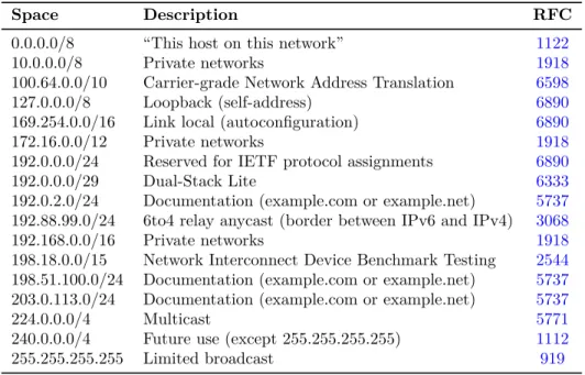
Table 1.1: IPv4 Reserved Addresses
Space Description RFC
0.0.0.0/8 “This host on this network” 1122
10.0.0.0/8 Private networks 1918
100.64.0.0/10 Carrier-grade Network Address Translation 6598 127.0.0.0/8 Loopback (self-address) 6890 169.254.0.0/16 Link local (autoconfiguration) 6890
172.16.0.0/12 Private networks 1918
192.0.0.0/24 Reserved for IETF protocol assignments 6890
192.0.0.0/29 Dual-Stack Lite 6333
192.0.2.0/24 Documentation (example.com or example.net) 5737 192.88.99.0/24 6to4 relay anycast (border between IPv6 and IPv4) 3068 192.168.0.0/16 Private networks 1918 198.18.0.0/15 Network Interconnect Device Benchmark Testing 2544 198.51.100.0/24 Documentation (example.com or example.net) 5737 203.0.113.0/24 Documentation (example.com or example.net) 5737
224.0.0.0/4 Multicast 5771
240.0.0.0/4 Future use (except 255.255.255.255) 1112 255.255.255.255 Limited broadcast 919
example, ::FFFF:0:0/96indicates that the most significant 96 bits of the address ::FFFF:0:0 constitute the network prefix (or network address), and the remaining 32 bits constitute the host part.
In SiLK, the support for IPv6 is controlled by configuration. Check for IPv6 support by running
any_SiLK _tool --version(e.g.,rwcut --version). Then examine the output to see if “IPv6 flow record support” is “yes.”
Reserved IP Addresses
While IPv4 has approximately four billion addresses available, large segments of IP address space are reserved for the maintenance and upkeep of the Internet. Various authoritative sources provide lists of the segments of IP address space that are reserved. One notable reservation list is maintained by the Internet Assigned Numbers Authority (IANA) at http://www.iana.org/assignments/ipv4-address-space. IANA also keeps a list of IPv6 reservations athttp://www.iana.org/assignments/ipv6-address-space.
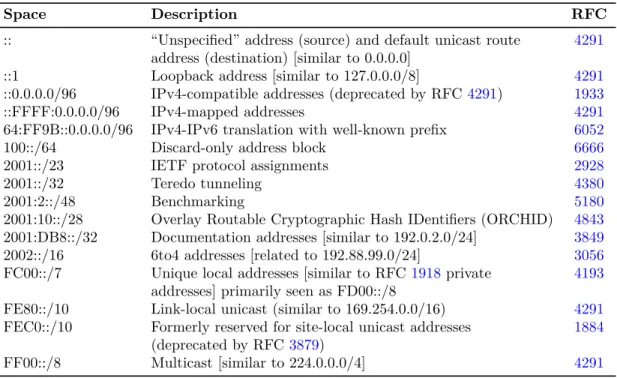
In addition to this list, the Internet Engineering Task Force (IETF) maintains several RFCs that specify other reserved spaces. Most of these spaces are listed in RFC 6890, “Special-Purpose IP Address Registries” at http://tools.ietf.org/html/rfc6890. Table 1.1 summarizes major IPv4 reserved spaces. IPv6 reserved spaces are shown in Table1.2.
Examples in this handbook use addresses in the private and documentation spaces, or addresses that are obviously fictitious, such as 1.2.3.4. This is done to protect the identities of organizations on whose data we tested our examples. Analysts may observe, in real captured traffic, addresses that are not supposed to appear on the Internet. This may be due to misconfiguration of network infrastructure devices or to falsified (spoofed) addressing.
Table 1.2: IPv6 Reserved Addresses
Space Description RFC
:: “Unspecified” address (source) and default unicast route 4291 address (destination) [similar to 0.0.0.0]
::1 Loopback address [similar to 127.0.0.0/8] 4291 ::0.0.0.0/96 IPv4-compatible addresses (deprecated by RFC4291) 1933 ::FFFF:0.0.0.0/96 IPv4-mapped addresses 4291 64:FF9B::0.0.0.0/96 IPv4-IPv6 translation with well-known prefix 6052
100::/64 Discard-only address block 6666
2001::/23 IETF protocol assignments 2928
2001::/32 Teredo tunneling 4380
2001:2::/48 Benchmarking 5180
2001:10::/28 Overlay Routable Cryptographic Hash IDentifiers (ORCHID) 4843 2001:DB8::/32 Documentation addresses [similar to 192.0.2.0/24] 3849 2002::/16 6to4 addresses [related to 192.88.99.0/24] 3056 FC00::/7 Unique local addresses [similar to RFC1918private 4193
addresses] primarily seen as FD00::/8
FE80::/10 Link-local unicast (similar to 169.254.0.0/16) 4291 FEC0::/10 Formerly reserved for site-local unicast addresses 1884
(deprecated by RFC3879)
FF00::/8 Multicast [similar to 224.0.0.0/4] 4291
In general, link-local (169.254.0.0/16 in IPv4, FE80::/10 in IPv6) and loopback (127.0.0.0/8 and ::1) des-tination IP addresses should not cross any routers. Private IP address space (10.0.0.0/8, 172.16.0.0/12, 192.168.0.0/16, and FC00::/7) should not enter or traverse the Internet, so it should not appear at edge routers. Consequently, the appearance of these addresses at these routers indicates a failure of routing pol-icy. Similarly, traffic should not come into the enterprise network from these addresses; the Internet as a whole should not route that traffic to the enterprise network.
1.1.4
Major Protocols
Protocol Layers and Encapsulation
In the multi-layered scheme used by TCP/IP, lower layer protocolsencapsulate higher layer protocols, like envelopes within envelopes. When we open the innermost envelope, we find the message that belongs to the highest layer protocol. Conceptually, the envelopes have metadata written on them. In practice, the metadata are recorded in headers. The header for the lowest layer protocol is sent over the network first, followed by the headers for progressively higher layers. Finally, the message from the highest layer protocol is sent after the last header.
TCP/IP was created before the OSI Reference Model. But if we refer to a layer by its number (e.g., Layer 3 or L3), we always mean the specified layer in that model. While the preceding description of encapsulation is generally true, the model actually assigns protocols to layers based on the protocol’s functions, not its order of encapsulation. This is most apparent with Internet Control Message Protocol (ICMP), which the model assigns to the Network layer (L3), even though its header and payload are encapsulated by IP, which is also
1.1. UNDERSTANDING TCP/IP NETWORK TRAFFIC 11
a Network layer protocol. From here on, we will ignore this fine distinction, and we will consider ICMP to be a Transport layer (L4) protocol because it is encapsulated by IP, a Layer 3 protocol.
Transmission Control Protocol (TCP)
TCP, the most commonly encountered transport protocol on the Internet, is a stream-based protocol that reliably transmits data from the source to the destination. To maintain this reliability, TCP is very complex: The protocol is slow and requires a large commitment of resources.
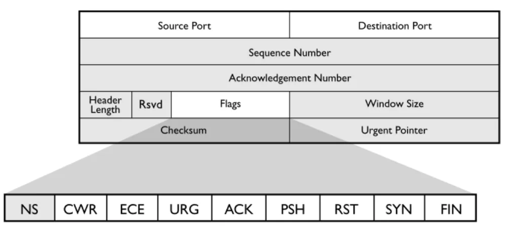
Figure1.3shows a breakdown of the TCP header, which adds 20 additional bytes to the IP header. Conse-quently, TCP packets will always be at least 40 bytes (60 for IPv6) long. As the shaded portions of Figure1.3 show, most of the TCP header information is not retained in SiLK flow records.
Figure 1.3: TCP Header
Rsvd
CWR
NS ECE URG ACK PSH RST SYN FIN
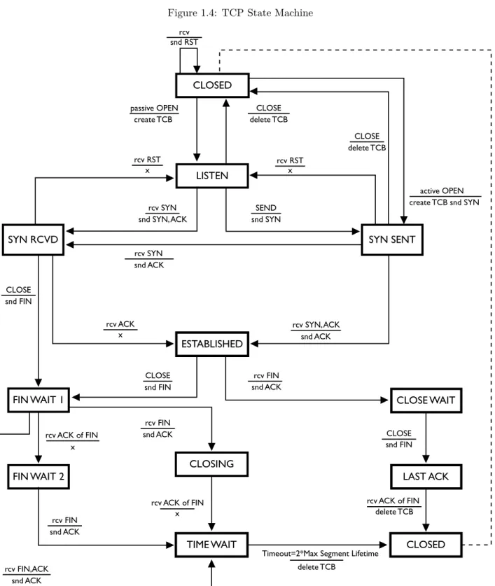
TCP is built on top of an unreliable infrastructure provided by IP. IP assumes that packets can be lost without a problem, and that responsibility for managing packet loss is incumbent on services at higher layers. TCP, which provides ordered and reliable streams on top of this unreliable packet-passing model, implements this feature through a complex state machine as shown in Figure 1.4. The transitions in this state machine are described by labels in a stimulusaction format, where the top value is the stimulating event and the bottom values are actions taken prior to entry into the destination state. Where no action takes place, an “x” is used to indicate explicit inaction.
This handbook does not thoroughly describe the state machine in Figure1.4(seehttp://tools.ietf.org/html/ rfc793 for a complete description), however, flows representing well-behaved TCP sessions will behave in certain ways. For example, a flow for a complete TCP session must have at least four packets: one packet that sets up the connection, one packet that contains the data, one packet that terminates the session, and one packet acknowledging the other side’s termination of the session.5 TCP behavior that deviates from
this provides indicators that can be used by an analyst. An intruder may send packets with odd TCP flag combinations as part of a scan (e.g., with all flags set on). Different operating systems handle protocol violations differently, so odd packets can be used to elicit information that identifies the operating system in use or to pass through some systems benignly, while causing mischief in others.
5It is technically possible for there to be a valid three-packet complete TCP flow: one SYN packet, one SYN-ACK packet containing the data, and one RST packet terminating the flow. This is a very rare circumstance; most complete TCP flows have more than four packets.
Figure 1.4: TCP State Machine SYN SENT LISTEN CLOSED ESTABLISHED CLOSING
TIME WAIT CLOSED
FIN WAIT 2
CLOSE WAIT
LAST ACK SYN RCVD
passive OPEN CLOSE
CLOSE CLOSE CLOSE CLOSE snd FIN rcv FIN rcv FIN rcv FIN snd FIN snd FIN rcv ACK of FIN rcv ACK of FIN x x delete TCB
Timeout=2*Max Segment Lifetime delete TCB rcv ACK of FIN create TCB rcv SYN rcv SYN snd ACK SEND snd SYN snd ACK snd ACK snd ACK snd ACK
rcv ACK rcv SYN, ACK
snd SYN, ACK delete TCB delete TCB active OPEN create TCB snd SYN x rcv RST snd RSTrcv x rcv RST x rcv FIN,ACK snd ACK FIN WAIT 1
1.1. UNDERSTANDING TCP/IP NETWORK TRAFFIC 13
TCP Flags. TCP usesflagsto transmit state information among participants. A flag has two states: high or low; so a flag represents one bit of information. There are six commonly used flags:
ACK: Short for “acknowledge,” ACK flags are sent in almost all TCP packets and used to indicate that previously sent packets have been received.
FIN: Short for “finalize,” the FIN flag is used to terminate a session. When a packet with the FIN flag is sent, the target of the FIN flag knows to expect no more input data. When both have sent and acknowledged FIN flags, the TCP connection is closed gracefully.
PSH: Short for “push,” the PSH flag is used to inform a TCP receiver that the data sent in the packet should immediately be sent to the target application (i.e., the sender has completed this particular send), approximating a message boundary in the stream.
RST: Short for “reset,” the RST flag is sent to indicate that a session is incorrect and should be terminated. When a target receives a RST flag, it terminates immediately. Some implementations terminate sessions using RST instead of the more proper FIN sequence.
SYN: Short for “synchronize,” the SYN flag is sent at the beginning of a session to establish initial sequence numbers. Each side sends one SYN packet at the beginning of a session.
URG: Short for “urgent” data, the URG flag is used to indicate that urgent data (such as a signal from the sending application) is in the buffer and should be used first. The URG flag should only be seen in Telnet-like protocols such as Secure Shell (SSH). Tricks with URG flags can be used to fool intrusion detection systems (IDS).
Reviewing the state machine will show that most state transitions are handled through the use of SYN, ACK, FIN, and RST. The PSH and URG flags are less directly relevant. Two other rarely used flags are understood by SiLK: ECE (Explicit Congestion Notification Echo) and CWR (Congestion Window Reduced). Neither is relevant to security analysis at this time, although they can be used with the SiLK tool suite if required. A ninth TCP flag, NS (Nonce Sum), is not recognized or supported by SiLK.
Major TCP Services. Traditional TCP services have well-known ports; for example, 80 is Web, 25 is SMTP, and 53 is DNS. IANA maintains a list of these port numbers at http://www.iana.org/assignments/service-names-port-numbers. This list is useful for legitimate services, but it does not necessarily contain new services or accurate port assignments for rapidly changing services such as those implemented via peer-to-peer networks. Furthermore, there is no guarantee that traffic seen (e.g., on port 80) is actually web traffic or that web traffic cannot be sent on other ports.
UDP and ICMP
After TCP, the most common protocols on the Internet are UDP and ICMP. While IP uses its addressing and routing to deliver packets to the correct interface on the correct host, Transport layer protocols like TCP and UDP use their port numbers to deliver packets inside the host to the correct process or service. Whereas TCP also provides other functions, such as data streams and reliability, UDP provides only delivery. UDP does not understand that sequential packets might be related (as in streams); UDP leaves that up to higher layer protocols. UDP does not provide reliability functions, like detecting and recovering lost packets, reordering packets, or eliminating duplicate packets. UDP is a fast but unreliable message-passing mechanism used for services where throughput is more critical than accuracy. Examples include audio/video streaming, as well as heavy-use services such as the Domain Name System (DNS). ICMP, a reporting protocol that works in tandem with IP, sends error messages and status updates, and provides diagnostic capabilities like echo.
Figure 1.5: UDP and ICMP Headers
UDP and ICMP Packet Structure
Figure 1.5 shows a breakdown of UDP and ICMP packets, as well as the fields collected by SiLK. UDP can be thought of as TCP without the additional state mechanisms; a UDP packet has both source and destination ports, assigned in the same way TCP assigns them, as well as a payload.
ICMP is a straight message-passing protocol and includes a large amount of information in its first two fields: Type and Code. The Type field is a single byte indicating a general class of message, such as “destination unreachable.” The Code field contains a byte indicating greater detail about the type, such as “port unreachable.” ICMP messages generally have a limited payload; most messages have a fixed size based on type, with the notable exceptions being echo request (ICMPv4 type 8 or ICMPv6 type 128) and echo reply (ICMPv4 type 0 or ICMPv6 type 129).
Major UDP Services and ICMP Messages
UDP services are covered in the IANA webpage whose URL is listed above. As with TCP, the values given by IANA are slightly behind those currently observed on the Internet. IANA also excludes port utilization (even if common) by malicious software such as worms. Although not official, numerous port databases on the web can provide insight into the current port utilization by services.
ICMPv4 types and codes are listed athttp://www.iana.org/assignments/icmp-parameters. ICMPv6 types and codes are listed athttp://www.iana.org/assignments/icmpv6-parameters. These lists are definitive and include references to RFCs explaining the types and codes.
1.2
Using UNIX to Implement Network Traffic Analysis
This section provides a review of basic UNIX operations. SiLK is implemented on UNIX (e.g., Apple®OS X®,
FreeBSD®, Solaris®) and UNIX-like operating systems and environments (e.g., Linux®, Cygwin); consequently
1.2. USING UNIX TO IMPLEMENT NETWORK TRAFFIC ANALYSIS 15
1.2.1
Using the UNIX Command Line
UNIX uses a program known as a shell to obtain commands from a user and either perform the task described by that command or invoke another program that will. Linux usually uses Bash (Bourne-Again SHell) for its shell. When the shell is ready to accept a command from the user, it displays a string of characters known as a prompt to let the user know that he or she can enter a command now. Besides notifying the user that a command can be accepted at this time, the prompt may convey additional information. The choice of information to be conveyed may be made by the user by providing a prompt template to the shell. In this handbook, the prompt will appear as in Example1.1.
Example 1.1: A UNIX Command Prompt
<1>$
The integer between angle brackets will be used to refer to specific commands in examples. Commands can be invoked by typing them directly at the command line. UNIX commands are typically abbreviated English words and accept space-separated parameters. Parameters are just values (like filenames), an option-name/value pair, or just an option name. Option names are double dashes followed by hyphenated words, single dashes followed by single letters, or (rarely) single dashes followed by words (as in thefindcommand). Table 1.3 lists some of the more common UNIX commands. To see more information on these commands typemanfollowed by the command name. Example1.2and the rest of the examples in this handbook show the use of some of these commands.
1.2.2
Standard In, Out, and Error
Many UNIX programs, including most of the SiLK tools, have a default for where to obtain input and where to write output. The symbolic filenames stdin, stdout, and stderr are not the names of disk files, but rather they indirectly refer to files. Initially, the shell assigns the keyboard to stdin and assigns the screen to stdout and stderr. Programs that were written to read and write through these symbolic filenames will default to reading from the keyboard and writing to the screen. But the symbolic filenames can be made to refer indirectly to other files, such as disk files, through shell features calledredirection andpipes.
Output Redirection
Some programs, like cat and cut, have no way for the user to tell the programdirectly which file to use for output. Instead these programs always write their output to stdout. The user must inform UNIX, not the program, that stdout should refer to the desired file. The program then only knows its output is going to stdout, and it’s up to UNIX to route the output to the desired file. One effect of this is that any error message emitted by the program that refers to its output file can only display “stdout,” since the actual output filename is unknown to the program.
The shell makes it easy to tell UNIX that you wish to redirect stdout from its default (the screen) to the file that the user specifies. This is done right on the same command line that runs the program, using the greater than symbol (>) and the desired filename (as shown in Command 1 of Example1.3).
SiLK tools that write binary (non-text) data to stdout will emit an error message and terminate if stdout is assigned to a terminal device. Such tools must have their output directed to a disk file or piped to a SiLK tool that reads that type of binary input.
Table 1.3: Some Common UNIX Commands Command Description
cat Copies streams and/or files onto standard output (show file content) cd Changes [working] directory
chmod Changes file-access permissions. Needed to make script executable cp Copies a file from one name or directory to another
cut Isolates one or more columns from a file date Shows the current or calculated day and time echo Writes arguments to standard output
exit Terminates the current shell or script (log out) with an exit code export Assigns a value to an environment variable that programs can use file Identifies the type of content in a file
grep Displays from a file those lines matching a given pattern head Shows the first few lines of a file’s content
kill Terminates a job or process
less Displays a file one full screen at a time
ls Lists files in the current (or specified) directory
-l(for long) parameter to show all directory information man Shows the online documentation for a command or file mkdir Makes a directory
mv Renames a file or moves it from one directory to another ps Displays the current processes
pwd Displays the working directory rm Removes a file
sed Edits the lines on standard input and writes them to standard output sort Sorts the contents of a text file into lexicographic order
tail Shows the last few lines of a file
time Shows the execution time of a command
top Shows the running processes with the highest CPU utilization uniq Reports or omits repeated lines. Optionally counts repetitions wc Counts the words (or, with-lparameter, counts the lines) in a file which Verifies which copy of a command’s executable file is used
$(...) Inserts the output of the contained command into the command line
1.2. USING UNIX TO IMPLEMENT NETWORK TRAFFIC ANALYSIS 17
Example 1.2: Using Simple UNIX Commands
<1>$ echo Here are some simple commands : Here are some simple commands :
<2>$ date
Thu Jul 3 15:56:24 EDT 2014 <3>$ date -u
Thu Jul 3 19:56:24 UTC 2014
<4>$ # This is a comment line . It has no effect . <5>$ # The next command lists my running processes <6>$ ps -f
UID PID PPID C STIME TTY TIME CMD user1 8280 8279 0 14:43 pts /2 00:00:00 -bash user1 10358 10355 1 15:56 pts /2 00:00:00 ps -f <7>$ cat animals . txt
Animal Legs Color --- ---- ---fox 4 red gorilla 2 silver spider 8 black moth 6 white <8>$ file animals . txt animals . txt : ASCII text <9>$ head -n 3 animals . txt Animal Legs Color --- ---- ---fox 4 red <10>$ cut -f 1,3 animals . txt Animal Color --- ---fox red gorilla silver spider black moth white
Example 1.3: Output Redirection
<1>$ cut -f 1,3 animals . txt > animalcolors . txt <2>$ cat animalcolors . txt Animal Color --- ---fox red gorilla silver spider black moth white <3>$ rm animalcolors . txt <4>$ ls animalcolors . txt
Input Redirection
A very few programs, like tr, have no syntax for specifying the input file and rely entirely on UNIX to connect an input file to stdin. The shell provides a method for redirecting input very similar to redirecting output. You specify a less than symbol (<) followed by the input filename as shown in Command 2 of Example1.4.
Example 1.4: Input Redirection
<1>$ # Translate hyphens to slashes <2>$ tr - / <animals . txt
Animal Legs Color ////// //// ///// fox 4 red gorilla 2 silver spider 8 black moth 6 white Pipes
The real power of stdin and stdout becomes apparent with pipes. A pipe connects the stdout of the first program to the stdin of a second program. This is specified in the shell using a vertical bar character (|), known in UNIX as the pipe symbol.
Example 1.5: Using a Pipe
<1>$ head -n 4 animals . txt | cut -f 1,3 Animal Color
--- ---fox red gorilla silver
In Example1.5, theheadprogram read the first four lines from the animals.txt file and wrote those lines to stdout as normal, except that stdout does not refer to the screen. Thecutprogram has no input filename specified and was programmed to read from stdin when no input filename appears on the command line. The pipe connects the stdout of head to the stdin of cutso thathead’s output lines become cut’s input lines without those lines ever touching a disk file. cut’s stdout was not redirected, so its output appears on the screen.
Here-Documents
Sometimes we have a small set of data that is manually edited and perhaps doesn’t change from one run of a script to the next. If so, instead of creating a separate data file for the input, we can put the input data right into the script file. This is called a here-document, because the data are right here in the script file, immediately following the command that reads them.
1.2. USING UNIX TO IMPLEMENT NETWORK TRAFFIC ANALYSIS 19
Example 1.6 illustrates the use of a here-document to supply several filenames to a SiLK program called rwsort. Therwsortprogram has an option called--xargstelling it to get a list of input files fromstdin. The here-document supplies data tostdin and is specified with double less than symbols (<<), followed by a string that defines the marker that will indicate the end of the here-document data. The lines of the script file that follow the command are input data lines until a line with the marker string is reached.
Example 1.6: Using a Here-Document
<1>$ rwsort --xargs -- fields = sTime --output - path = week .rw <<END -OF - LIST sunday .rw monday .rw tuesday .rw wednesday .rw thursday .rw friday .rw saturday .rw END -OF - LIST
<2>$ rwfileinfo -- fields =count - records * day .rw week .rw
Named Pipes
Using the pipe symbol, a script creates anunnamed pipe. Only one unnamed pipe can exist for output from a program, and only one can exist for input to a program. For there to be more than one, you need some way to distinguish one from another. The solution isnamed pipes.
Unlike unnamed pipes, which are created in the same command line that uses them, named pipes must be created prior to the command line that employs them. As named pipes are also known asFIFOs (for First In First Out), the command to create one is mkfifo (make FIFO). Once the FIFO is created, it can be opened by one process for reading and by another process (or multiple processes) for writing.
Scripts that use named pipes often employ another useful feature of the shell: running programs in the background. In Bash, this is specified by appending an ampersand (&) to the command line. When a program runs in the background, the shell will not wait for its completion before giving you a command prompt. This allows you to issue another command to run concurrently with the background program. You can force a script to wait for the completion of background programs before proceeding by using the wait command.
SiLK applications can communicate via named pipes. In Example1.7, we create a named pipe (in Command 1) that one call torwfilter(in Command 2) uses to filter data concurrently with another call torwfilter (in Command 3). Results of these calls are shown in Commands 5 and 6. Using named pipes, sophisticated SiLK operations can be built in parallel. A backslash at the very end of a line indicates that the command is continued on the following physical line.
Example 1.7: Using a Named Pipe
<1>$ mkfifo / tmp / namedpipe1
<2>$ rwfilter --start - date =2014/03/21 T17 --end - date =2014/03/21 T18 \ --type = all -- protocol =6 \
--fail =/ tmp / namedpipe1 --pass = stdout \ | rwuniq -- fields = protocol --output - path = tcp . out & <3>$ rwfilter / tmp / namedpipe1 -- protocol =17 --pass = stdout \
| rwuniq -- fields = protocol --output - path = udp . out & <4>$ wait
<5>$ cat tcp . out pro | Records |
6| 34866860| <6>$ cat udp . out pro | Records |
17| 17427015|
<7>$ rm / tmp / namedpipe1 tcp . out udp . out
1.2.3
Script Control Structures
Some advanced examples in this handbook will use control structures available from Bash. The syntax forname inword-list-expression; do. . . done
indicates a loop where each of the space-separated values returned by word-list-expression is given in turn to the variable indicated byname(and referenced in commands as $name), and the commands betweendo anddoneare executed with that value. The syntax
whileexpression; do. . . done
indicates a loop where the commands betweendoanddoneare executed as long as expressionevaluates to true.
Chapter 2
The SiLK Flow Repository
This chapter introduces the tools and techniques used to store information about sequences of packets as they are collected on an enterprise network for SiLK (referred to as “network flow” or “network flow data” and occasionally just “flow”). This chapter will help an analyst become familiar with the structure of network flow data, how the collection system gathers network flow data from sensors, and how to access those data. Upon completion of this chapter you will be able to
• describe a network flow record and the conditions under which the collection of one begins and ends
• describe the types of SiLK flow records
• describe the structure of the SiLK flow repository
• use therwsiteinfocommand to organize and display information from the site configuration file
2.1
What Is Network Flow Data?
NetFlow™ is a traffic-summarizing format that was first implemented by Cisco Systems® primarily for
accounting purposes. Network flow data (or network flow) is a generalization of NetFlow. Network flow data are collected to support several different types of analyses of network traffic (some of which are described later in this handbook).
Network flow collection differs from direct packet capture, such as withtcpdump, in that it builds a summary of communications between sources and destinations on a network. For NetFlow, this summary covers all traffic matching seven relevant keys: the source and destination IP addresses, the source and destination ports, the Transport-layer protocol, the type of service, and the interface. SiLK uses five of these attributes
to constitute theflow label: 1. source IP address 2. destination IP address 3. source port 4. destination port 5. Transport-layer protocol
These attributes (also known as thefive-tuple), together with the start time of each network flow, distinguish network flows from each other.
A network flow often covers multiple packets, which are grouped together under common labels. A flow record thus provides the label and statistics on the packets covered by the network flow, including the number of packets covered by the flow, the total number of bytes, and the duration and timing of those packets.
Because network flow is a summary of traffic, it does not contain packet payload data, which are expensive to retain on a large, busy network. Each network flow record created by SiLK is very small (it can be as little as 22 bytes but is determined by several configuration parameters), and even at that size you may collect many gigabytes of flow records daily on a busy network.
2.1.1
Structure of a Flow Record
A flow file is a series of flow records. A flow record holds all the data SiLK retains from the collection process: the flow label fields, start time, number of packets, duration of flow, and so on. All the fields in the flow record are listed in Table3.11on page 59.
Some of the fields are actually stored in the record, such as start time and duration. Some fields are not actually stored; rather, they are derived either wholly from information in the stored fields or from a combination of fields stored in the record and external data. For example, end time is derived by adding the start time and the duration. Source country code is derived from the source IP address and a table that maps IP addresses to country codes.
2.2
Flow Generation and Collection
Every day, SiLK may collect many gigabytes of network flow data from across the enterprise network. Given both the volume and complexity of these data, it is critical to understand how these data are recorded. This section reviews the collection process and shows how data are stored as network flow records.
A network flow record is generated by sensors throughout the enterprise network. The majority of these may be routers, although specialized sensors, such asyaf(http://tools.netsa.cert.org/yaf/), also can be used to avoid artifacts in a router’s implementation of network flow or to use non-device-specific network flow data formats, such as IPFIX (see http://tools.ietf.org/html/rfc7011for definitions and the IPFIX protocol description andhttp://www.iana.org/assignments/ipfixfor descriptions of the IPFIX information elements), or for more control over network flow record generation.6 yafalso is useful when a data feed from a router is 6yafalso may be used to convert packet data to network flow records via a script that automates this process. See Section4.2.
2.2. FLOW GENERATION AND COLLECTION 23
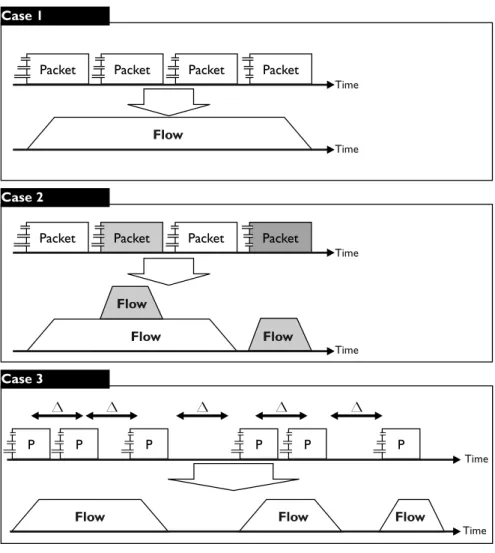
not available, such as on a home network or on an individual host. A sensor generates network flow records by grouping together packets that are closely related in time and have a common flow label. “Closely related” is defined by the sensor and typically set to around 30 seconds. Figure2.1shows the generation of flows from packets. Case 1 in that figure diagrams flow record generation when all the packets for a flow are contiguous and uninterrupted. Case 2 diagrams flow record generation when several flows are collected in parallel. Case 3 diagrams flow record generation when timeout occurs, as discussed below.
Figure 2.1: From Packets to Flows
Network flow is an approximation of traffic, not a natural law. Routers and other sensors make a guess when they decide which packets belong to a flow. These guesses are not perfect; there are several well-known phenomena in which a long-lived session will be split into multiple flow records:
1. Active timeout is the most common cause of a split network flow. Network flow records are purged from the sensor’s memory and restarted after a configurable period of activity. As a result, all network flow records have an upper limit on their duration that depends on the local configuration. A typical value would be around 30 minutes.