Published online October 16, 2014 (http://www.sciencepublishinggroup.com/j/ijmea) doi: 10.11648/j.ijmea.s.2015030101.15
ISSN: 2330-023X (Print); ISSN: 2330-0248 (Online)
Wall flows and their applications
Karel Adamek
1, Dusan Cejka
2, Zden
ě
k Mecl
3, Jaroslav Pelant
41VUTS – Centre of Machinery Research, Liberec, Czech Rep 2KBA- Grafitec, Dobruska, Czech Rep
3PEGAS Nonwovens, Znojmo, Czech Rep
4VZLU – Aeronautical Research and Testing Institute, Praha, Czech Rep
Email address:
[email protected] (K. Adamek), [email protected] (D. Cejka), [email protected] (Z. Mecl), [email protected] (J. Pelant)
To cite this article:
Karel Adamek, Dusan Cejka, Zdeněk Mecl, Jaroslav Pelant. Wall Flows and their Applications. International Journal of Mechanical
Engineering and Applications. Special Issue: Moving Forward to Monitory Democracy: Citizens Engagement in Scrutinizing Election
Process in Indonesian 2014 General Election. Vol. 3, No. 1-1, 2015, pp. 28-32. doi: 10.11648/j.ijmea.s.2015030101.15
Abstract:
So-called wall flows are usable in many technical applications as a simple and reliable device for exhausting of light materials as dust, smoke, hot air, etc. In another cases, such flows can make troubles by treatment of light materials as fibers, etc. and it is necessary to suppress the wall effects by suitable design adjustments. But there is described a useful effect of wall flows on quality of fibrous product, too.Keywords:
Numerical Flow Simulation, Wall Effect, Wall Flow1. Introduction
So-called wall flows are usable in many technical applications as a simple and reliable device for exhausting of light materials as dust, smoke, hot air, etc. But in other cases, such flows can make troubles by treatment of light materials as fibers, etc.
This text presents typical cases of both kinds of all flows – positive influence in exhausting nozzles and negative influence at rotating drums.
2. Flow Around Rotating Drums
2.1. Carding Machine [1], [2], [3]
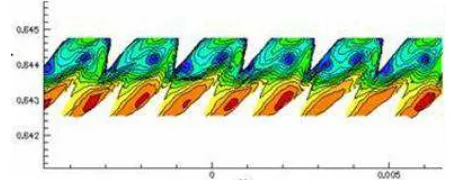
The surface of carding cylinder is spiked by many small needles. The aim of it is the stripping and alignment of elementary fibers and to create the initial material layer for the following operation of spinning. The question is what could be the effect of increased rotation on this operation – maybe the aligned fibers will be dissipated again? The following results did not confirm this misgiving – the aerodynamic forces, creating during the described cylinder rotation, are much smaller comparing with the inertial ones, here first of all, the friction between needles and fibers during the stripping process. In Fig. 2.1-1, there are the velocity isolines in the space between two concentric spiked cylinders (as stator and rotor).
The field is repeating periodically.
Figure 2.1-1. Velocity isolines between rotor and stator of carding machine
In Fig. 2.1-2, there is velocity field in the area of "contact" of carding cylinder (small dents) and removable cylinder (smaller diameter, larger dents). Here, we can see how the some air volume is drifted together with the rotating profiled surface so that in the point of „contact“ of both cylinders, the drifted air cannot pass through this narrow gap and some part of it is reversing back and is flowing out into the surroundings in the direction opposite to the rotation – highlighted by color.
2.2. Production of Nonwoven Layer [4], [5], [6], [7]
This case is similar to the previous. After Fig. 2.2-1, the layer from chemical fibers is coming in horizontal direction from the left between the pair of heated calendaring drums, one of them is furnished by small surface protrusions. The fibrous layer is melted in those contact points and in such manner it receives some tenacity, necessary for next manipulation, sewing, etc. At the same time, the permeability, suction capacity, softness and others usable characteristics of such a product must be kept.
Figure 2.2-1. Streamlines around a pair of rotating drums in viscous
surroundings
From Fig. 2.2-1 it is clear that together with both rotating surfaces some air layer of surroundings is moving, too. In the inlet wedge – left – both air flows are collided and flowing in the direction opposite to the fibrous layer movement horizontally left because the air flow cannot pass through the contact area of both cylinders. In the outlet wedge – right - the situation is similar. Along both rotating surfaces, the moving air layers begin to create and are moving together with the rotating surfaces up and down. Thereby on the right side, there arises some area of under pressure, balanced by the air inlet from the right surroundings.
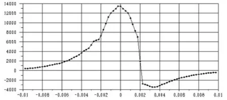
The result of this action there is the pressure profile in the horizontal plane after Fig. 2.2-2. On the left side, the pressure is increasing over the barometric pressure of the surroundings until the maximum, then it decreases sharply onto the value under the barometric pressure and then it is fluently increasing again on the barometric pressure of the surroundings.
Figure 2.2-2. Pressure profile in horizontal plane between two rotating
drums
This global view in a two-dimensional model is completed by a three-dimensional modeling of the detailed flow field. Fig.
2.2-3 (left) presents the surface detail of one of the calendaring drums equipped by small protrusions, colored by dynamic pressure or velocity respectively. The drum diameter is of 3 orders higher compared to the protrusions high; therefore, it is possible to count with linear movement of such surface in immovable surroundings.
Figure 2.2-3. Surface of calendaring drum, colored by dynamic pressure (left),
peripheral component of velocity (right)
The result of such interaction is presented at several figures of the flow field. Fig. 2.2-3 (right) presents the peripheral component of velocity (rotational velocity of 15 m/s, here presented as vertical). It is visible that the velocity of the close surrounding of each protrusion is equal to the velocity of the rotating surface, between the protrusions, the velocity is smaller, and the processed fibrous layer is moved by the rotational velocity as the complete.
Figure 2.2-4. Axial (left) and radial (right) component of velocity
The next Fig. 2.2-4 presents the axial velocity component (left) and the radial one (right). Both those components are considerably (10 times) smaller comparing with the peripheral one; they are created by secondary flows among individual protrusions, only.
Just the effect of those cross components of velocity or dynamic pressures respectively can cause some softening of the homogenous fiber layer, which can obtain in such a manner larger voluminosity and softness comparing to the original layer. Of course, the local melting must be the smallest as possible, large areas of melted, then rigid, materials must be prevented.
2.3. Pressing Cylinder
created by such velocity or pressure field respectively are negligible, comparing to mass forces, i.e. centrifugal and inertial effects of transported sheet and of its rigidity.
Figure 2.3-1. Field of velocity (left) and pressure (right) around rotating
feeding cylinder
3. Wall Effect Applications
3.1. Suction Nozzle
For exhausting and transport of light materials, as for instance short fibers, hot air, fume, etc., the system based on the so-called wall effect can be used [9], etc. The principle is given in Fig. 3.1-1 – the radial inlet through a narrow gap, its one edge is sharp (rectangular) and the second one is well rounded. The outgoing air flow is separating from the sharp edge and is attached to the rounded one. In such a manner the radial flow is changed onto the axial one and from the opposite side it can be drawn in significant volume of secondary flow together with possible transported particles, impurities, etc. The whole system is very simple, reliable, and effective and of very low noise level. Comparing with a classical system of high-speed exhaust fan with motor, filtering container, etc., here, there are two simple turned parts, only. The device is used in several technical applications, as for instance in automatic weft repair on air jet looms for very heavy technical cloths.
Figure 3.1-1. Suitable flow image in suction nozzle
Figure 3.1-2. Unsuitable flow image in suction nozzle (inlet too large)
The described effect can be reached then, only, when the
certain ratio of inlet gap width to the rounding radius is kept. Fig. 3.1-1 presents the velocity field of such a nozzle with a suitable design. The small amount of primary flow, incoming upright to the rotation axis (here vertical), is perfectly bent into the axial direction down and at the same time, several times more of secondary flow is exhausted from up. Fig. 3.1-2 shows an unsuitable form with a too large inlet gap. In such a case, the outlet cross section is clogging, some air volume does not attach the rounding and flows in the opposite axial direction – up.
Fig. 3.1-3 presents the design of suction nozzle together with its operational characteristics in Fig. 3.1-4 [10].
Figure 3.1-3. Design of suction nozzle
Figure 3.1-4. Operating characteristic of suction nozzle
It is visible that some amount of primary air V1 can suck in several times more of the secondary air V2, containing light transporting material, impurities (see the curve V2-B). Applying the hose on the nozzle outlet, the pressure loss is increasing and the air volume is decreasing (see the curve V2-S). The described system is not determined as a force device, for such purpose, the classical ejectors are used, but their efficiency is much smaller – the draw air volume is typically about 15% approx. of the primary driving volume.
3.2. Holding on of Fiber Layer
The treated fiber layer is very airy, several meters wide and it is moving by the velocity of 15 m/s along the flat working surface. During the movement, the layer is oscillating and so it is separating from the surface so that the treating effect is insufficient or none.
Figure 3.2-1. Deformation of idealized plate carried by one-side constant
pressing
The working surface consists from many individual blocks after the Fig. 3.2-2. Treated fibrous layer is very airy, so it is possible to model its movement as the movement of air layer along the working surface. Streamlines show that in individual gaps arises some secondary flows, their force effects contribute to the fibrous layer separation from the working surface.
Figure 3.2-2. Streamlines between elements of working surface – rectangular
edges.
When the edges of elements were rounded after Fig. 3.2-3, the original air flow along the working surface is bend down into gap between elements and by such a manner the original pushing effect is changing into suction one.
Figure 3.2-3. Streamlines between elements of working surface – rounded
edges.
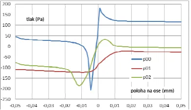
On the Fig. 3.2-4 and Fig. 3.2-5 are presented pressure and velocity profiles in the moving fibrous layer for different shape of edges of individual blocks.
Figure 3.2-4. Pressure profiles along working plane – various rounding
Figure 3.2-5. Velocity profiles along working plane – various rounding
The rectangular edges (signed as 00) are characterized by a high pressure peak at the leading edge of the element. Using a small rounding of edges (signed as 01), we receive under pressure along the whole profile and by this the fibrous layer is well hold at the working surface – the best solution. Using a large rounding (signed as 02), there arises some under pressure at the gap beginning, but followed by over pressure at the end of the gap.
Using a slightly concave surface instead of the planar one, it is warranted a reliable contact of the fibrous layer with the working surface. The radius of the concave surface must be high enough to keep small friction between the fibrous layer and the working surface – due to small tension strength of the treated layer it could tear [11], [12].
3.3. Contactless pressing [13]
Contactless pressing of a sheet to working cylinders is necessary to keep the treated sheet in the defined working area without contact with the adjoining surfaces, due to possible abrasion. The used holding wires or leaders have an abrasive effect, too. Therefore, the contactless pressing was designed, using air flows. One of the original solutions after Fig. 3.3-1 (front view) and Fig. 3.3-2 (ground plan) is not suitable because the area of the pressing of individual sharp air flows is limited and more, it is very noisy.
Figure 3.3-1. Velocity profiles of pressing flows in front view (suppressed
scale)
Figure 3.3-2. Pressure profile of pressing flows on ground plane (sup- pressed
A possible design utilizing the principle of wall effect is presented in Fig. 3.3-3. From the common supply flow, several wall flows flow, each of them draws a multiple volume of air from the surroundings. In such a manner, there arises the air cushion, which prevents the contact of the passing sheet with the surface. Even when the sheet is closer to the surface, the pressure in the air cushion is increasing.
Figure 3.3-3. Scheme of air supply to wall nozzles
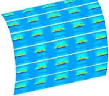
Figure 3.3-4. Traces of pressure fields on the sheet surface
In Fig. 3.3-4, there are traces of pressure fields, created on the sheet surface by a system of wall nozzles. The number and layout of individual nozzles is given by real requirements.
References
[1] J. Pelant, K. Adamek, "Flow around moving surface", ECCOMAS (Europ. Congress on Comput. Meth. in Appl, Sciences and Engineering), University of Jyvaskyla, Finland, 2004. ISBN ….
[2] J. Pelant, K. Adamek, "Luftstroemung entlang des rotierenden Kardenbelags", Chemnitzer Textilmachinen-Tagung, TU Chemnitz, BRD, 2003. ISBN …
[3] K. Adamek, J. Pelant, "Velocity field around rotating surfaces, "XXIInd. int. conf. of departments of thermomech. and fluid mech., Doubice, 2003, ISBN 80-8073-710-1 (in Czech).
[4] K. Adamek, J. Kolar, "Influence of the induced airflow on calendering", EFM11 (Experimental Fluid Mechanics). TU Liberec, JiCin, 2011. ISBN 978-80-7372-784-0.
[5] K. Adamek, "Einfluss der induzierten Luftstroemung beim Kalandrieren", Chemnitzer Textiltechnik Tagung, TU Chemnitz, 2011, ISBN 978-3-9812554-7-8.
[6] K. Adamek, J. Kolar, "Numerical flow simulations used in industrial problems", ECCOMAS (Europ. Congress on Comput. Meth. in Appl. Sciences and Engineering). TU Wien, Austria, 2012, ISBN 978-3-9502481-9-7.
[7] K. Adamek, J. Kolar, "Induced airflow around the calendering drums", Int. Journal of. Mechan. Eng. and Applic. Science PG, 2013, ISSN 2330-0248, ISSN 2330-023x.
[8] K. Adamek, J. Zak, P. Kavan, P. Sidlof, J. Kolar, "Contactless pressing of a sheet", EFM13 (Experimental Fluid Mechanics), TU Liberec, Kutna Hora, 2013, ISBN 978-80-260-5375-0.
[9] J. Bukovsky, "Wall effect applications" Int. conf. Applic. of exp. meth. in fluid. mech., VSDS Zilina, 1984 (in Czech).
[10] K. Adamek, "Automatic weft repair", report VUTS Liberec, 1996, applied on air jet looms Camel, Vega etc. VUTS Liberec, 2000.
[11] Utility design No. CZ - 2012-25916: Zarizeni pro upravu netkane textilie (Device for treating of nonwoven layer), 25.06.2012.