superconductors for magnets of fusion reactors. Studies on configuration of a conductor sample have been carried out for simplification of the conductor sample and its supporting structure. Since sideways force and rotational moment are induced by an asymmetric current component of the sample, the route of feeders and the configuration of terminals of the sample must be optimized. The sample is set at the coaxial position in the center plane of the external field coil because a vertical or radial shift of the sample induces vertical or radial force. According to the structural analysis of the sample chamber, the allowable sideways force of the sample is estimated at 44 kN. Considering the electromagnetic force and the magnetic field at the terminals, representative configurations of one-turn samples are proposed. Concerning the number of turns of the conductor sample, a one-turn or rewound coil is preferred for a fast ramp rate of the sample current.
c
2019 The Japan Society of Plasma Science and Nuclear Fusion Research
Keywords: joint, high current conductor, high magnetic field, Nb3Sn, superconducting magnet, test facility
DOI: 10.1585/pfr.14.3405060
1. Introduction
High current superconductors are needed for magnets of fusion reactors to suppress the high voltage during shut offdue to the coil quench. Degradation of critical currents of Nb3Sn conductors for the ITER magnets was observed
in cyclic loading test [1–3]. The degradation should be more serious in the higher field and the higher current con-ductors. Therefore, a 13 T test facility with a 700 mm cold bore [4] and with 50 kA current leads has been prepared for the research of high-field and high-current supercon-ductors. In order to attain sufficient length of testing region and to apply electromagnetic hoop stress on the supercon-ductors, we propose a coil-shaped conductor sample of few turns, as shown in Fig. 1.
Study on configuration of a conductor sample has been carried out to simplify the sample itself and its sup-porting structure. Since an asymmetric current component of the sample induces sideways force and rotational mo-ment, the route of feeders and the configuration of termi-nals of the sample must be optimized. The sample is set at the coaxial position in the center plane of the external field (EF) coil because a vertical or radial shift of the sam-ple induces vertical or radial force. In addition, the electro-magnetic coupling between the EF coil and the coil-shaped sample must be considered to prevent excess current in-author’s e-mail: [email protected]
∗)This article is based on the presentation at the 27th International Toki
Conference (ITC27) & the 13th Asia Pacific Plasma Theory Conference (APPTC2018).
duced by the rapid change of the other coil current. In this paper, four types of configurations of one-turn samples are proposed, and their electromagnetic force and the magnetic field at the terminals are compared. In addition, the restric-tion on number of turns of the sample is discussed.
2. Four Types of Sample
Configurations
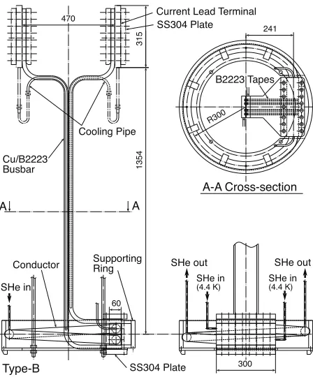
A coil-shaped testing sample is set at the center plane of the EF coil, as shown in Fig. 1. The conductor is wound inside a mechanical supporting ring to withstand large electromagnetic hoop force by itself. Their assembly is hung from a top plate of the cryostat, and installed in the sample chamber, which is evacuated for thermal insu-lation. The conductor sample is cooled with supercritical helium, and the supply gas temperature can be varied from 4.4 K to 50 K. The current leads for the sample are cooled with the same coolant, and their outlets are connected to the room temperature recovery line of the helium refriger-ation system [5]. Since the sample is hung from the top plate, the sideways force induced by an asymmetric cur-rent component mainly at the feeders must be minimized, and the residual sideways force on the sample must be sup-ported from the sample chamber. The allowable sideways force is discussed in Section 3.
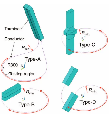
Four types of one-turn samples are proposed as shown in Figs. 1-3. Their three-dimensional views and nominal transverse magnetic fields are shown in Figs. 4 and 5,
re-c
2019 The Japan Society of Plasma
Fig. 1 Setup of the test facility with a 13 T external field coil and a conductor sample (Type-A).
Fig. 2 Configuration of a conductor sample Type-B.
Fig. 3 Configuration of samples Type-C (a) and Type-D (b).
spectively. The minimum bending radii and electromag-netic forces are summarized in Table 1. In the case of the sample current in the co or counter direction to the cur-rent of EF coil, the vertical shift of the sample from the center plane of the EF coil induces attractive or repulsive force toward the center plane, and the radial shift induces repulsive or attractive force toward the center axis. At the sample position where radiusrof 0.3 m and vertical posi-tion from the center planezof 0, the gradient of nominal vertical fielddBz/dris 5.3 T/m, and the nominal radial field
Bris given by
Br=5.25z+34.5z2. (1)
Fig. 4 Three-dimensional view of four types of samples.
Fig. 5 Transverse magnetic field at the conductors and terminals of the samples of Type-A to Type-D.
range.
In the case that the joint length at the terminal is longer than 300 mm, Type-A, where both feeders are pulled up and connected to copper busbars, is preferred because the depth of the sample chamber from the center of the EF coil is limited to 429 mm. The sideways force is relatively strong because the current loop is not closed against the external field at the feeders. In addition, rotational moment is induced by the horizontal forces at the testing region and at the feeders, and vertical force is induced in the feeders inclined against the axis.
Type-B is the simplest one-turn coil with straight minals shorter than 300 mm, as shown in Fig. 2. Both ter-minals are clamped with a set of plates and bolts. Rela-tively weak sideways force is induced by the small diff er-ence of vertical magnetic field between the testing region and the terminals. The bending radius of the conductor near the terminal is around 110 mm, which can be
elon-the position of elon-the terminals toward elon-the center.
Type-C adopts special shape of terminals. Since the horizontal length of the straight section of the terminal is 200 mm, the minimum bending radius is elongated to 150 mm. The rotational moment is small because of the symmetric configuration of the sample against the center plane of the EF coil. In Type-B and Type-C, the termi-nals are located at the highest field area. In order to avoid normal transition from there, the temperature of the ter-minals should be kept lower than the testing region during measurement of critical currents or current sharing temper-atures. The temperature gradient can be realized by prepar-ing a heater on the inlet of coolant for the testprepar-ing region and two outlets of coolant in front of the terminals, as shown in Figs. 2 and 3.
In Type-D, the terminal is pulled away from the center plane to reduce the transverse magnetic field at the feeders and to elongate the minimum bending radius. In the case of incline of 45 degrees, as shown in Fig. 3 (b), transverse magnetic field at the terminal can be reduced to 70% of the testing region, and the minimum bending radius can be elongated to 220 mm. The Type-D is considered to be rea-sonable in the case of short joint length less than 300 mm.
3. Structural Analysis of Sample
Chamber
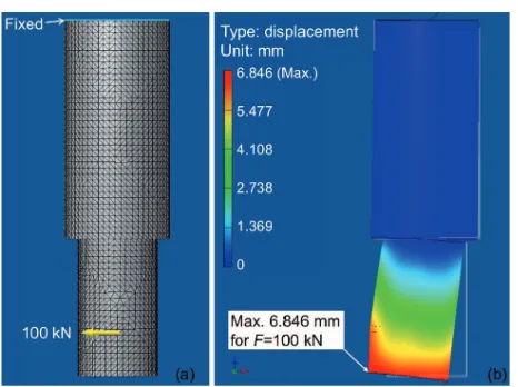
Structural analyses of the sample chamber have been carried out to estimate the allowable sideways force from the sample by using Autodesk Inventor Professional 2010. The sample chamber consists of a top flange, upper cylin-der, middle plate, lower cylincylin-der, and bottom plate. Their thicknesses are 50 mm, 8 mm, 18 mm, 4 mm, and 12 mm, respectively. Tetrahedral solid elements are adopted for all parts. Since the thick top flange is firmly fixed to the top plate of the cryostat with bolts, displacement of the up-per surface of the upup-per cylinder is fixed as a constraint condition of structural analysis. The longitudinal elastic modulus is set at 190.3 GPa, and Poisson’s ratio is 0.305.
in-Fig. 6 Original shape (a) and deformed shape (b) of the sample chamber in the case of the sideways force of 100 kN.
duced at the corner between the middle plate and the lower cylinder. In order to suppress the displacement less than 3 mm which is the average gap between the lower cylinder and the EF coil, the allowable sideways force is 44 kN. In this analysis, the sideways force is applied by uniformly distributed force with the height of 50 mm and the length of arc of 650 mm, which is 30% of the circumference of the lower cylinder, for avoiding peak stress there. In order to estimate the actual local stress at the contact point of the sample, a contact stress analysis is necessary.
4. Consideration on Number of Turns
The electric circuits of the EF coil and the conduc-tor sample are shown in Fig. 7, and inductance of the coils and specifications of the power supply (PS) systems are listed in Table 2. Since both PS systems have bypass lines with diodes for protection of the coil, negative inductive voltage induces increments of the coil current. In the case of a one-turn sample with the same direction of current flow as the EF coil, the EF coil current is increased by 3.6 A at the highest ramp rate of the sample current of -999 A/s. The equivalent current decay time constants of the Nb3Sn and NbTi coil of the EF coil is estimated at 4.9 s
and 15.1 s, respectively, with the quench simulation [6]. Since mutual inductance between the one-turn sample and Nb3Sn/NbTi coil is 2.07/2.34 mH, the induced voltage of
the sample during the shut-offof the EF coil is estimated at 0.44 V. Since the induced voltage is almost proportional to the number of turns of the sample, 10 turns are allowable under the restriction of moderate ramp rate of the sample current around 100 A/s. In the case of the faster ramp rate, a rewound sample, as shown in Fig. 8, or a one-turn sample is preferred.
5. Summary
Four types of conductor samples for the 13 T - 700 mm test facility are proposed. From the viewpoints of the
mag-Fig. 7 Electric circuits for a conductor sample and the EF coil.
Table 2 Coil inductances and specifications of PS systems.
Fig. 8 Configuration of a rewound coil composed with two Type-B conductor samples.
netic field at the terminals and the minimum bending ra-dius, Type-D is considered to be reasonable in the case of a short terminal within 300 mm. In the case of a longer ter-minal, Type-A is suitable. According to the structural anal-ysis of the sample chamber, the allowable sideways force of the sample is estimated at 44 kN. Since this force cor-responds to the length of 70 mm of the current of 50 kA at 12.5 T, the feeders must be as close as possible to each other. Concerning the number of turns of the conduc-tor sample, 10 turns are allowable under the restriction of moderate ramp rate of the sample current around 100 A/s. In the case of the faster ramp rate, a one-turn or rewound coil is preferred.