Automation, Control and Intelligent Systems
2014; 2(1): 1-5Published online March 10, 2014 (http://www.sciencepublishinggroup.com/j/acis) doi: 10.11648/j.acis.20140201.11
Matlab simulation of temperature control of heat
exchanger using different controllers
Neeraj Srivastava, Deoraj Kumar Tanti, Md Akram Ahmad
Electrical Engineering Department, BIT Sindri, Dhanbad, India
Email address:
[email protected] (N. Srivastava), [email protected] (D. K. Tanti), [email protected] (Md A. Ahmad)
To cite this article:
Neeraj Srivastava, Deoraj Kumar Tanti, Md Akram Ahmad. Matlab Simulation of Temperature Control of Heat Exchanger using Different Controllers. Automation, Control and Intelligent Systems. Vol. 2, No. 1, 2014, pp. 1-5. doi: 10.11648/j.acis.20140201.11
Abstract:
Heat exchanger system is widely used in chemical plants because it can sustain wide range of temperature and pressure. The main purpose of a heat exchanger system is to transfer heat from a hot fluid to a cooler fluid, so temperature control of outlet fluid is of prime importance. To control the temperature of outlet fluid of the heat exchanger system a conventional PID controller can be used. Due to inherent disadvantages of conventional control techniques, Fuzzy logic controller is employed to control the temperature of outlet fluid of the heat exchanger system. The designed controller regulates the temperature of the outgoing fluid to a desired set point in the shortest possible time irrespective of load and process disturbances, equipment saturation and nonlinearity.Keywords:
PID Controller, FLC, Heat Exchanger1. Introduction
In practice, all chemical process involves production or absorption of energy in the form of heat. Heat exchanger is commonly used in a chemical process to transfer heat from the hot fluid through a solid wall to a cooler fluid. There are different types of heat exchanger used in the industry but most of the industry use shell and tube type heat exchanger system. Shell and tube heat exchangers are probably the most common type of heat exchangers applicable for a wide range of operating temperatures and pressures. In shell and tube heat exchanger one fluid flows through the tubes and a second fluid flows within the space between the tubes and the shell[1]. The outlet temperature of the shell and tube heat exchanger system has to be kept at a desired set point according to the process requirement. Firstly a classical PID controller is implemented in a feedback control loop so as to achieve the control objectives. PID controller exhibits high overshoots which is undesirable. To minimize the overshoot Fuzzy logic controller is implemented. Fuzzy logic has become one of the most successful of today’s technologies for developing sophisticated control systems. The reason is very simple: Fuzzy logic addresses applications perfectly as it resembles human decision making with an ability to generate precise solutions from certain or approximate information.
The paper is organized as follows: section 2 gives a brief
introduction of Heat exchanger system. Assumptions made and sources of disturbances are also described along with mathematical modeling of system. Section 3 describes PID Controller and its tuning method. Section 4 describes Fuzzy logic controller, its membership function and rule base. Section 5 shows simulation model and its resultant graphs. Section 6 and 7 shows result, discussions and conclusion.
2. Heat Exchanger System
2 Neeraj Srivastava et al.: Matlab Simulation of Temperature Control of Heat Exchanger using Different Controllers
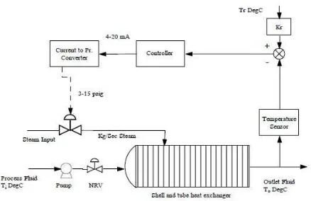
Fig 1. Shell and tube heat exchanger system control scheme.
2.1. Assumptions
Different assumptions have been considered in this research paper. (i) Inflow and the outflow rate of fluid are same, so that the fluid level is maintained constant in the heat exchanger. (ii) The heat storage capacity of the insulating wall is negligible.
A thermocouple is used as the sensing element which is implemented in the feedback path of the control architecture. The temperature of the outgoing fluid is measured by the thermocouple and the output of the thermocouple is sent to the transmitter unit, which eventually converts the thermocouple output to a standardized signal in the range of 4-20 mA. This output of the transmitter unit is given to the controller unit. The controller implements the control algorithm, compares the output with the set point and then gives necessary command to the final control element via the actuator unit. The actuator unit is a current to pressure converter and the final control unit is an air to open valve. The actuator unit takes the controller output in the range of 4-20 mA and converts it in to a standardized pressure signal in the range of 3-15 psig. The valve actuates according to the controller decisions. Fig 1 shows the control scheme adopted in heat exchanger system.
2.2. Sources of Disturbances
There can be two types of disturbances in this process. (i) the flow variation of input fluid (ii) the temperature variation of input fluid.
2.3. Mathematical Modeling of Heat Exchanger System
In this section the heat exchanger system, actuator, valve, sensor are mathematically modeled using the available experimental data. The experimental process data’s are summarized below[2].
Exchanger response to the steam flow gain 50 / /
Time constants 30
Exchanger response to variation of process fluid flow gain
1 / /
Exchanger response to variation of process temperature
gain 3 /
Control valve capacity for steam 1.6 / Time constant of control valve 3
The range of temperature sensor 50 150 Time constant of temperature sensor 10
From the experimental data, transfer functions and the gains are obtained as below.
Transfer function of process Gain of valve 0.13
Transfer function of valve .
Gain of current to pressure converter 0.75 Transfer function of disturbance variables
(i) Flow (dominant). (ii) Temperature
Transfer function of thermocouple .
3. Proportional-Integral-Derivative
(PID) Controller
The mnemonic PID refers to the first letters of the names of the individual terms that make up the standard three-term controller. These are P for the proportional three-term, I for the integral term and D for the derivative term in the controller. PID controllers are probably the most widely used industrial controller. Even complex industrial control systems may comprise a control network whose main control building block is a PID control module. In PID controller Proportional (P) control is not able to remove steady state error or offset error in step response. This offset can be eliminated by Integral (I) control action. Output of I controller at any instant is the area under actuating error signal curve up to that instant. I control removes offset, but may lead to oscillatory response of slowly decreasing amplitude or even increasing amplitude, both of which are undesirable. Derivative (D) control action has high sensitivity. It anticipates actuating error, initiates an early correction action and tends to increase stability of system[2].
Ideal PID controller in continuous time is given as
!" #$
%&*) ' ('# +(
( '
(' , (1)
Laplace domain representation of ideal PID controller is
- ./ ! 1 #$% # +( (2)
3.1. Tuning of PID Controller
Ziegler and Nichols proposed rules for determining values of !, +1 234 +( based on the transient response characteristics of a given plant. Closed loop oscillation based PID tuning method is a popular method of tuning PID controller. In this kind of tuning method, a critical gain
Automation, Control and Intelligent Systems 2014
the value of frequency and time are calculated. Table 1 gives experimental tuning rules based on closed loop oscillation method[3,4].
Table 1. Closed loop oscillation based tuning methods
Type of Controller 67
P 0.5K9
PI 0.45K9 0.
PID 0.6K9 0
The characteristic equation 1 # -case is obtained as below
900 # 420 =# 43 # 0.78
Applying Routh stability criterion in above eq gives
5 24.44
Auxiliary equation is 420 =# 0.78
Substituting ?@ gives @ 0.218
For the PID controller the values of parameters obtained using Ziegler Nichols closed loop oscillation based tuning methods are
! 14.66 +1 14.41 +
Usually, initial design values of PID controller obtained by all means needs to be adjusted
computer simulations until the closed loop system performs or compromises as desired. These adjustments are done in MATLAB simulation.
4. Fuzzy Logic Controller (
The design of fuzzy logic controller is attempted in heat exchanger. The fuzzy controllers are designed with two input variables, error and rate of error
variable (i.e.) the hot water flow rate to the shell side. The mamdani based fuzzy inference system uses linear membership function for both inputs and outputs. For the fuzzy logic controller the input variable
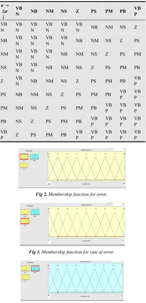
rate of error ∆ , and the output variable is controller output ∆ . Triangular membership functions are used for input variables and the output variable. The universe of discourse of error, rate of error and output are [
4] and [-5, 5] respectively. The rule base framed for shell and tube heat exchangers are tabulated in Table
The structure of the rule base provides negative feedback control in order to maintain stability under any condition. For the evaluation of the rules, the fuzzy reasoning unit of the FLC has been developed using the
inference method[8]. In the particular FLC, the centroid defuzzification method is used. Linguistic variables for error, rate of error and controller output
table 2.[6]
Fig 2, 3 and 4 shows membership functions of different variables implemented in FIS editor in
and fig 5 shows surface view of all variables in 3 dimension[9].
Automation, Control and Intelligent Systems 2014, 2(1): 1-5
the value of frequency and time are calculated. Table 1 gives experimental tuning rules based on closed loop
ed tuning methods.
BC BD
∞ 0
.83T 0
0.5T 0.125T
F 0 in this
78 5# 1 0 (3)
Applying Routh stability criterion in above eq gives
78 5# 1 0 (4)
218 and + 28.82 For the PID controller the values of parameters obtained
oscillation based tuning
+( 3.60
Usually, initial design values of PID controller obtained repeatedly through computer simulations until the closed loop system performs mpromises as desired. These adjustments are done in
Logic Controller (FLC)
The design of fuzzy logic controller is attempted in heat exchanger. The fuzzy controllers are designed with two input variables, error and rate of error and one output water flow rate to the shell side. The mamdani based fuzzy inference system uses linear and outputs. For the fuzzy logic controller the input variables are error and the output variable is controller . Triangular membership functions are used for input variables and the output variable. The universe of discourse of error, rate of error and output are [-13, 13], [-4, ] respectively. The rule base framed for shell and tube heat exchangers are tabulated in Table 3[5,7].
structure of the rule base provides negative feedback control in order to maintain stability under any condition. e fuzzy reasoning unit of the FLC has been developed using the Max-Min fuzzy ]. In the particular FLC, the centroid Linguistic variables for error, rate of error and controller output are tabulated in
Fig 2, 3 and 4 shows membership functions of different variables implemented in FIS editor in MATLAB toolbox surface view of all variables in 3
Table 2. Linguistic variables
VBN Very big
negative
NB Big negative
NM Medium
negative
NS Small negative
Z Zero
Table 3. Rule base for fuzzy logic controller
G H ∆G I
VB
N NB NM NS
VB N VB N VB N VB N VB N
NB VB
N VB N VB N VB N
NM VB
N VB N
VB
N NB
NS VB
N VB
N NB NM
Z VB
N NB NM NS
PS NB NM NS Z
PM NM NS Z PS
PB NS Z PS PM
VB
P Z PS PM PB
Fig 2. Membership function for error
Fig 3. Membership function for rate of error
Fig 4. Membership function for control output
3
Linguistic variables.
PS Small positive
PM Medium
positive
PB Big positive
VBP Very big
positive
Rule base for fuzzy logic controller.
Z PS PM PB VB
P
VB
N NB NM NS Z
NB NM NS Z PS
NM NS Z PS PM
NS Z PS PM PB
Z PS PM PB VB
P
PS PM PB VB
P VB P
PM PB VB
P VB P
VB P
PB VB
P VB P VB P VB P VB P VB P VB P VB P VB P
Membership function for error.
Membership function for rate of error.
4 Neeraj Srivastava et al.: Matlab Simulation of Temperature Control of Heat Exchanger using Different Controllers
Fig 5. 3D Surface view.
5. Simulation
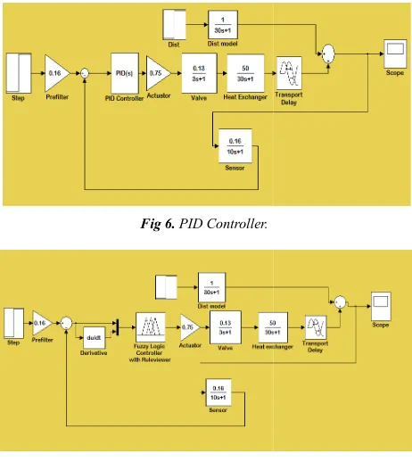
The simulation for different control mechanism discussed above were carried out in Simulink in MATLAB and simulation results have been obtained
shows the PID controller and FLC system block diagram which is simulated in matlab.
Fig 6. PID Controller.
Fig 7. Fuzzy logic controller
Fig 8 and 9 shows step response of PID and FLC system where x axis denote time and y axis denote set point value.
Fig 8. PID Step response
Matlab Simulation of Temperature Control of Heat Exchanger using Different Controllers
The simulation for different control mechanism in Simulink in MATLAB and simulation results have been obtained. Fig 6 and 7 shows the PID controller and FLC system block diagram
Fuzzy logic controller.
PID and FLC system where x axis denote time and y axis denote set point value.
PID Step response.
Fig 9. FLC Step response
6. Simulation Result
To evaluate the performance of the different controllers this paper has considered tw
response of the system. The first parameter is the maximum overshoot and the second parameter is the settling time.
Peak Overshoot: It indicates maximum positive deviation of output with respect to its desired value
defined as[8] %K! 5L'M5 PNO5
Settling Time: It is the time required for the response to reach and stay within a specified tolerance band of its final value. The tolerance band is taken randomly as 2
In this paper control of temperature of hea
done by 2 different controllers. In PID controller we set the parameters by using Ziegler Nichols
After this we simulated the model in MATLAB and tuned the parameters until the response is satisfactory. In step response, we found overshoot and large settling time both of which are undesirable. Moreover there are three tuning parameters which simultaneously be adjusted to get desired result.
Then a Fuzzy logic controller is developed with 9 membership functions for each var
81 rules generated. The response is smooth as well as fastest as compared to PID controllers. So FLC is recommended because it is easy to implement, low cost and no need to know exact plant parameters. Different parameters are tabulated in table
7. Conclusion
In this paper, a comparative study of performance of conventional (PID) and intelligent (FLC)
studied. The aim of the proposed controller is to the temperature of the outgoing fluid of a shell and heat exchanger system to a desi
shortest possible time and minimum or no overshoot After comparing results for different controllers, we obtain that fuzzy logic controller is the one which gives quick response without any oscilla
implement fuzzy logic as it is computer oriented. PID controller, though good for industrial process but due to oscillatory response and large settling time is now going to be replaced by new technology like Fuzzy logic and Neural network.
Matlab Simulation of Temperature Control of Heat Exchanger using Different Controllers
FLC Step response.
Result and Discussion
To evaluate the performance of the different controllers this paper has considered two vital parameters of the step response of the system. The first parameter is the maximum overshoot and the second parameter is the settling time.
It indicates maximum positive of output with respect to its desired value. It is
5 P
Q 100 %
: It is the time required for the response to reach and stay within a specified tolerance band of its final
ance band is taken randomly as 2%. In this paper control of temperature of heat exchanger is done by 2 different controllers. In PID controller we set the parameters by using Ziegler Nichols closed loop method. After this we simulated the model in MATLAB and tuned the response is satisfactory. In step we found overshoot and large settling time both Moreover there are three tuning parameters which simultaneously be adjusted to get desired
Then a Fuzzy logic controller is developed with 9 membership functions for each variable. There were total 81 rules generated. The response is smooth as well as fastest as compared to PID controllers. So FLC is recommended because it is easy to implement, low cost and no need to know exact plant parameters. Different
ated in table 4.
, a comparative study of performance of intelligent (FLC) controllers is studied. The aim of the proposed controller is to regulate outgoing fluid of a shell and tube heat exchanger system to a desired temperature in the
Automation, Control and Intelligent Systems 2014, 2(1): 1-5 5
Table 4. Comparison of different parameters.
Control System Maximum Overshoot
(%) Settling Time (sec)
Feedback PID
Controller 47.2 88
FLC 0 65
Nomenclature
RS Proportional gain
TU Integral time
TV Derivative time
RW Critical gain
T Time period of oscillation
X Angular frequency of oscillation
YW Z Controller transfer function
G Error between desired output and actual output
∆G Rate of error
References
[1] Anton Sodja et.al, "Some Aspects of Modeling of Tube-and-Shell Heat-Exchangers," in Proc of 7th Modelica Corif-, Italy, pp. 716-721, Sep 2009.
[2] Subhransu Padhee, Yuvraj Bhushan Khare, Yaduvir Singh “Internal Model Based PID Control of Shell and Tube Heat Exchanger System,” IEEE, JAN 2011.
[3] Katsuhiko Ogata, “Modern Control Engineering”. 5th edition 2010.
[4] Kiam Heong Ang, Gregory Chong and Yun Li, "PID Control System Analysis, Design, and Technology," IEEE Trans., Control Syst. Technol., vol. 13, no. 4, pp. 559-576, Ju12005.
[5] Mridul Pandey, K. Ramkumar & V. Alagesan “Design of Fuzzy Logic Controller for a Cross Flow Shell and Tube Heat-Exchanger,” IEEE, Mar 2012
[6] Zadeh L.A., Fuzzy relation Equations and Applications to Knowledge Engineering, Kluwer Academic Publishers, Holland, 1989
[7] Larsen P.M., Industrial application of Fuzzy Logic Control, academic press, inc., may, 1979.
[8] BS Manke, “Linear Control System”. 9th edition 2010