National Conference on Advances in Engineering and Applied Science (NCAEAS) 29th January 2018
Organized by : Anjuman College of Engineering and Technology (ACET) Nagpur, Maharashtra, India, In association with
International Journal of Scientific Research in Science and Technology
FPGA controlled Robotics Arm Using VHDL
Mohd. Shoab Sheikh*1, Jahaara Farooqui1, Priyanka Sangole1, Afreen Farooqui1, Dr. Ahmed Sajjad Khan2 1B.E Student, Department of Electronics & Communication Engineering, Acet, Sadar, Nagpur, Maharashtra,
India
2Associate Professor , Department of Electronics & Communication Engineering, Acet, Sadar, Nagpur,
Maharashtra, India
ABSTRACT
The purpose of this project is to design and implement a control system with an FPGA chip to control the movements of a robotic arm. The whole system is composed of the Controller System and the drive circuits, one driver circuit for each motor on the robotic arm. These drive circuits are needed because the Control System does not supply enough power to drive the motors directly. The controller System is implemented on the Spartan -II FPGA chip using VHDL code. Spartan -II FPGA is capable of running at much higher speed but a slow clock is needed to obtain relatively large delays for the output signals. This paper basically focus on the work of our project which is based on motion control using stepper motor .we have successfully done the basic part of project in which we control the stepper motor using FPGA. We have successfully done the programming and simulation part of the project. This project gives the idea regarding controlling servo and stepper motor using interfacing of ULN2803A with FPGA. Consequently, it's important to understand how to work, and what problems exist in designing effective robots. This project will address one of those problems: positional control.
Keywords: Stepper system, position control, FPGA.
I.
INTRODUCTION
Robotic control is an exciting and high challenge research work in recent year. Several solutions to the implementation of digital control system for robot manipulator and mobile robots are proposed in the literatures. But, all of those techniques use the DSP chip or Microcontroller [2]. DSPs and microcontrollers can no longer keep pace with the new generation of applications that require not just higher performance but more flexibility as well –
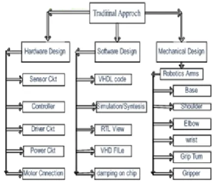
arm with six degrees of freedom. The approach for implementing control systems, Is to design specialized circuits to perform the real-time functions. The whole work follow the sequences of traditional approach basically entire system is classified in three major parts like Hardware design, Software design and Mechanical design. Arm controller robot generally consists of four major parts that is Controller, Arms, Drive Circuit and Sensors. Each motor will have its own control signal. This signal is provided from the FPGA through the drive components. With each movement the motor makes, a Shaft encoder reads the position off of a disk attached to the motor. This position information is sent back to the FPGA Controller so it knows how much farther the motor needs to be turned or if the motor has turned too for [8].
Figure 1. Overall Block Diagram
II.
DESCRIPTION OF COMPONENT USED
A. CONTROLLER
We are using in our project FPGA Chip as controller. It is the heart of robot through all the motion of robot has to be control. A programmed FPGA will contain the VHDL code, which will correlate the inputs to the robotic arm movement. The FPGA system is flexible because it can be easily reconfigured by the end user and reused for many different applications of robotics [7-10].We are going to use the Spartan -IIFPGAs to control the
stepper motor with driver circuit using ULN2003A. Spartan-II FPGAs deliver the performance that allows critical control functions to be implemented in hardware rather than software. By implementing these parameters in hardware, Latency and execution time do not vary: The solution is inherently fast and deterministic. The FPGA based solution provides computation speed of the current control function well below 5 microseconds, which in turn enables high PWM carrier frequency update. The FPGA also allows the torque-control loop response to reach 5 KHz at the -3 dB point. This high-bandwidth torque control loop provides low harmonic current ripple. Interfacing with recently introduced low inductance servomotors and stepper motors such as linear motors becomes much easier [3]. FPGA and FPGA developing system are new technology for developing very large scale integrated circuit. It is known to all, coupling with the fast promotion of SRAM technology, the cost of FPGA decreases while the density increases, so it's lower cost, faster time-to-market and the flexibility make the replacement of ASIC with FPGA a new tread. FPGA has been employed in motor control and robot locomotion successfully and extensively.
FPGA has flexible and programmable architecture, we can add some special needs into our controller, and as the algorithm to regulate the current in the windings of stepper motor that is always improved day by day, we can update our control algorithm and download it to the controller in time [5].The stepper motor is an electrical motor, which converts digital electric input into a rotary motion. Stepper Motor is the one that revolves through a fixed angle for each pulse applied to the logic sequences. By controlling pulse rate stepper motor speed can be controlled. Stepper Motor is also called as a Single Stack Variable Reluctance Motor [1]. The switching is carried out in a sequence; the rotor will rotate with stepped motion. If the power to winding 1 is removed and winding 2 is energized, the rotor will turn 30 degrees, or one step. To rotate the motor continuously, we just apply power to the two windings in sequence. Assuming positive logic, where a 1 means turning on the current through a motor winding, the following control sequences will spin the motor. This sequence uses more power and but produces greater torque.
Table 1.Control sequence for motor winding. Step Coil 1 Coil 2 Coil 3 Coil 4
1 1 0 0 0
2 0 1 0 0
3 0 0 1 0
4 0 0 0 1
5 1 0 0 0
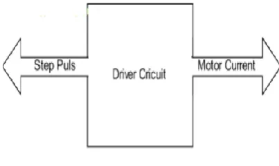
B. DRIVE CIRCUIT SCHEMES
The stepper motor driver circuit has two major tasks: To change the current and flux direction in the phase Windings. To drive a controllable amount of current through the windings, and enabling as short current rise and fall times as
possible for good high speed performance [4]. For a given size of a stepper motor, a limited space is available for the windings. In the process of optimizing a stepper motor drive system, an efficient utilization of the available winding space as well as a matching of driver and winding parameters are of great importance. These motors move something into position and lock it there firmly. Unlike most other tools for moving things, stepper motors can tell you exactly how far and how fast they have moved, and which way they are pointing [6]. The stepper motor controller rapidly distributes precisely timed bursts of electricity to the different coils of the stepper motor and provides the timing to control the speed. It can also count the number of steps travelled-that is, how far the armature has been turned-with computer-like accuracy. The links (the sections between the joints) are moved into their desired position by the drive; a drive is powered by electric motor. The stepper motor driver receives low-level signals from the control system and converts them into electrical (step) pulses to run the motor. One step pulse is required for every step of the motor shaft.
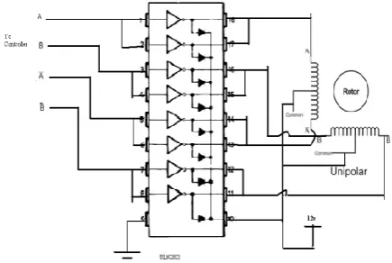
Figure 4. Stepper motor driver board
In our project we are using the stepper board consists of a ULN2803 chip. This consists of 8 Darlington’s to amplify current. A total of 2 unipolar stepper motors can be controlled with this. Bellow figure 4 show the internal connection ULN2803 with Motor.
Figure 5. Interfacing of ULN2803 with motor
C. SENSOR CIRCUIT
We are going to attach the shaft encoder to motor to control the position and send the control signal to the FPGA controller, which provides automatic commutation point alignment for maximum efficiency and torque during closed-loop operation. The encoder disk is firmly connected to the back-shaft of the motor, so that both the back-shaft and the encoder disk rotate at the same rpm. [8]. The rotation of the motor causes the beam of light to be periodically intercepted by the solid parts of the encoder disk creating a sequence of pulses of light, which will be translated by the photo couple's
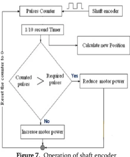
receiver into pulses of electricity [12]. Those pulses of electricity contain all the information we need to implement a closed loop control. The frequency of those pulses is directly proportional the speed of rotation of the shaft (RPM) and the number of those pulses correspond to the angular displacement of the shaft. The more the number of holes in an encoder disk, the higher will be the resolution. Given figure.7 shows the position of shaft encoder between controller and motor. The shaft encoder sensor sends information, in the form of electronic signals back to the controller through the ADC. ADC is use for the purpose of converter accuracy.
Figure 6. Position of shaft encoder
Figure 7. Operation of shaft encoder
D. ROBOTICS ARMS
The arm is the part of the robot that positions the end-effector and sensors to do their pre-programmed business. Our robot having five joint and one gripper. It is having 6 degrees of freedom to allow them to reach any possible point in space within its work envelope. Following TABLE III shows the motor sequences and motor joints. And TABLE II shows the logical sequences arms. As defined earlier there are 6 degrees of freedom to the Robot and each has two possible orientations. The control signals to the motor define the movement of these parts. Each of the joints performs 3 actions (Except the gripper) - Stay, Obtuse angle turn and acute angle turn. So two bits are required to represent each of the movement.
Table 2. logical sequences arms
F E D C B A
00 00 00 00 00 0
01 01 01 01 01 1
10 10 10 10 10
For the Base F:
00 => Stay (Don’t move) 01 => Turn right by 45 Degrees 10 => Turn left by 45 Degrees For the Shoulder E:
00 => Stay (Don’t move)
01 => Turn down by 45 degrees (Acute angle) 10 => Turn up by 45 degrees (Obtuse angle) For the Elbow D:
00 => Stay (Don’t move)
01 => Turn down by 45 degrees (Acute angle) 10 => Turn up by 45 degrees (Obtuse angle) For the Wrist C:
00 => Stay (Don’t move)
01 => Turn down by 90 degrees. 10 => Turn up by 90 degrees. For the Grip Turn B:
00 => Stay (Don’t move)
01 => Turn down by 45 degrees (Acute angle) 10 => Turn up by 45 degrees (Obtuse angle) For the Gripper A:
0 => Hold, 1=> Release.
Table 3. Motor and Motor joint
Motor Motor Joint
Motor A Grip Close
Motor B Grip Turn
Motor C Wrist
Motor D Elbow
Motor E Shoulder
Motor F Base
III.
CONCLUSION
stepper motors simultaneously without increasing the processing time. This advantage makes the system very convenient since it allows the increase of the number of motors, simply using a larger FPGA. We can easily add the flexibility in operation by modify its behavior, changing a parallel ADC for a serial one (or vice-versa) is a minor effort in an FPGA but can be very troublesome in a software solution. Once a technology is carefully set up, we can easily apply it to different systems; we can say it is multipurpose system. We can also reuse a common controller board for many different systems. this work is very useful for new researcher to get the idea of motor control in the field of FPGA and Robot.
IV.
REFERENCES
[1]. Lab views 10, Implementation of Stepper Motor Controller, 2006.
[2]. Ying-Shieh Kung, Gua-Shieh Shu," FPGA-based Motion Control IC for Robot Arm", IEEE-2005, pp 1397-140.
[3]. Jasbinder Bhoot, Strategic Solutions Xilinx, Xcell Journal, Summer 2003.
[4]. Industrial Circuits Application Note ‘Drive circuit basics’, http://library.solarbotics.net. [5]. Zhaojin Wen' Weihai Chen China, "Analysis
of Two-Phase Stepper Motor Driver Based on FPGA" IEEE International Conference on Industrial Informatics 2006, pp 221-226. [6]. Daniel Carrica, Marcos, A. Funes. Novel
Stepper Motor Controller Based on FPGA Hardware Implementation, IEEE/ASME Transactions on mechatronics, Vol. 8 No. 1 March 2003, pp 1083-4435.
[7]. Giuseppe Casalino, Fabio Giorgi, Alessio Turetta, and Andrea Caffaz, "Embedded FPGA-based Control of a Multifingered
Robotic Hand," 2003 IEEE International Conference on Robotics & Automation, Taiwan, 2003, pp 2786-2791.
[8]. Kawahito, J-H. Park, K. Isobe, S. Suhaidi, T. Iida, T. Mizota, "A CMOS Image Sensor Integrating Column-Parallel Cyclic ADCs with On-Chip Digital Error-Correction Circuits", IEEE.Feb.2008, pp 56-595.
[9]. S. B. Shafie, S. Kawahito, "A wide dynamic range image sensor with dual charge storage in a pixel and a multiple sampling technique", Proc. SPIE Electronic Imaging 2008, vol.6816, pp 345-351.
[10]. Sung Su Kim and Seul Jung, "Hardware Implementation of a Real Time Neural Network Controller with a DSP and an FPGA", Proceedings of the IEEE International Conference on Robotics and Automation. New Orleans, LA.2004, pp 4739-4644.
[11]. Swagat Kumar, Amit Shuklay, Ashish Duttaz and Laxmidhar Beherax "Technique for Visual Motor Coordination of a 6 DOF robot manipulator" "Intelligent Control Part of IEEE Multi-conference on Systems and Control" 1-3 October 2007,pp 544-549. [12]. S. Kawahito, "CMOS Sensors for Smart and