Fiber Bragg Grating Modeling,
Characterization and Optimization with
different index profiles
SUNITA UGALE Electronics Engineering Department
S. V. National Institute of Technology, Ichchhanath, Surat, Gujarat, India Email: [email protected]
Dr. V. MISHRA Senior Member IEEE Electronics Engineering Department
S. V. National Institute of Technology, Ichchhanath, Surat, Gujarat, India
Email:
[email protected]Abstract:
This paper presents the modeling and characterization of an optical fiber grating for maximum reflectivity, minimum side lobe power wastage. Grating length and refractive index profile are the critical parameters in contributing to performance of fiber Bragg grating. The reflection spectra and side lobes strength were analyzed with different lengths and different refractive index profiles. Apodization techniques are used to get optimized reflection spectra. The simulations are based on solving coupled mode equations by transfer matrix method that describes the interaction of guided modes.
Keywords:Fiber Bragg Grating, Coupled mode theory, simulation, reflectivity, Apodization.
1. Introduction
Fiber Bragg gratings are spectral filters based on the principle of Bragg reflection. They typically reflect light over a narrow wavelength range and transmit all other wavelengths. When light propagates by periodically alternating regions of higher and lower refractive index, it is partially reflected at each interface between those regions. If the pitch of the grating is properly designed, then all partial reflections add up in phase and can grow to nearly 100%, for a specific wavelength even if the individual reflections are very small. The condition for high reflection is known as Bragg condition. For all other wavelengths the out of phase reflections end up cancelling each other, resulting in high transmission [1, 2].
FBG Sensors are based on the fact that Bragg wavelength changes with change in pitch of the grating and the change in refractive index. Thus, any physical parameter which cause change in above mentioned parameters can be sensed using FBG, by measuring the shift in Bragg wavelength. FBG is the key component for dispersion compensation and WDM. [4, 5, 7].
2. Theory
The propagation of light along a waveguide can be described in terms of a set of guided electromagnetic waves called the modes of waveguide [3, 6]. In optical fibers the core-cladding boundary conditions lead to coupling between the electric and magnetic field components.
Each mode has its specific propagation constants. If the periodic perturbation is introduced alongside the fiber the mode will exchange its power. This phenomenon is known as mode coupling. Fiber gratings can be broadly classified into two types: Bragg gratings (also called reflection and short-period gratings), in which coupling occurs between modes traveling in opposite directions; and transmission gratings (also called long-period gratings), in which the coupling is between modes traveling in the same direction.
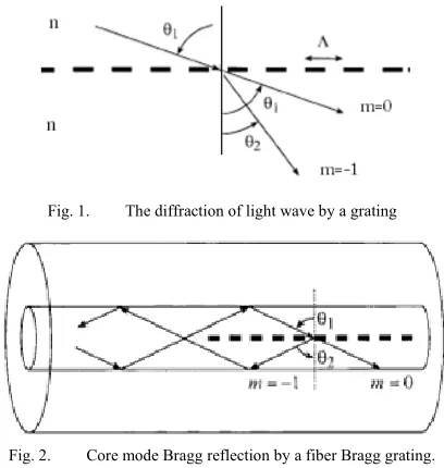
A fiber grating is simply an optical diffraction grating, and thus its effect upon a light wave incident on the grating at an angle can be described by the familiar grating equation:
nsinθ2= nsinθ1 +m (λ/ Λ)
Fig. 1. The diffraction of light wave by a grating
Fig. 2. Core mode Bragg reflection by a fiber Bragg grating.
Fig. 2 illustrates reflection by a Bragg grating of a mode with a bounce angle of θ1 into the same mode traveling in the opposite direction with a bounce angle of θ2=- θ1 .
β is the z component of wave propagation constant k & is the main parameter in describing fiber modes, is simply
β=(2π/λ)neff Where, neff = ncosinθ
The mode remains guided as long as β satisfies the condition n2k<β<n1k Where n1 and n2 are core and cladding refractive index and k=2π/λ
The boundary between truly guided modes and leaky modes is defined by the cutoff condition β=n2k. As soon as β becomes smaller than n2k, power leaks out of the core into the cladding region [10, 11].
3. Modeling
Refer Figure 3, the fiber contains a Bragg grating, of length L and uniform pitch length Λ. The electric fields of the propagating waves can then be expressed as
Ea (z, t)= A(z) ei(ωt-βz) (1)
Eb (z, t)= B(z) ei(ωt+βz) (2)
For the backward and forward propagating waves, respectively
Fig. 3. Propagating waves in Bragg grating
The coupled-mode equations describe their complex amplitudes, A(z) and B(z)
∆
0 ≤ z ≤L ∆ (3)
If we assume that both forward and backward waves enter the grating, then assume the boundary conditions
B(0) = Bo and A(L) = AL. Substituting these boundary conditions into equation 3, we can solve for the
b(z)=B(z)eiβz (4)
The reflected wave, a(0), and the transmitted wave, b(L) can be expressed by means of the scattering matrix 0
= 0 (5)
Substituting a(L)and b(0) from equation 4 into equation 5 we get
∆
∆ (6)
Based on equations 5 and 6, the scattering matrix, we can obtain the transfer-matrix, or
T-matrix equation
0
0 = (7)
Where
∆
(8)
This matrix approach is effective at treating a single grating as a series of separate gratings each having reduced overall lengths and different pitch lengths, and describing each with its own T-matrix. Combining all the matrices yields the properties of the initial non-uniform grating. The resultant system of matrices is treated as an individual matrix
… (9)
Light passing through successive optical elements can be calculated by series of matrices, as such
0
0 = … . . (10)
The characteristics response from Bragg Grating can be fully described by 1. The center wavelength of Grating λB
2. Peak reflectivity Rmax of grating which occur at λB 3. Physical length of Grating L
4. Refractive index of core of optical fiber nco 5. Amplitude of induced core index perturbation ∆n
For a grating with uniform index modulation and period the reflectivity is given by
R L,λ κ sinh SL
∆β sinh SL κ cosh SL
Where
R: Grating reflectivity as a function of both grating length and wavelength L: total length of grating
κ: coupling constant, given by κ=π∆n/λ
∆β: wave vector detuning, given by ∆β=β-(π/Λ) β: fiber core propagation constant, given by β=2πn0/λ
S=√κ2-∆β2
For light at the Bragg grating center wavelength, λB, there is no wave vector detuning and so ∆β= 0. The reflectivity function then becomes
R (L, λ)=tanh2(SL)
4. Results and analysis
Grating type: Volume index Modulation depth: 0.0012 Cladding index: 1.45
Waveguide width and height: 5.25µm Period: 0.5 µm,
Free space wavelength: 1.55 µm
The reflectivity of Uniform FBG changes with different grating lengths as shown in table 1 The reflectivity increases with increase in grating length as well as index difference. Almost after a length of 2.5mm, 100% reflectivity is achieved. Strength of side lobes in reflectivity curve of Uniform FBG increases with increase of grating length and index difference as indicated in table 2.
The power wasted in side lobes can be minimized by applying different index profiles, called as Apodization.
Doping concentration variation limits the index variation to maximum value ∆no. Index inside core after FBG has been printed can be expressed by
n(z) = nco + ∆n0. A(z).nd(z) (11)
where nco- core refractive index, nd(z)-index variation function ∆n0- maximum index variation A(z)-Apodization function
For uniform FBG with no apodization index variation function nd(z) is given as
2
Where Λ: constant grating period, A=1
Table 1. Dependence of reflectivity on grating length and index difference
FBG ∆n0:0.01
Λ=0.5319 ∆n0:0.008 Λ=0.5325 ∆n0: 0.005 Λ=0.5334 ∆n0: 0.003 Λ=0.5339
L mm R R R R
0.5 62.52% 60.24% 53.76% 42.58% 1 94.65% 93.76% 90.80% 83.59% 1.5 99.4% 99.11% 98.51% 96.43% 2 100% 100% 99.7% 99.1% 2.5 100% 100% 100% 100% 5 100% 100% 100% 100% 10 100% 100% 100% 100% 20 100% 100% 100% 100%
R: Reflectivity, ∆n0: index difference, L: Length
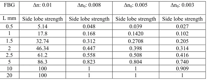
Table 2. Dependence of side lobe strength on grating length and index difference
FBG ∆n: 0.01 ∆n0: 0.008 ∆n0: 0.005 ∆n0: 0.003
L mm Side lobe strength Side lobe strength Side lobe strength Side lobe strength
0.5 5.14 0.048 0.039 0.027
1 17.8 0.168 0.1420 0.102
1.5 32.74 0.312 0.2708 0.205
2 46.34 0.447 0.398 0.314
2.5 61.2 0.558 0.508 0.416
5 86.3 0.823 0.804 0.740
10 100 1 1 0.909
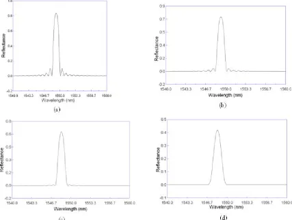
Fig. 4. Reflectance curve for uniform FBG with (a) no apodization, (b) sync apodization, (c) Gaussian Apodization, (d) Raised Cosine Apodization
Apodization function A(z) in equation (11) can be changed to reduce the side lobes as shown in figure (4, 5, 6 & 7 ).
For sinc Apodization /
Where ΛT=sync function parameter
For Gaussian Apodization
4 /2
For Raised cosine Apodization
1 /2
Where α is raised-cosine parameter
5. Conclusion
We have studied the different characteristics of FBG with various grating lengths. The quantitative analysis on maximum reflectivity and side lobe strength reduction is done and following conclusions are obtained. The reflectivity increases with increase in grating length as well as index difference. Almost after a length of 2.5mm, 100% reflectivity is achieved. Strength of side lobes in reflectivity curve of Uniform FBG increases with increase of grating length and index difference which can be reduced by applying apodization.
References
[1] Ho Sze Phing, Jalil Ali, Rosly Abdul Rahman and Bashir Ahmed Thir: Fiber Bragg grating modeling, simulation and characterstics with different grating lenths. Journal of Fundamental Sciences 3 (2007) 167-175.
[2] Reema Sharma, Rajesh Rohilla, Mohit Shrma, Dr. T. C. Manjunath: Design & Simulation of Optical Fiber Bragg Grating Pressure Sensor for minimum attenuation criteria. Journal of Theoretical and Applied Information Technology © 2005-2009 JATIT.
[3] Yanyu Zhao and Joseph C. Palais, Fellow, IEEE: Fiber Bragg Grating Coherence Spectrum Modeling, Simulation, and Characteristics. Journal of lightwave technology, Vol. 15, No. 1, January 1997.
[4] M. Mahmoud, Z. Ghassemlooy: Tunable Fiber Bragg Gratings Modeling and Simulation. Proceedings of the 36th Annual Simulation Symposium (ANSS’03)1080-241X/03 $17.00 © 2003 IEEE
[5] Prasant K. Sahu, Sanjay Kumar C. Gowre, S. Mahapatra, J. C. Biswas: Numerical modeling and simulation of Fibre –Bragg Grating based devices for all-optical communication network. 1-4244-0340-5/06/$20.00 ©2006 IEEE
[6] N.-H. Sun and J.-J. Liau, Y.-W. Kiang, S.-C. Lin, R.-Y. Ro and J.-S. Chiang, H.-W. Chang: Numerical Analysis of Apodized Fiber Bragg Gratings using Coupled mode Theory. Progress In Electromagnetics Research, PIER 99, 289{306, 2009 }
[7] Jaikaran Singh, Dr. Anubhuti Khare, Dr. Sudhir Kumar: Design of Gaussian Apodized Fiber Bragg Grating and its applications. nternational Journal of Engineering Science and Technology Vol. 2(5), 2010, 1419-1424
[8] Turan Erdogan: Fiber Grating Spectra. Journal of Lightwave Technology, Vol. 15, No. 8, August 1997.
[9] Yinghui Cao, Jie Zheng and Yushu Zhang: Numerical modeling of fiber grating. Optik - International Journal for Light and Electron Optics Volume 120, Issue 17, November 2009, Pages 911-915
[10] G. P. Agrawal: Nonlinear Fiber Optics. New York: Academic, 1995.