FORMAL VERIFICATION OF REAL
TIME DISTRIBUTED SYSTEMS USING
B METHOD
AYAMAN M. WAHBA
Computer and Systems Engineering Department, Faculty of Engineering Ain Shams University, Saryat Street, Cairo, 11361, Egypt
NAHLA A. EL-ARABY
Electrical and Electronics Engineering Dept., Canadian International College, New Cairo, Cairo, 11361, Egypt
Abstract:
Throughout the previous years, the complexity and size of digital systems has increased dramatically, as a result design flow phases changed a lot. Simulation used to be the most common procedure to assure the correctness of a system under design, but it cannot exhaustively examine all the execution scenarios of the system. A different approach to validate a system by formally reasoning the system behavior is Formal verification, where the system implementation is checked against the requirements or the properties to be satisfied. The most common paradigms are based on theorem proving, model checking and language containment.
This paper presents an application of the B method to the formalization and verification of a simplified flight control system, as an example of a system consisting of a number of distributed computing devices that are interconnected together through digital communication channels.
Keywords: Formal Verification; B method; Real time systems; Theorem proving.
1. Introduction
People and goods safety are directly affected by the reliability of automated systems. Safety aspects should be considered from early design stages up to operational stages and this needs a very accurate design approach [1]. This becomes more sophisticated in real time systems as real-time systems differ from untimed systems in that the correct behavior relies on computation results plus the time on which they were produced. The resulting state-space explosion makes it infeasible to run a satisfactory number of simulation traces to achieve enough coverage of the state spaces and enough confidence in the design correctness within a project schedule. Even if it were feasible to have extensive coverage of the system, missing only single untested sequence of events may cause the system failure.
Formal verification means to thoroughly investigate the correctness of system designs expressed as mathematical models. Formal verification is a useful and powerful technique for guaranteeing the reliability of systems in design stages [2]. In recent years, several approaches to applying formal verification techniques on automation systems dependability have been proposed. These range from formal verification by theorem proving [3] to formal verification by model-checking [4, 5, 6, 7]. Many achievements in the formal verification of real-time systems are presented in [8], [9], [10], and [11].
already had a remarkable effect on the SLAM project of Microsoft, which plans to include model-checking capability in its Windows driver development kit (DDK) [12].
This paper presents an application of the B method to the formalization and verification of a simplified flight control system, as an example of a system consisting of a number of distributed computing devices that are interconnected together through digital communication channels. Due to the distributed nature, and due to the different tasks performed by theses devices, and for fault tolerant reasons, these devices are working in an asynchronous manner. The problem is how to verify the correctness of such a complex system, knowing that local verification at the level of the individual devices in not sufficient. The verification must be global, and must take into account the asynchronous nature of the system.
This work is based on a previous research [13] that showed how to verify functional and real-time properties in a distributed system, and compared two modeling techniques coupled with two verification tools, the first was the timed automata approach and its verification system UPPALL, the second was LUSTURE based technique, and the SMV verification system.
In this work the B method is used to model and verify the flight control system, as a distributed real time asynchronous system. This formal model provides an abstract reference specification, expressed using a formal mathematical language. B machines have the potential for eliminating any ambiguity, which may remain in the existing semi-formal documentation expressed in natural language. The model also provides a general framework from which other participants may build up and share their contributions.
The paper is organized as follows: section 2 presents the formal verification approaches, section 3 introduces the B-method, then section 4 describes the functionality of the simplified flight control system and its formal model in B, and in section 5 discusses the experimental results and then conclusions and future work are presented in section 6.
2. Formal Verification
Formal specification is defined by the IEEE standard as a specification written in a formal method. Formal methods are particular type of mathematically-based procedures for the specification, development and verification of systems. Performing appropriate mathematical analysis that contributes to the reliability and robustness of a design is the motivation for using formal methods for design. Systems can be formally described at different levels of abstraction.
The formal description can be used to guide further development activities; moreover, it can be used to verify that the requirements for the system being developed have been entirely and precisely specified. A variety of formal methods and notations available are available, like Z notation, VDM and B-Method.
Verification plays a vital role in the design cycle of any safety critical system. The development of any system is not complete without careful testing and verification that the implementation satisfies the system requirements. In the past, verification was an informal process performed by the designer. But as the complexity of systems increased, it became necessary to consider the verification as a separate step in the overall development cycle. Verification techniques can be either based on simulation or based on formal methods. Simulation is based on a model that describes the possible behavior of the system design at hand. This model is executable in some sense, such that a simulator can determine the system’s behavior on the basis of some scenarios. Formal Verification is defined as “establishing properties of hardware or software designs using logic, rather than (just) testing or informal arguments. This involves formal specification of the requirement, formal modeling of the implementation, and precise rules of inference to prove that the implementation satisfies the specification” [14]. Three categories can be used to classify the Formal Verification methods - equivalence checking, model checking and theorem proving.
2.1. Equivalence Checking
Equivalence checking verifies that two designs have the same apparent behaviors (e.g., an optimized design has the same observable behavior as its earlier version). Two distinct types of equivalence checking for digital systems are available according to the type of circuits either combinational or sequential. For combinational systems the two outputs are passed into canonical representation, if the representations are identical the two systems are equivalent.
2.2.Model Checking
In Model checking an automatic process is used to check if a system satisfies a known property. The Model checking process starts by describing the system being verified and its required behavior formally; a formal model of the system is build as a collection of finite state machines, and the behavior is modeled as a set of properties (usually defined in terms of temporal logic formulas). Then, the properties satisfaction is checked automatically by exhaustively exploring the state space of the system. The termination of model checking is guaranteed by the finiteness of the model (there are a finite number of states).
There are various approaches to model checking. They depend on various technical issues such as the choice of the language that is used in expressing the system specifications, the representation of the system, ..etc.
Automatic process of model checking is its main advantage. If the model was selected properly the required properties can be verified in one pass. Moreover, available tools for model-checking provide a trace for each error path in the model. The model checker will either terminate with the answer true indicating the property is satisfied of give a counterexample execution that shows why the property is not satisfied.
Model Checking is not suitable for very large systems as the state space generally grows exponentially with the size of the transition system. This problem is referred to as state explosion problem. Another drawback of model checking is that it operates only on models and the actual implementation might drift from the correct implementation of the model, so the verified model is not equivalent to the actual implementation.
2.3. Theorem Proving
Theorem proving is a pure mathematical or logical approach where the verification problem is described as a theorem in a formal theory.
A formal Theory is a language in which the formulas are written, a set of axioms are developed, and a set of inference rules are used for proving. Theorems can be proved with rules and axioms. A desired property is satisfied if a proof can be constructed from the system axioms and inference rules.
Table.1 shows part of formal description of logical operators used in theorem proving.
Table.1. Formal equivalent logic operators
A formal theory S is defined in [14] by:
(1) A finite alphabet is given; a finite sequence of these symbols is called an expression of S. (2) Subsets of the expressions of S are called well-formed formulas of S.
(3) A finite set of the well-formed formulas of S are called axioms of S.
(4) A finite set of rules of inference is given. A rule of inference allows the derivation of a new well-formed formula from a given finite set of well-well-formed formulas.
A formal proofin S is a finite sequence of well-formed formulas: f1, f2,…, fn, such that for every i, formula fi is either an axiom or can be derived by one of the rules of inference given the set of formulas {f1, f2, …, fi-1}. Traditionally, the last well-formed formula in a formal proof is called a theorem of S, and the formal proof is a proof of this theorem.
Example:
x. x = y x = y holds in all interpretations
x. x + x = 2x holds in obvious arithmetic interpretations, but not all interpretations. x. x ≥ 0 y. x = y2 holds in R but not in Z.
drawback is that it needs human interaction for invariant analysis. Another disadvantage is the high computational complexity and that it does not provide concrete counter-examples when a query is not valid. 3. B-Method
The B method is a model-oriented formal method for engineering software systems developed by Abrial [15]. It is a comprehensive formal method that covers the entire development cycle. The method is based on the mathematical principles of set theory and predicate calculus while its semantics is given using a variant of Dijkstra's weakest precondition calculus [16].
A hierarchy of components that are described using the Abstract Machine Notation (AMN) constitutes a B specification.
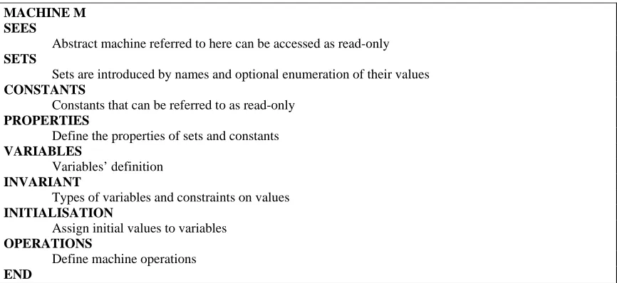
Each component in a specification represents a state machine where a set of variables defines its state and a set of operations query and modify that state. Generalized substitutions describe state transitions. Constraints on the operation and variable types are described as invariants of a machine. In B models Abstract Machines are the top-level components describing state machines in an abstract way. Refinements are another type of components that exist in a B specification; they represent enriched versions of either an Abstract Machine or another Refinement. In a Refinement the interface and behavior of the original machine has to be preserved but the data and operations can be reformulated. The last type of components is Implementations where ultimate refinement of an Abstract Machine is described; both data and operations need to be implementable in a high-level programming language. An Implementation may rely on the operations and data imported from Abstract Machines. Figure 1 shows the structure of a B machine.
Syntax and type checking can be performed on a system modeled in B. Also a B model consistency can be verified to check the preservation of invariants and the correctness of all refinement steps.
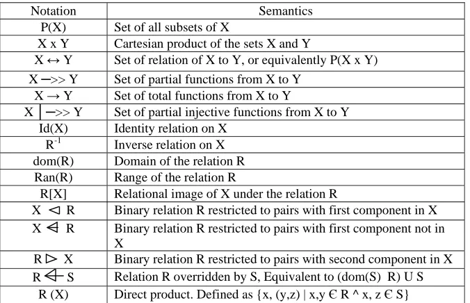
Table 2. Commonly used B operators
Notation Semantics P(X) Set of all subsets of X
X x Y Cartesian product of the sets X and Y
X ↔ Y Set of relation of X to Y, or equivalently P(X x Y) X ─>> Y Set of partial functions from X to Y
X → Y Set of total functions from X to Y
X │─>> Y Set of partial injective functions from X to Y Id(X) Identity relation on X
R-1 Inverse relation on X dom(R) Domain of the relation R Ran(R) Range of the relation R
R[X] Relational image of X under the relation R
X R Binary relation R restricted to pairs with first component in X X R Binary relation R restricted to pairs with first component not in
X
R X Binary relation R restricted to pairs with second component in X R S Relation R overridden by S, Equivalent to (dom(S) R) U S
MACHINE M SEES
Abstract machine referred to here can be accessed as read-only SETS
Sets are introduced by names and optional enumeration of their values CONSTANTS
Constants that can be referred to as read-only PROPERTIES
Define the properties of sets and constants VARIABLES
Variables’ definition INVARIANT
Types of variables and constraints on values INITIALISATION
Assign initial values to variables OPERATIONS
Define machine operations END
Fig. 1. B machine structure
A survey of available tools based on the B method can be found in [17]. Briefly we can say that there are currently two commercially available toolkits that support the complete development of systems using the method, Atelier B from ClearSy [18], and B-Toolkit from B-Core. In this work we chose to use the Atelier B toolkit which allows automatically typing check and verifying the syntax of a specification as well as generating the proof obligations that once discharged guarantees its consistency. To discharge these proof obligations Atelier B provides a theorem prover which can be run either in automatic or interactive mode. The B method is suitable for the development of safety critical systems. It has been successfully applied in large industrial projects as the Meteor automated subway in Paris [19] and the IBM Customer Information Control System (CICS) [20].
4. Simplified fight control system 4.1. Informal specification
The considered flight control system consists of three redundant functions. The system produces periodic signals to the flaps. The system is an asynchronous distributed system, where each function is running on a separate computing device running with its own clock. There is no synchronization between the three clocks. The communication is handled through command messages sent and received over communication channels between the devices.
A master function FR is initially in command until it becomes faulty, it is a periodic function with a period of 20 ms, and is executed on a computing device CR which exists in the right wing. FR produces its commands on the digital channel, wing_channel, placed inside the wings of the plane. The second function is the FL which is an emergency function running on a computing device placed in the left wing and sends its commands also on the wing_channel. It has a period of 20 ms. FL starts to work when FR becomes faulty this is detected by FL when no commands are received from FR for two consecutive cycles. Another secondary emergency function FB is executed on the computing device existing in the body of the plane, it starts to send commands when both FR and FL are faulty. FR and FL are considered faulty if no commands are received during 5 cycles (100 ms). FB sends its commands on the body_channel that is connected to the wing_channel through a bridge.
Figure 3 shows the timed automata representing the function FR running on the device placed in the right wing. The operation starts with a ready state with clock signal reset, then the function either fails and goes to failR state or starts sending command messages through the channels. The time required for sending messages is 20 ms so the function goes back to the ready state after this time passes and the clock is reset. Whenever the function is faulty no messages are received on the communication channels.
Clock skewing, process fluctuations, and differences in the execution times can all be dealt with as communication delays [13], accordingly the asynchronous nature of this system can be represented as communication delays between the three functions.
Communication delay between FR and FL is between 0 and 20 ms, while the communication delays between FB, and FR or FL ranges from 0 to 40 ms.
Two properties of the system are to be proved and verified: Only one function is in command mode at any given time.
Whatever the number of faulty functions, the flaps should not stay without command for more than 160 ms.
Fig. 3. Timed Automata for the function FR running on the device placed in the right wing
4.2. Modeling of the flight control system using B-Method
The system is modeled as 7 B machines. Each function and each communication channel is modeled as a machine describing its local operations and invariants. A root machine is modeling the overall system and describes the global operations and the global invariants.
The properties that need to be verified are included in the INVARIANT clause of a B machine. A model cannot be proved if the properties enclosed in this clause were not respected after the initialization of the machine variables and after each operation call. The proof process is a way to check the global consistency of the mathematical model associated to each B machine. The B tool [20] generates the proof obligations (POs) of the specification according to the mathematical model. A theorem prover is provided to discharge automatically the POs and an interactive theorem prover allows the user to intervene in the proof, when it becomes too complex for the automatic prover.
The machines representing each of the three functions FR, FL, FB model contain:
The definition of a set of local variables representing the clock, and the states of the model. The variables initialization.
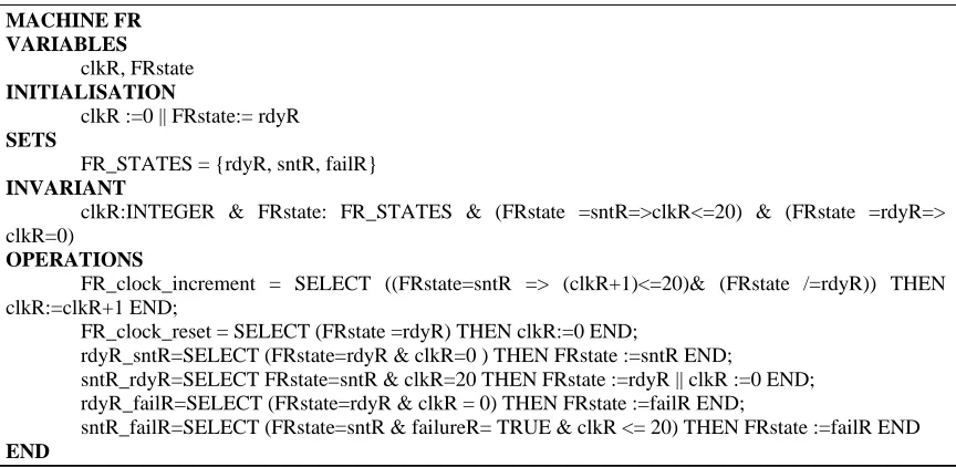
MACHINE FR VARIABLES
clkR, FRstate INITIALISATION
clkR :=0 || FRstate:= rdyR SETS
FR_STATES = {rdyR, sntR, failR} INVARIANT
clkR:INTEGER & FRstate: FR_STATES & (FRstate =sntR=>clkR<=20) & (FRstate =rdyR=> clkR=0)
OPERATIONS
FR_clock_increment = SELECT ((FRstate=sntR => (clkR+1)<=20)& (FRstate /=rdyR)) THEN clkR:=clkR+1 END;
FR_clock_reset = SELECT (FRstate =rdyR) THEN clkR:=0 END;
rdyR_sntR=SELECT (FRstate=rdyR & clkR=0 ) THEN FRstate :=sntR END;
sntR_rdyR=SELECT FRstate=sntR & clkR=20 THEN FRstate :=rdyR || clkR :=0 END; rdyR_failR=SELECT (FRstate=rdyR & clkR = 0) THEN FRstate :=failR END;
sntR_failR=SELECT (FRstate=sntR & failureR= TRUE & clkR <= 20) THEN FRstate :=failR END END
Fig. 4. B machine for the function running on the device placed in the right wing
Figure 3 shows the B machine describing the function running in the right wing. It starts by the machine name FR, and then the local variables are defined to be the clock clkR and the states of the function FR FRstate. The INITIALIZATION clause is used to set the initial value of the clock to 0, and the initial state of the function to ready.
The SETS clause then defines that the function FR can be in one of three states rdyR, sntR, or failR.
The INVARIANT clause indicates the constraints that must be respected, the first constraint is the type of the clock signal which must be an integer value, and that of the FRstate must be one of the defined FR_STATES. Also whenever the FR function is in the sending state the clock value should be less than 20 which is the value of the time required for sending a message over the channels. The last invariant is that the clock should be reset to zero when the FR function is in the ready state before sending messages.
The OPERATION clause describes the increment and reset of the clock signals and the transitions between states. The clock is incremented while sending command messages (FR is in the sntR state) and till it reaches a maximum value of 20. The clock is reset when the function is ready for sending messages (rdyR state). The transition from the ready state to start sending messages is described by the operation rdyR_sntR. The function goes back to the ready state after 20 ms passed and the clock signal is reset (sntR_rdyR). A transition to a failR state is possible from either the ready or sending message state to represent failure in the function (rdyR_failR, sntR_failR ).
Similar B machines are used to describe the functions running in the left wing and in the body of the plane.
Another 3 B machines are used to formally describe the communication channels between the function FR, FL, FB.
Each channel has two states indicating a message is passing through the channel or not.
The root machine describes all the interaction between the function and channel machines, global variables are defined indicating the sending and receiving of messages from and to the three functions across the communication channels.
Invariants in the root machine describe the communication delays and restrict the values of the global variables in different states.
The invariants clause in the root machine also includes the two main properties of the system that needs to be verified;
Only one function is in command mode at any given time, an invariant is used to restrict the state of the three functions so that only one of them is in the snt state.
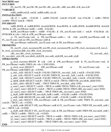
MACHINE root INCLUDES
FL_inst.FL, FR_inst.FR, FB_inst.FB, cRL_inst.cRL, cRB_inst.cRB, cLB_inst.cLB VARIABLE
rmRL,rmRB,rmLB, smLB, smRB,smRL,sm,clk INITIALISATION
clk:=0 || smRL :=FALSE || smRB:=FALSE ||smLB:=FALSE ||sm:=FALSE || rmRL:=TRUE ||rmRB:=TRUE ||rmLB :=TRUE
INVARIANT
smRL:BOOL & smRB:BOOL &smLB:BOOL &sm:BOOL & rmRL:BOOL &rmRB:BOOL &rmLB :BOOL & (FR_inst.FRstate=failR=> rmRL =FALSE)
&(FR_inst.FRstate=failR=> rmRB =FALSE) & (FL_inst.FLstate=failL=> rmLB =FALSE)& clk: INTEGER & (clk<=160) & ((FR_inst.FRstate=sntR
or FL_inst.FLstate=sntL or FB_inst.FBstate=sntB)=> clk =0)& not((FR_inst.FRstate=sntR & FL_inst.FLstate=sntL)or (FR_inst.FRstate=sntR &
FB_inst.FBstate=sntB)or(FL_inst.FLstate=sntL & FB_inst.FBstate=sntB)) PROMOTES
FL_inst.FL_clock_increment,FR_inst.FR_clock_increment,FB_inst.FB_clock_increment,cLB_inst.cL B_clock_increment,cRB_inst.cRB_clock_increment,
cRL_inst.cRL_clock_increment, FL_inst.sntL_rdyL, FL_inst.idleL_rdyL,FB_inst.idleB_rdyB,FB_inst.sntB_rdyB,FR_inst.sntR_rdyR
OPERATIONS
g_clock_incremet=BEGIN IF (clk <160 & (FR_inst.FRstate/=sntR & FL_inst.FLstate/=sntL & FB_inst.FBstate/=sntB)) THEN clk:=clk+1 END END;
g_clock_reset=SELECT (FR_inst.FRstate=sntR or FL_inst.FLstate=sntL or FB_inst.FBstate=sntB)THEN clk :=0 END;
g_rdyL_failL=SELECT (smLB= FALSE) THEN FL_inst.rdyL_failL || rmLB :=FALSE END; g_sntL_failL=SELECT (smLB= FALSE) THEN FL_inst.sntL_failL || rmLB :=FALSE END; g_idleL_failL=SELECT (smLB= FALSE) THEN FL_inst.idleL_failL || rmLB :=FALSE END; g_idleB_idleB=SELECT (rmLB = TRUE or rmLB =TRUE) THEN FB_inst.idleB_idleB END ; g_idleL_idleL=SELECT rmRL = TRUE THEN FL_inst.idleL_idleL END;
g_state2_state1=SELECT ( rmLB = TRUE or rmRB=TRUE) THEN cLB_inst.state2_state1 END; g1_state2_state1=SELECT ( rmLB = TRUE or rmRB=TRUE) THEN cRB_inst.state2_state1 END; g2_state2_state1=SELECT rmRL = TRUE THEN cRL_inst.state2_state1 END;
g_rdyR_failR=BEGIN FR_inst.rdyR_failR || rmRL :=FALSE || rmRB :=FALSE END; g_sntR_failR=BEGIN FR_inst.sntR_failR || rmRL :=FALSE || rmRB :=FALSE END;
g_rdyL_sntL=SELECT (FR_inst.FRstate/=sntR & FB_inst.FBstate/=sntB) THEN FL_inst.rdyL_sntL ||smLB:= TRUE || clk :=0 END;
g_rdyB_sntB=SELECT (FR_inst.FRstate/=sntR & FL_inst.FLstate/=sntL) THEN FB_inst.rdyB_sntB || sm := TRUE || clk :=0 END;
g_rdyR_sntR=SELECT (FL_inst.FLstate/=sntL & FB_inst.FBstate/=sntB) THEN FR_inst.rdyR_sntR || smRL := TRUE || smRB:= TRUE || clk :=0 END;
g1_state1_state2=SELECT (smLB = TRUE or smRB = TRUE) THEN cLB_inst.state1_state2 END ; g2_state1_state2=SELECT (smLB = TRUE or smRB = TRUE) THEN cRB_inst.state1_state2 END ; g3_state1_state2=SELECT smRL = TRUE THEN cRL_inst.state1_state2 END
END
Fig. 5. B machine for the root model
Figure 5 shows the B machine describing the root or the global control system, where the INCLUDE clause states all the 6 B machines that are included in the system that represents the functions and the communication channels.
Then the VARIABLES clause defines the global system variables which are the rmRL, rmRB to indicate command messages are received from the function FR to the other two functions, rmLB to indicate messages are received from the FL function and it is not faulty. smRB and smRL are used to to indicate FR is sending messages smLB, to indicate FL is sending messages sm is used to indicate the FB function is sending messages, clk is the global clock signal.
The INVARIANT clause restricts the type of each variable, then describes the constraints on each of the variables in different states of the three functions. Also the properties the system must satisfy are described (clk<=160), and Only one function is in command mode at any given time ( not((FR_inst.FRstate=sntR & FL_inst.FLstate=sntL)or (FR_inst.FRstate=sntR & FB_inst.FBstate=sntB)or(FL_inst.FLstate=sntL & FB_inst.FBstate=sntB))
Local function in the individual machines are called in the PROMOTE clause to be used in the global operations.
The OPERATIONS clause starts to describe all the global transitions. The clock increment and reset are described by g_clock_incremet and g_clock_reset.
The operation (g_rdyR_sntR=SELECT (FL_inst.FLstate/=sntL & FB_inst.FBstate/=sntB) THEN FR_inst.rdyR_sntR || smRL := TRUE || smRB:= TRUE || clk :=0 END; ) states that when the two functions FL and FB are not in the sending messages state the FR goes from the ready state to start sending messages(the local operation rdyR_sntR is called) and the two global variables smRL and smRB are set to TRUE and the global clock is reset.
The operation (g_rdyR_failR=BEGIN FR_inst.rdyR_failR || rmRL :=FALSE || rmRB :=FALSE END;) describes that when FR goes to be faulty the local operation rdyR_failR is called and the two global variables rmRL and rmRB are set to FALSE.
The operation (g_sntR_failR=BEGIN FR_inst.sntR_failR || rmRL :=FALSE || rmRB :=FALSE END;) describes the case when FR becomes faulty while sending command message, in this case the local operation sntR_failR is called and the global variables rmRL and rmRB are set to FALSE to indicate the function is faulty.
Similarly the operations describes the transitions between states, calls local operations, and set the values of the global variables.
5. Results and Discussion
Distributed computing systems are generally composed of a group of communicating processes. This work considers the asynchronous behavior of the distributed system and shows how to verify functional and real time properties. Modeling the asynchronous behavior of the system was not an easy job. It was required to check that the three functions running on separate devices in the wings and body of the plane satisfy an overall timing constraint and to prove that only one is sending command messages at a time. Global variables for sending and receiving messages were used to model the communication between the asynchronous functions. Also signals on the communication channels were used to detect the faulty functions. Each function was modeled as a separate B machine and verified where timing and local variable constraints generated proof obligations that were successfully verified like the values of the local clock in each state of the function. Also communication channels were modeled and verified separately where all clock skews were modeled as communication delays. Then the overall system was described and the overall behavior of the system was verified to check the timing constraints and behavioral properties were satisfied in all system states.
Atelier B tool [20] was used for modeling and verification using B method. Atelier B provides an interactive prover where the designer can read and edit the proof obligations extracted from the model to match the system specifications.
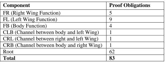
Table 3 gives a summary of the formal proof of the specification. The proof obligations arise in proving that the Abstract Machine operation does not violate an invariant.
6. Conclusion and Future Work
Table 3. Number of POs for each component
Component Proof Obligations
FR (Right Wing Function) 5 FL (Left Wing Function) 9
FB (Body Function) 4
CLB (Channel between body and left Wing) 1 CRL (Channel between right and left Wing) 1 CRB (Channel between body and right Wing) 1
Root 62 Total 83
References
[1] Campos, J. C., Machado, J., and Seabra, E. (2008), “Property patterns for the formal verification of automated production systems”,
IFAC 08, pp. 5107-5112.
[2] Michael C. McFarland. (1993), “Formal Verification of Sequential Hardware: A Tutorial” IEEE Transcations on Computer-Aided
Design of Integrated circuits and systems, 12(5) pp. 633 - 654.
[3] Roussel, J.-M. and Denis, B. (2002), “Safety properties verification of ladder diagram programs”, Journal Europeen des Systemes
Automatisees, 36 pp. 905-917.
[4] Smet, O. D. and Rossi, O. (2002), “Verification of a controller for a flexible manufacturing line written in ladder diagram via model-checking”, 21th American Control Conference, ACC'02, pp. 4147-4152.
[5] Rossi, O. (2003), “Validation formelle de programmes ladder pour automates programmables industriels”, PhD thesis, Ecole Normale
Supérieure de Cachan, France.
[6] Gaid, M., B_erard, B., and Smet, O. (2005), “Verification of an evaporator system with uppaal”, European Journal of Automated
Systems, 39(9) pp. 1079-1098.
[7] Machado, J., Denis, B., and Lesage, J.-J. (2006). “A generic approach to build plant models for des verification purposes”, 8th
International Workshop On Discrete Event Systems (WODES'06), pp. 407-412.
[8] J. Bengtsson, W. O. D. Griffoen, K. J. Kristoffersen, K. G. Larsen, F. Larsson, P. Pettersson, and Y. Wang ( 1996), “Verification of an audio protocol with bus collision using UPPAAL”, Lecture Notes in Computer Science, Computer Aided Verification. Heidelberg, Germany: Springer-Verlag, vol. 1102, pp. 244-256.
[9] J. Romijn (1999), “A timed verification of the IEEE 1394 leader election protocol”, 4th Int. ERCIM Workshop Formal Methods for
Industrial Critical Systems (FMICS’99), pp. 3-29.
[10] D. P. L. Simons and M. I. A. Stoelinga (2000), “Mechanical verification of the tree 1394a root contention protocol using uppaal2k”,
Comput. Sci. Inst. Nijmegen, Nijmegen, the Netherlands, Tech. Rep. CSIR0009.
[11] T. Stauner, O. Müller, and M. Fuchs (1997), “Using HyTech to verify an automotive control system”, Lecture Notes in Computer
Science, Hybrid and Real-Time Systems. Heidelberg, Germany: Springer- Verlag, vol. 1201, pp. 139-153.
[12] T. Ball, B. Cook, V. Levin, and S. K. Rajamani (2004), “SLAM and static driver verifier: technology transfer of formal methods inside Microsoft”, Integrated Formal Methods Conf., Canterbury, U.K. pp.5-19.
[13] Ayman M. Wahba (2007), “Discrete versus continous models in the verification of real time distributed systems using formal
methods”, CSE Department, Faculty of Engineering, Ain Shams University. Scientific Bulletin, vol 42, No.3.
[14] Anaheed Ayoub, Ayman M. Wahba, M. Sheirah (2010), “Analyzing safety-critical real-time systems”, PhD. Thesis, Faculty of
Engineerin, Ain Shams University, Egypt
[15] Abrial, J.R. (1996): “The B Book - Assigning Programs to Meanings”, Cambridge University Press.
[16] Dijkstra, E.W. (1976): “A Discipline of Programming”, Prentice-Hall, Upper Saddle River, NJ, USA.
[17] Site B Grenoble. http://www-lsr.imag.fr/B/b-tools.html.
[18] http://www.atelierb.eu/index-en.php, “Atelier B, the industrial tool to efficiently deploy the B Method”.
[19] Behm, P., Benoit, P., Faivre, A., Meynadier, J.M.: METEOR (1999), “A successful application of B in a large project”, FM'99: World
Congress on Formal Methods, pp. 369-387.
[20] Hoare, J., Dick, J., Neilson, D., Sorensen, I. (1996), “Applying the B technologies to CICS”, FME '96: Industrial Benefit and