Design and Development Model of Spiral Bevel Gear
with Minimized Weight
1
Nitin Hari Chaudhari,
2Dr. D. N. Kamble
1
PG Student,2Professor 1
Department of Mechanical Engineering, 1
Sinhgad Academy of Engineering Kondhawa (BK) , Pune,India
_________________________________________________________________________________________ _______________
Abstract—This paper, the spiral be vel gear (SBG) is a key component of the power transmission of non-par al lel shafts.Consi dering example such as hand hel d tool wood working mac hines, these machines are use d to c ut the wood work-piece for the making furni ture, Casting pattern, woode n seat design, wood prototyping etc . In that mac hine the set of spiral be vel gears used for power transmission from motor to tool. The hand hel d tools weight and continues vi br ati ons makes it difficult to oper ate the machine for longer ti me and also power c onsumption per unit cut has bee n ver y high , and vi brations lead to inaccur acy in cutting and error in pr ofile shape. Thus methodology used in study is to carry out test on three sets of be vel firstly plain gears (i.e . no weight re duction), secondl y weight re duc tion done by face counter and thirdl y by pr ovi di ng equi distance holes on the face. The de vel opme nt of spiral be vel gear we can re duce weight, material, pr oc ess timing and c ost of produc tion.Compar ati ve the perfor mance analysis of the gears by l oad so as to deri ve the opti mal per for mance of the gears .
IndexTerms—Weight reduction, Face recess, Face holes, optimal perfor mance characteristic.
________________________________________________________________________________________________________
I. IN TRO DUC TION
The gear is use as a mechanical devicein transmission systems it allows to transfer the rotational force to another gear or device. The gear teeth, or cogs, allow force to be fully transmitted without slippage and depending on their configuration, can trans mit forces at different speeds, torques, and even in a different direction. Throughout the mechan ical industry, many types of gears exist with each type of gear possessing specific benefits for its intended applications.Mostly bevel gears are used for powertransmission between nonparallel shafts at almost any angle or speedbecause of their suitability. Spira l bevel gears have curved and sloped gear teeth in relation to the surface of the pitch cone. As a result, an oblique surface is formed during gear mesh which allows c ontact to begin at one end of the tooth (toe) and smoothly progress to the other end of the tooth (heel).
II.PROCEDURE
A. Topol ogy optimization
Topology optimization of continuum structures is most challenging technically and rewarding economically. Rather than limit ing the changes in the sizes of structural components, topology optimization provides much more freedom and allows to designer to create totally novel and highly efficient conceptual design for continuum structures. The stress level in all par t of a structure can be determined by using a finite element analysis. The reliable indicator of inefficient use of materia l is low values of stress (or strain) in some parts of the structure. Ideally the stress in all part of the structure should be close to the same or safe le vel. This concept leads to the rejection criterion based on local stress. Where the low-stressed materia l is assumed to be under-utilized and is therefore eliminated subsequently. The removal of materia l can be conveniently undertaken by removing ele ments from th e finite e le ment model.
Topology optimizat ion method has been used to optimize the structure of the gear. The minimu m volu me was set as the direct optimization goal. The topology optimizat ion can provide designers with a conceptual design at the initial stage of a structu ral design, thus it improve the design efficiency, design quality, and reduce the development costs.
B. Proble m State ment
The weight of the hand held tools and subsequent vibrations makes it difficult to operate the machine for longer time and als o high power consumption, and vibrations lead to in accuracy in profile cutting and error in shape.
Thus it required study is to carry out test on three sets of bevel gears namely plain (i.e. no weight reduction), secondly weight reduction done by providing recess on the face of gear , an thirdly by providing even number and equi-spaced holes on the face.
C. Objecti ve
Effect of we ight reduction on vibration of gear through experimentation validation.
III.VIBRATION ANALYS IS-THEORETICALLY
a) Drilling the given profile hole size into the material: This process consumes ma ximu m power and accounts for ma ximu m vibration.
b) Milling process involves the lateral movement of tool with reference to the work-piece to achieve the desired length of cut, this process accounts for lesser power consumption as compared to drilling process hence accounts to lesser vibration.
Thus the plunge drilling operation characteristic are used to determine the power requirements to account for ma ximu m factor of safety.
Thus the analogy of drilling a ma ximu m size of hole i.e . 12mm in alu minum a lloy material.
Thus mo ment required by the machine to perform drilling operation on the given profile is given by following relations: A) MOMENT (M) = Hb x D2 x f / 8
Here material to be machined is alu minu m a lloy where Hb = 95 kgf/ mm2 for alu minu m alloy
D= d ia meter of drill = 12 mm F= in feed = 0.005 mm/ rev
Hence M = 95 x 12 2x 0.05 / 8 = 10.68 kgf – mm = 106.8 N-mm M= 0.106.8 N-m
Thrust developed during the metal cutting operation is given by T = 1.7 TO 3.5 (M/d) = 1.7 X (0.106 X 103/ 12) = 15.016N T = 15 N =1.52 kg
This is the ma ximu m force that is acting on the cutter in router operation vertically upward direction lading to vibration which needs to be damped by the damper.
Thus the loading of the system developed using a load dynamometer will carry load of 1.5 kg to 2.5 kg as in 1.5 kg, 1.8 kg, 2.0 kg, 2.3kg, 2.5kg, this is to check the frequency response of the system under various loading condition i.e. , 100% loading to 160% loading thereby ensuring the safe operation of the system for a llo wable acceleration in device not to exceed 7.7 m/sec2.
The oretical Calculati on for Displace ment and acceleration- Power input = 350 watt
Maximu m accele ration = 7.7 m/sec2 Angular speed (ω) = 2 π N/ 60 (ω) = 2 π x 3000 / 60 =314.16 rad/sec
Let F0=Force transmitted to machine handle / foundation F0= m0 e ω2
(m0 e) = Rotating imba lance owing to the dynamometer pulley action = (1.5 x 0.1/2) = 0.075 kg-m
Thus; F0= m0 e ω2 F0= 0.075 x 314.22 F0=7.4x10³ N
Considering the ma ximu m transmitted ratio as ; T = FT / F0
The ma ximu m permissible a mplitude of force transmitted not to exceed 3500 N T = 3500 / 7.4 x10³
T= 0.47
Now as T<1 , T = 1/( r2-1)
r = Sq. rt (1 +1/ 0.47 ) = 1.76
Now,
Natural frequency (ωn) = ω /r (ωn) = 314.2/ 1.76 = 178.5 rad /sec
Now Equivalent stiffness of the system is given by, Keq = m ωn2
Keq = 1.5 x 1178.52 Ke q = 47.7x10³ N/m
δ = (1.5) X 9.81 / 47.7 = 0.308 mm
Thus maximu m displacement of the system δ =0.308 mm δ =0.308mm---rounded off to o.3 mm
The oretical deter mination of acceleration under give n system of forces: Ft = kx + c x
Cx = Ft – kx=(1.5) – (47.7/9.81 x 0.3) =0.04 C= 0.04 / x = 0.04 /0.3 =0.133
If the base of the system is subject to displacement y(t)., then the acceleration transmitted to the machine of mass m is determined as
ǟ = (c z + k z) / m Where
ǟ = acceleration transmitted to the machine m/sec2
z = displacement of the machine relative to its base and is equal to the total displacement of the isolator. Ǟ = 0.133X 0.3 +4.77 X 0.3 = 1.471m/sec2
Thus ma ximu m acceleration of the machine at no load condition is 147.1 m m/sec2
As the actual acceleration as effect of load of 1.5 kg on dynamometer pulley is 1.47m/sec2 < allowable 7.7 m/sec2 the system is safe for use in hand tools as the ma ximu m accelerations well within control.
IV.EXPERIMENTATION
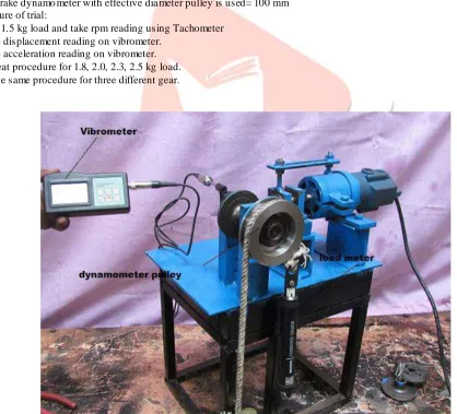
Rope brake dynamo meter with effective dia meter pulley is used= 100 mm Procedure of trial:
1. Add 1.5 kg load and take rpm reading using Tachometer 2. Note displacement reading on vibrometer.
3. Note acceleration reading on vibrometer. 4. Repeat procedure for 1.8, 2.0, 2.3, 2.5 kg load. 5. above same procedure for three different gear.
A. Plain Bevel Gear B. With hole C. Face Counter reduction
V.TEST AND RESULT
A. On plain spiral bevel gear
Result table for theoretical d isplacement and accelerat ion
Sr . no
Load (kg)
The oretical Experi mental
Displacement (mm)
Acceleration (m/sec2)
Displacement (mm)
Acceleration (m/sec2)
1 1.5 0.30958 1.47 0.31 1.6
2 1.8 0.37150 1.835 0.39 1.9
3 2.0 0.41277 2.034 0.44 2.24
4 2.3 0.47469 2.315 0.49 2.46
5 2.5 0.51597 2.56 0.53 2.69
B. On plain spiral bevel gear –with hole reduction
Result table for theoretical d isplacement and accelerat ion
Sr . no
Load (kg)
The oretical Experi mental
Displacement (mm)
Acceleration (m/sec2)
Displacement (mm)
Acceleration (m/sec2)
1 1.5 0.30958 1.47 0.34 1.85
2 1.8 0.37150 1.83 0.41 2.25
3 2.0 0.41277 2.03 0.46 2.43
4 2.3 0.47469 2.31 0.51 2.79
5 2.5 0.51597 2.56 0.59 3.02
Gr aph 3. Load vs. Displace mentGr aph 4. Load vs Acceleration
C. On spiral bevel gear –with face counter reduction
Result table for theoretical d isplacement and accelerat ion
Sr. no
Load (kg)
The oretical Experi mental
Displacement (mm)
Acceleration (m/sec2)
Displacement (mm)
Acceleration (m/sec2)
1 1.5 0.30958 1.47 0.347 1.95
2 1.8 0.37150 1.83 0.44 2.45
3 2.0 0.41277 2.03 0.49 2.63
4 2.3 0.47469 2.31 0.59 2.94
Gr aph 5. Load vs Displacement GraphGraph 6. Load vs. Acceleration
VI.CONCLUS ION
Maximu m accele ration in case of the bevel gear with face reduction is 3.22 m/sec2 which is slightly higher as compared to ( 3.02 of bevel gear with hole reduction and 2.69 with plain bevel gear) …thus the bevel gear with face counter reduction can b e recommended over other two gears.
Maximu m weight reduction is achieved by face counter reduction 14.15 %.3. Maximu m stress in all conditions is well below the allowable limit hence weight reduction by either methods is recommended Weight reduction by the face counter method is recommended as it offers minima l deformation and only marg inal increased stress as compared to the hole reduction method.
VII. AC KNOWLEDGMEN T
My profound thanks to my guide Prof. D. N. Ka mb le sir, I a m thankful to Prof. Dr. S. S. Kore sir Head of Department of Mechanical Engineering for his invaluable advice and constant encouragement to complete this Paper in a successful manner.
I a m thankful to our ME coordinator Prof. S R Patil sir for his kind support and providing all facilities and academic environment for my Research paper work.
REFER ENC ES
1. Sekerc ioglu, T., Kovan, V. (2007). Pitting fa ilure of truc k spiral bevel gear. Engineering Failure Analysis, vol. 14, no. 4, p. 614-619, DOI:10.1016/ j.engfailanal.2006.03.002.
2. Polubinski, J., Ali, A. (2010). Simu lation analysis of commerc ial t ruck spira l bevel gear process.International Journal of Modelling in Operat ionsManagement, vol. 1, no. 2, p. 179 -208, DOI:10.1504/IJM OM.2010.038149.
3. Le wic ki, D.G., Handschuh, R.F., Henry, Z.S., Litvin, F.L. (1994). Low-noise, High-strength, spiral bevel gears for helicopter transmissions. Journal of Propulsion and Power, vol. 10, no. 3, p. 356-361, DOI:10.2514/3.23764.
4. Handschuh, R.F., Bibel, G.D. (1999). Expe rimental and analytica l study of ae rospace spiral bevel gear tooth fillet stresses. Journal of Mechanical Design, vol. 121, no. 4, p. 565-572, DOI:10.1115/ 1.2829500.
5. Fong, Z.H., Tsay, B.C.B. (1991). A study on the tooth geometry and cutting machine mechanisms of spiral bevel gears. Journal of Mechanical Design, vol. 113,no. 3, p. 346-351, DOI:10.1115/1.2912788.
6. Xing, Y., Qin, S.F., Wang, T.Y., Cheng, K. (2011). Subdivision surface modeling fo r spira l bevel gear manufacturing. International Journal of Advanced Manufacturing Technology, vol. 53, no. 1-4, p. 63-70,DOI:10.1007/s00170-010-2813-1.
7. Ra mg ir M.S,” Achieving mass reduction in the spur gear using topology optimization for design evaluation and analysis” International Journal of Sc ientific Research and Management Studies, ISSN: 23493771 Vo lu me 1Issue 8, pg: 270-274.(2012).
8. Márklelkes, Danie l play and Jánosmaria ligeti, “cutting parameters definit ion for kine mat ic optimizat ion of spiral bevel gears,” periodica polytechnic ser.transp.Eng. VOL. 30, NO. 1–2, PP. 93–109 (2010).
9. Frit z Kloc kea, Markus Bru mma,” Influence of Gear Design on Tool Load in Bevel Gear Cutting”, sciencedirect,Proce dia