IJEDR1704131
International Journal of Engineering Development and Research (
www.ijedr.org
)
796
A Survey on Different types of Flexible AC
Transmission Systems (FACTS) Controllers
Naseeb Khatoon 1 & Sajida Shaik 2
1Electrical and Electronics Engineering, Telangana, India 2Electrical and Electronics Engineering, Andhra Pradesh, India
________________________________________________________________________________________________________
Abstract - In the last two decades, power demand has increased substantially while the expansion of power generation and transmission has been severely limited due to limited resources and environmental restrictions. As a consequence, some transmission lines are heavily loaded and the system stability becomes a power transfer-limiting factor. Flexible AC transmission systems (FACTS) controllers have been mainly used for solving various power system steady state control problems. For the development and improvement of dynamic performance of the modern power system, Flexible AC Transmission Systems (FACTS) devices have been used since 1970s. A Flexible Alternating Current Transmission System (FACTS) is a system composed of static equipment used for the AC transmission of electrical energy. FACTS devices use power electronic components to improve system performance. FACTS controller includes Fixed Capacitor Thyristor Controlled Reactor (FC_TCR), Static Synchronous Compensator (STATCOM), Thyristor Controlled Series Compensator (TCSC), Static Series Synchronous Compensator (SSSC), Static VAR Compensator (SVC), Unified Power Flow Controller (UPFC), Hybrid Flow Controller (HFC), Rotary Hybrid Flow Controller (RHFC), Amalgam Power Flow Controller (APFC) which are used in the transmission and distribution system to improve power transfer capability and to enhance power system stability. In this paper review on different types of FACTS controller has been discussed and also a new device of FACTS family named as amalgam power flow controller (APFC) is introduced and also gives idea regarding various applications of FACTS controllers.
Keywords -FlexibleACTransmissionSystem(FACTS), FACTSControllers, GUPFC, HPFC, IPFC, SVC, SSSC, STATCOM, DSTATCOM, TCSC, TCPAR, TCR, TSR, TSSC, TCSR, TSSR, UPFC, PST, APFC.
________________________________________________________________________________________________________
I.
IntroductionToday power systems are highly complex and require careful design of new devices taking into consideration the already existing equipment especially for the transmission systems in a new deregulated electricity markets. In the late 1980s the EPRI (electric power research institute) introduced a new approach to solve the problem of designing and operating power system the proposed concept is known as flexible AC transmission systems (facts).The two main objectives of FACTS is to increase the transmission capacity and control the power flow over designated transmission routes.
IJEDR1704131
International Journal of Engineering Development and Research (
www.ijedr.org
)
797
magnitude at generator terminals, as well as sources or sinks of reactive power, such as shunt capacitors (SCs), shunt reactors (SRs), rotating synchronous condensers (RSCs) and SVC. SCs and SRs are either permanently connected to the power system or can be switched on and off according to operative conditions. Nevertheless, they provide passive compensation since their production or absorption of reactive power depends on their rating and the bus voltage level at which they are connected. On the other hand, the reactive power absorbed/supplied by RSCs and SVCs is automatically adjusted so as to maintain fixed voltage magnitude at connection points. Load-tap changing transformers (LTCs) whose main function is to regulate volt-age magnitude at its terminals by changing their transformation ratio. Advances in power electronic technologies together with sophisticated electronic control methods made possible the development of fast static compensators namely Flexible AC Transmission Systems (FACTS).The FACTS technology has become one of the most valuable compensation techniques, because it applies the latest advances in power electronics to achieve additional and more effective control of the parameters of the electrical systems. This rep-resents the most efficient combination of conventional primary equipment, high power semiconductor devices, microelectronics and telecommunications equipment, allowing a most flexible power electric system. The main operational objective of both FACTS devices is to increase power transmission capability by voltage control at the point of connection of the power network.So for better utilization of available or present power system, flexible AC transmission systems (FACTS) controllers have been implemented. With the help of multiple FACTS controllers, we can easily control various parameters of transmission line such as line impedance, terminal voltage, and voltage angles.
II.
Flexible Alternating Current Transmission System (FACTS)Flexible Alternating Current Transmission System (FACTS) is static equipment used for the AC transmission of electrical energy. It is meant to enhance controllability and increase power transfer capability. It is generally power electronics based device. The FACTS devices can be divided in three groups, dependent on their switching technology:
• Mechanically switched (such as phase shifting transformers), • Thyristor switched or fast switched,
• Thyristor switched or fast switched using IGBTs.
While some types of FACTS, such as the phase shifting transformer (PST) and the static VAR compensator (SVC) are already well known and used in power systems, new developments in power electronics and control have extended the application range of FACTS. Furthermore, intermittent renewable energy sources and increasing international power flows provide new applications for FACTS. The additional flexibility and controllability of FACTS allow to mitigate the problems associated with the unreliable of supply issues of renewable. SVCs and STATCOM devices are well suited to provide ancillary services (such as voltage control) to the grid and fault rid through capabilities which standard wind farms cannot provide Furthermore, FACTS reduce oscillations in the grid, which is especially interesting when dealing with the stochastic behavior of renewable.
A.
Definition Of FactsAccording to IEEE, FACTS, which is the abbreviation of Flexible AC Transmission Systems, is defined as follows “Alternating current transmission systems incorporating power electronics based and other static controllers to enhance controllability and PTC”.
B.
Benefits For FACTS ControllersSome of important possible benefits for FACTS controllers in restructure multi-machine power system Environments are listed below [2].
• The flow of power within the existing power system can be maintained as per the contract or as per the demand of the utilities.
• Secure loading of transmission lines nearer to their thermal limits. • Increased dynamic and transient grid stability.
• Allows more active power in present lines by reducing reactive power flow in the line. • Access to lower production cost.
• Environmental benefits. • Upgrade of transmission lines.
• Reduce RP flows, thus allowing the lines to carry more active power. • Loop flow control.
• FACTS gadgets furnishes secure tie line connection with neighboring utilities by diminishing generally speaking crop save prerequisites on either sides.
• Operation speed of whole power system get improved with help of FACTS devices. • Interconnection of renewable and distributed generation and storages.
• Power System Stability Improvement Using FACTS Devices
C.
Drawback Of FACTS Technology• It produces large no. of harmonics in the system. • It requires filters.
• More expensive than other conventional devices.
III.
FACTS Controllers Allocation Techniques/MethodsIJEDR1704131
International Journal of Engineering Development and Research (
www.ijedr.org
)
798
considering there different operating conditions viewpoint. References [7], [8], classifies three main techniques for the placement or allocation of FACTS controllers from different operating conditions viewpoint in multi-machine power systems at suitable location, such as a1) Sensitivity Based Method (SBM) 2) Optimization Based Method (OBM) and 3) Artificial Intelligence Techniques(AIT)
The various sensitivity based methods have been proposed in literatures includes jocobian based sensitivity method [9], eigen-value analysis based methods modal analysis techniques , index methods , residue-based methods ] some of other methods are pole placement techniques, frequency response techniques, root locus techniques, projective control method, non-linear feed control method, Lambda iteration method, Eigen-Sensitivity Theory of Augmented Matrix.
The various optimization based methods have been proposed in literatures that include curved space optimization techniques , dynamic optimization programming algorithms, bellman's optimization principle, mixed integer-optimization programming techniques, decomposition coordination methods , hybrid optimization programming algorithms , and non-linear optimization programming techniques, some of other methods are linear optimization programming techniques, immune based optimization algorithms, Mixed-Integer Linear Programming (MILP).
The various artificial intelligence (AI) based methods proposed in literature includes genetic algorithms (GA) , micro- genetic algorithms (MGA) , Tabu Search algorithms or Tabu Search optimization (TSO) ,Simulated Annealing (SA) based approach , graph search algorithms, Particle Swarm Optimization (PSO) techniques, ant colony optimization (ACO) algorithms, Fuzzy Logic (FL) based approach, artificial neural network (ANN) based algorithms, Bacterial Swarming Algorithm (BSA),Bees Algorithm some of other techniques/methods are improved evolutionary programming, non - dominated sorting genetic algorithm II (NSGA-II), Adaptive Hopfield Neural Network, augmented Lagrange multiplier approach, norm forms of diffeomorphism techniques, gravitational optimization techniques, benders decomposition techniques, evolution strategies algorithms, heuristic and algorithmic approach, hybrid meta- heuristic approach, energy approach, adaptive neuro-fuzzy inference system (ANIS) techniques, H-infinity optimization techniques, μ -synthesis techniques, linear matrix inequality technique, prony methods, riccati equations methods, relative gain array (RGA) theory, Adaptive Neuro-Fuzzy Inference Systems (ANFIS).
IV.
A. Conventional Equipment And FACTS ControllersFollowing are the Conventional Equipment and FACTS Controllers For Enhancing Power System Control 1) Conventional Equipment
• Series Capacitor -Controls impedance
• Switched Shunt-Capacitor and Reactor - Controls voltage • Transformer LTC -Controls voltage
• Phase Shifting Transformer -Controls angle • Synchronous Condenser -Controls voltage
• Special Stability Controls-Focuses on voltage control but often include direct control of power
• Others (When Thermal Limits are Involved) - Can included reconductoring, raising conductors, dynamic line monitoring, adding new lines, etc.
2) FACTS Controllers
• Thyristor-controlled voltage limiter (TCVL) • Thyristor Controlled Series Reactor ( TCSR) • Thyristor Controlled Reactor ( TCR) • Thyristor Switched Reactor ( TSR)
• Thyristor-controlled voltage regulator (TCVR)
• Thyristor Controlled Phase Shifting Transformer (TCPST) • Thyristor Controlled series Capacitor(TCSC)
• Thyristor Switched Series Capacitor (TSSC) • Static Synchronous Compensator (STATCOM) • Static VAR Compensator (SVC,TSC,TCR) • Static Synchronous Series Controller (SSSC) • Interline power flow controller (IPFC) • Unified Power Flow Controller (UPFC) • Sen transformer
• Hybrid flow controller (HFC) • Phase Shifting Transformer ( PST)
• Distribution Static Compensator (DSTATCOM) • Generalized Unified Power Flow Controller (GUPFC) • Rotary Hybrid Flow Controller (RHFC)
• Amalgam Power Flow Controller (APFC) B. Generation of Facts Controllers
IJEDR1704131
International Journal of Engineering Development and Research (
www.ijedr.org
)
799
It includes SVC, TCSC and TCPST.2. Second Generation of FACTS Controllers
It includes STATCOM, SSSC, UPFC, and IPFC. 3. Third Generation of FACTS Controllers
It includes GUPFC, HPFC .
4. Fourth Generation of FACTS Controllers
It includes APFC
V.
Connection Of Facts ControllersIn reference the installation of one FACTS devices in the power system does not improve voltage stability and reduction in power system losses so multi-type FACTS devices are used to enhance both voltage stability margin and reduce losses in the system. For the better utilization of existing power system the proper coordination of one FACTS devices or multi-FACTS controller is necessary. The various types of interactions of multi-FACTS controllers are presented in includes,
• Multiple FACTS controllers of a similar kind • Multiple FACTS controllers of a dissimilar kind
• Multiple FACTS controllers and HVDC converter controllers
The various interactions that take place between the different types of FACTS controllers, as well as between FACTS and PSS’s or HVDC controllers, in power system environments have been classified into different frequency ranges. The frequency ranges of the different control interactions have been classified includes
• 0 Hz for steady-state interactions
• 0-3/5 Hz for electromechanical oscillations • 2-15 Hz for small-signal or control oscillations • 10-50/60 Hz for sub synchronous resonance (SSR).
• 5. >15 Hz for electromagnetic transients, high-frequency resonance or harmonic resonance interactions and network-resonance interactions.
In power system there are mainly four types of FACTS controllers, which are presented in. ➢ Series Controllers
➢ Shunt Controllers
➢ Combined series-series Controllers ➢ Combined series-shunt Controllers In general, FACTS controllers can be divided into four categories
a) Series controllers such as TCSC, TCPAR , TCPST and SSSC
b) Shunt controllers such as SVC,STATCOM and DSTATCOM
c) Combined series-series controllers such as IPFC d) Combined series-shunt controllers such as UPFC a) Series Controllers
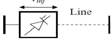
The series controller could be variable impedance, such as a reactor, capacitor, etc. or power electronics based variable source of main frequency, sub synchronous and harmonic frequencies to serve the desired need. In principle, all series controllers inject voltage in series with the line. As long as the voltage is in phase quadrature with the line current, the series controller only supplies or consumes variable reactive power. Any other relationship will involve handling of real power too.
A typical controller is Serial Synchronous Static Compensator (SSSC).
Figure 1: Series Controller b) Shunt Controllers
As in the case of series controllers, the shunt controllers may be variable impedance, variable source, or a combination of these. In principle, all shunt controllers inject current into the system at the point of connection. Even variable shunt impedance connected to the line voltage causes a variable current flow and hence represents injection of the current into the line. As long as the injected current is in phase quadrature with the line voltage, the shunt controller only supplies or consumes variable reactive power. Any other phase relationship will involve handling of real power too.
IJEDR1704131
International Journal of Engineering Development and Research (
www.ijedr.org
)
800
Figure 2: Shunt Controllerc) Combined Series-Series Controllers
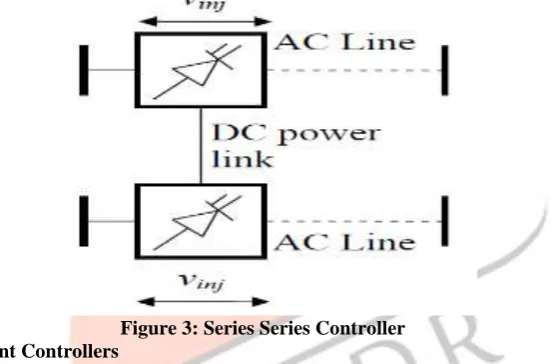
Combined series-series FACTS device is a combination of separate series FACTS devices, which are controlled in a coordinated manner, in a multiline transmission system, or it could be a unified controller. Series controllers provide independent series reactive compensation for each line and also transfer real power among the lines via the power link. The active power transmission capacity, that present a unified serial controller or line feed power controller, makes possible the active and reactive power flow balance and makes the use of transmission bigger. The real power transfer capability of the unified series-series controller, referred to as Inter Line Power Flow Controller, makes it possible to balance both the real and reactive power flow in the lines and thereby maximize the utilization of the transmission system,
In this case, the term “unified” means that the DC terminals of the converters of all the controllers are connected to achieve a transfer of active power between each other. A typical controller is the Interline Power Flow Compensator (IPFC).
Figure 3: Series Series Controller d) Combined Series-Shunt Controllers
Combined series-shunt FACTS device is a combination of separate shunt and series devices, which are controlled in a coordinated manner or one device with series and shunt elements. There could be a combination of separate shunt and series controllers, which are controlled in a coordinated manner or a Unified Power Flow Controller with series and shunt elements. In principle, combined shunt and series controllers inject current into the system with the shunt part of the controller taking care of the current while voltage in series in the line with the series part of the controller. However, when the shunt and series controllers are unified there can be real power exchange between the series and shunt controllers via the power link.
A typical controller is Unified Power Flow Controller (UPFC), which incorporating function of a filtering and conditioning becomes a Universal Power Line Conditioner (UPLC).
VI.
FACTS CONTROLLERS1.
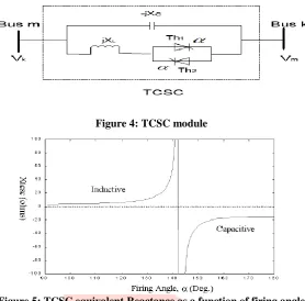
Thyristor Controlled Series Capacitor (TCSC):TCSC controllers use thyristor-controlled reactor (TCR) in parallel with capacitor segments of series capacitor bank. The combination of TCR and capacitor allow the capacitive reactance to be smoothly controlled over a wide range and switched upon command to a condition where the bi-directional thyristor pairs conduct continuously and insert an inductive reactance into the line. TCSC is an effective and economical means of solving problems of transient stability, dynamic stability, steady state stability and voltage stability in long transmission lines. TCSC, the first generation of FACTS, can control the line impedance through the introduction of a thyristor controlled capacitor in series with the transmission line. A TCSC is a series controlled capacitive reactance that can provide continuous control of power on the ac line over a wide range. The functioning of TCSC can be comprehended by analyzing the behavior of a variable inductor connected in series with a fixed capacitor.
IJEDR1704131
International Journal of Engineering Development and Research (
www.ijedr.org
)
801
A TCSC is a capacitive reactance compensator, which consists of a series capacitor bank shunted by a thyristor TCR in order to provide a smoothly variable series capacitive reactance.Figure 4: TCSC module
Figure 5: TCSC equivalent Reactance as a function of firing angle
2.
Thyristor Controlled Phase Angle Regulator (TCPAR)The TCPAR is equipment that can control power flow in transmission lines of power system by regulating the phase angle of the bus voltage. Environment restrictions usually restrict opportunities of reinforcement through the consideration of new routes. In such a situation, FACTS controllers such as TCPAR play an important role in increasing loadability of the existing system and controlling the congestion in the network.
FACTS device like TCPAR can be used to regulate the power flow in the tie-lines of interconnected power system. When TCPAR is equipped with power regulator and frequency based stabilizer it can also significantly influence the power flow in the transient states occurring after power disturbances. In the case of simple interconnected power system, consisting of two power systems the control of TCPAR can force a good damping of both power swings and oscillations of local frequency.
3.
Static Synchronous Series Compensator (SSSC)Static Series Synchronous Compensator (SSSC) is a complementary second-generation FACTS controller, which is simply a series version of STATCOM. SSSC are not yet in commercial operation as an independent controller[10].
This compensator, called static synchronous series compensator (SSSC), can provide controllable compensating voltage over an identical capacitive and inductive range, independently of the magnitude of the line current. It is immune to classical network resonances. In addition to series reactive compensation, with an external DC power supply it can also compensate the voltage drop across the resistive component of the line impedence.The compensation of the real part of the impedence can maintain high X/R ratio even if the line has a very high degree of series compensation. Concurrent and coordinated modulation of reactive and real compensation can greatly increase power oscillation damping.
An SSSC is a series FACTS device, which uses a VSC to inject a controllable voltage in quadrature with the line current of the power network through a series connected transformer, as shown in Figure 6. This is equivalent to providing a controllable capacitive or inductive impedance compensation which is independent of the line current. A typical application of the SSSC is for power flow control. In addition, with a suitably designed damping controller, the SSSC has an excellent performance in damping low-frequency power oscillations in a power network. By coupling an additional energy storage system to the dc terminal, the SSSC can also provide simultaneous active power compensation, which further enhances its capability in power flow control, power oscillation damping, and improving transient stability.
A SSSC is a static synchronous generator operated without an external electric energy source as a series compensator whose output voltage is in quadrature with, and controllable independently of the line current for the purpose of increasing or decreasing the overall reactive voltage drop across the line and thereby controlling the transmitted electric power. The SSSC may include transiently rated energy source or energy absorbing device to enhance the dynamic behavior of the power system by additional temporary real power compensation, to increase or decrease momentarily, the overall real voltage drop across the line.
IJEDR1704131
International Journal of Engineering Development and Research (
www.ijedr.org
)
802
reactance. This emulated reactance, which can be altered by varying the magnitude of injected voltage, favorably influences the electric power flow in the transmission line.Figure 6: The basic structure of Static synchronous series compensator (SSSC)
The SSSC has the same structure as that of a STATCOM except that the coupling transformer of an SSSC is connected in series with the transmission line. This device work the same way as the STATCOM. It has a voltage source converter serially connected to a transmission line through a transformer. It is necessary an energy source to provide a continuous voltage through a condenser and to compensate the losses of the VSC. A SSSC is able to exchange active and reactive power with the transmission system. But if our only aim is to balance the reactive power, the energy source could be quite small. The injected voltage can be controlled in phase and magnitude if we have an energy source that is big enough for the purpose. With reactive power compensation only the voltage is controllable, because the voltage vector forms 90º degrees with the line intensity. In this case the serial injected voltage can delay or advanced the line current. This means that the SSSC can be uniformly controlled in any value, in the VSC working slot.
4.
Thyristor Controlled Phase Shifting Transformer (TCPST)The TCPST consists of two transformers; a shunt transformer or magnetizing transformer connected in parallel and a series transformer or booster transformer in series to the line. The current through the magnetizing transformer induces a voltage on the primary side of the booster transformer. The turn ratio of the shunt transformer is 1: n, and the turn ratio of the series transformer is 1:1. Compared to conventional PST, the mechanical tap changer is replaced by a thyristor controlled equivalent.
The purpose of the TCPST is to control the power flow by shifting the transmission angle. In general, phase shifting is obtained by adding a perpendicular voltage vector in series with a phase. This vector is derived from the other two phases via shunt connected transformers. The perpendicular series voltage is made variable with a variety of power electronics topologies. A circuit concept that can handle voltage reversal can provide phase shift in either direction. This Controller is also referred to as TCPAR. A phase shifter model can be represented by an equivalent circuit. It consists of admittance in series with an ideal transformer having a complex turn’s ratio. The series transformer injects a voltage in series with the system. The Active Power and Reactive Power injected by the series transformer is taken from the shunt transformer. For the sake of simplicity, the losses in the transformers and the converter are neglected. Thus the net complex power (Active Power and Reactive Power) exchange between the TCPS and the system is zero. The injected complex power of the series transformer depends on the complex injected voltage and the line current.
5.
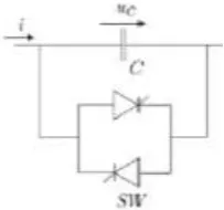
Thyristor Switched Series Capacitor ( TSSC)TSSR is an inductive reactance compensator, which consists of a series reactor shunted by a TCR to provide a stepwise control of series inductive reactance. The basic element of a TSSC is a capacitor shunted by bypass valve.The capacitor is inserted into the line if the corresponding thyristor valve is turned off, otherwise it is bypassed.
Figure 7: Basic element in a TSSC
IJEDR1704131
International Journal of Engineering Development and Research (
www.ijedr.org
)
803
inserted into the line, it will be charged by the line current from zero to maximum during the first half-cycle and discharged from maximum to zero during the successive half-cycle until it can be bypassed again.6.
Thyristor Controlled Series Reactor (TCSR)The compensator TCSR consists of variable inductance (L1) connected in series with the transmission line controlled by thyristors mounted in antiparallel and controlled by an firing angle (α) which varies between 90° and 180°, and a fixed value inductance (L2)connected in shunt.
Figure 8: Principal operation of TCSR
7.
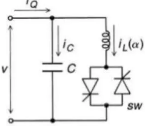
Thyristor-Controlled Inductor (TCR)TCR is a shunt-connected thyristor-controlled inductor whose effective reactance is varied in a continuous manner by partial-conduction control of the thyristor valve. TCR has been used as one of the economical alternatives of FACTS controllers. An elementary single-phase TCR is shown in Figure. The current in the reactor can be controlled from maximum to zero by the method of firing delay angle control. That is the duration of the current conduction intervals is controlled by delaying the closure of the thyristor valve with respect to the peak of the applied voltage in each half-cycle. For α = 0 the amplitude is at its maximum and for α = 90 the amplitude is zero and no current is flowing during the corresponding half cycle. Like this the same effect is provided as with an inductance of changing value[11].
Figure 9:Thyristor Controlled Reactor
8.
Thyristor Switched Reactor (TSR)A TSR has similar equipment to a TCR, but is used only at fixed angles of 90O and 180 O, i.e. full
conduction or no conduction. The reactive current iS(t) will be proportional to the applied voltage. Several TSRs can provide a reactive admittance controllable in a step-like manner. A Non-conducting thyristor varies in phase with the applied AC voltage.
9.
Static Var Compensator (SVC)The world’s first demonstration of SVC for utility application was installed in 1974, which was commercialized by General Electric (GE).A static VAR compensator (or SVC) is an electrical device for providing fast-acting reactive power on high-voltage electricity transmission networks. SVCs are part of the Flexible AC transmission system device family, regulating voltage and stabilising the system. The term "static" refers to the fact that the SVC has no moving parts (other than circuit breakers and disconnects, which do not move under normal SVC operation). Prior to the invention of the SVC, power factor compensation was the preserve of large rotating machines such as synchronous condensers. The SVC is an automated impedance matching device, designed to bring the system closer to unity power factor. If the power system's reactive load is capacitive (leading), the SVC will use reactors (usually in the form of Thyristor-Controlled Reactors) to consume VARs from the system, lowering the system voltage. Under inductive (lagging) conditions, the capacitor banks are automatically switched in, thus providing a higher system voltage. They also may be placed near high and rapidly varying loads, such as arc furnaces, where they can smooth flicker voltage. It is known that the SVCs with an auxiliary injection of a suitable signal can considerably improve the dynamic stability performance of a power system It is observed that SVC controls can significantly influence nonlinear system behavior especially under high-stress operating conditions and increased SVC gains[11].
IJEDR1704131
International Journal of Engineering Development and Research (
www.ijedr.org
)
804
opposite poled thyristors is connected in series with a fixed inductor to form a TCR module while the thyristors are connected in series with a capacitor to form a TSC module.An SVC can control the voltage magnitude at the required bus thereby improving the voltage profile of the system. The primary task of an SVC is to maintain the voltage of a particular bus by means of Reactive Power compensation (obtained by varying the firing angle of the thyristors). It can also provide increased damping to power oscillations and enhance power flow over a line by using auxiliary signals such as line AP, line RP, line current, and computed internal frequency. SVC is a shunt connected FACTS controller whose main functionality is to regulate the voltage at a given bus by controlling its equivalent reactance. Basically it consists of a fixed capacitor (FC) and a TCR. Generally they are two configurations of the SVC .
a) SVC total susceptance model:
Figure 10 (a) SVC Total Susceptance Model
b) SVC firing angle model:
Figure10. (b) SVC Firing Angle Model
10.
Fixed Capacitor Thyristor Controlled Reactor (FCTCR)FC-TCR fixed capacitor Thyristor controlled reactor-Static Var systems are used in the transmission lines for rapid control of voltage at weak point in the network. Static Var compensators(svc) are shunt connected static generated/absorbers whose outputs are varied to control voltage of the power system. The use of svc in transmission line is to provide high performance in steady state and transient voltage stability control, to dampen power swing, to reduce system loss and to control real and reactive power flow. FC-TCR type SVC is shown in figure 11.
Figure 11. Fixed capacitor Thyristor controlled reactor
In FC-TCR a, capacitor is connected in parallel with a Thyristor controlled reactor. The fixed capacitor is substituted fully or partially by a filter network that has the capacitive impedance at the fundamental frequency to generate the reactive power .In FC-TCR type Var generator consists of a variable reactor and the reactor current ( iL ) is varied by the method of firing delay
IJEDR1704131
International Journal of Engineering Development and Research (
www.ijedr.org
)
805
11.
Static synchronous compensator (STATCOM)A static synchronous compensator (STATCOM) is a regulating device used on alternating current electricity transmission networks. It is based on a power electronics voltage-source converter and can act as either a source or sink of reactive AC power to an electricity network. If connected to a source of power it can also provide active AC power. It is a member of the FACTS family of devices. Usually a STATCOM is installed to support electricity networks that have a poor power factor and often poor voltage regulation. There are however, other uses, the most common use is for voltage stability. From the power system dynamic stability viewpoint, the STATCOM provides better damping characteristics than the SVC as it is able to transiently exchange active power with the system.
The STATCOM is a shunt connected reactive power compensation device that is capable of generating and or absorbing reactive power and in which the output can be varied to control the specific parameters of an electric power system .specifically, the STATCOM is a voltage source converter that from a given input of dc voltage produces a set of 3 phase ac output voltages each in phase and with coupled to the corresponding ac system voltage through a relatively small reactance. The dc voltage is provided by an energy storage capacitor.
Figure 12. Static synchronous compensator.
12.
Distribution Static Compensator (DSTATCOM)A D-STATCOM is a shunt voltage controller, which is shown in Fig. consists of a two-level VSC, a dc energy storage device, a coupling transformer connected in shunt to the distribution network through a coupling transformer. The VSC converts the dc voltage across the storage device into a set of three-phase ac output voltages. These voltages are in phase and coupled with the ac system through the reactance of the coupling transformer. Suitable adjustment of the phase and magnitude of the STATCOM output voltages allows effective control of Active Power and Reactive Power exchanges between the D-STATCOM and the ac system. Such configuration allows the device to absorb or generate controllable Active Power and Reactive Power.
Figure.13. Schematic Digram of D-STATCOM
The shunt injected current Ish corrects the voltage sag by adjusting the voltage drop across the system impedance Zth. The
value of Ish can be controlled by adjusting the output voltage of the converter[12].
It may be mentioned that the effectiveness of the D-STATCOM in correcting voltage sag depends on the value of Zth or
IJEDR1704131
International Journal of Engineering Development and Research (
www.ijedr.org
)
806
achieved without injecting any active power into the system. On the other hand, when the value of Ish is minimized, the samevoltage correction can be achieved with minimum apparent power injection into the system.
Initial application of DSTATCOM (using GTO devices) was primarily for the control of (fundamental frequency) reactive power control and voltage regulation. SVCs have been applied for this purpose earlier. A DSTATCOM has obvious advantages over a SVC. A major advantage relates to the improved speed of response, capacity for transient overload (up to one second) in addition to the improved performance at reduced voltages.
13.
Interline Power Flow Controller (IPFC)Generally, IPFC is a combination of two or more independently controllable SSSC which are solid-state VSC which inject an almost sinusoidal voltage at variable magnitude and couples via a common DC link as shown in Fig. Conventionally, series capacitive compensation fixed, thyristor controlled or SSSC based, is employed to increase the transmittable real power over a given line and to balance the loading of a normally encountered multi-line transmission system. They are controlled to provide a capability to directly transfer independent real power between the compensated lines while maintaining the desired distribution of reactive flow among the line.The fig shows the Simplified schematic of two-converter IPFC model and basic Two-Inverter IPFC respectively.
Figure 14. Simplified Schematic of Two-Converter IPFC Mode.
14.
Phase Shifting Transformer (PST):PST is one of the most brilliant of FACTS controllers which can inject a series voltage to transmission line with controlled phase angle and magnitude. The PST is mainly composed of a set of mechanical switches that change the turn ratio of transformer. Due to slow function of mechanical switches, the PST is not suitable for dynamic studies [13].
The basic schematic of PST is shown in Fig. 15, which has been in existence for many years. PST includes two injecting and exciting transformers and mechanical switches. The PST connected to secondary windings of series and shunt transformers injects a voltage with a fixed
phase to transmission network controlled by mechanical switches. Although the technology is relatively old, the PST proves to be a valuable means of control.
Figure 15. Schematic diagram of PST.
To understand the application of PST, Shunt & series Transformer combination (Indirect Asymmetrical PST) is a type of PST is employed where the Control voltage of each phase from the shunt transformer is fed to a series transformer . The Control voltage can be varied using Tap Changer provided on Shunt Transformer. The tap changer could be static with thyristor control, which will address transient issues however will also introduce harmonics and requires filters. The voltage difference between the voltages on the secondary sides of the shunt transformers corresponding to the first phase and the one corresponding to the second phase is then a voltage in quadrature with the voltage of the third phase. This voltage difference is added in series with the third phase by means of a series transformer. The result is a voltage phase and magnitude shift of the third phase. The same principle is used for all three phases.
Types of Phase Shifting Transformer
PSTs can be designed in different forms and can be classified by these Characteristics:
Direct PSTs are based on one three phase core. The phase shift obtained by connecting the winding in an appropriate manner. • Indirect PSTs are based on construction with two separate transformers, one variable tap exciter to regulate the amplitude of the quadrature voltage and one series transformers to inject the quadrature voltage in the right phase.
• Asymmetrical PSTs create an output voltage with an altered phase angle and amplitude compared to the input voltage. • Symmetrical PSTs create an output voltage with an altered phase angle compared to the input voltage, but with the same amplitude.
IJEDR1704131
International Journal of Engineering Development and Research (
www.ijedr.org
)
807
2. Direct Symmetrical PSTs3. Indirect Asymmetrical PSTs 4. Indirect Symmetrical PSTs
15.
Unified power flow controller (UPFC)The UPFC is the most versatile and complex of the facts devices, combining the features of the STATCOM and SSSC. Unified power flow controller (UPFC) is used to control the power in the transmission systems by controlling the impedance, voltage magnitude and phase. The basic structure of UPFC consists of two voltage source converters (VSI), where one converter is connected in parallel to the transmission line (STATCOM) while the other is in series with the transmission line (SSSC).
It is based on the back to back voltage source converter arrangement in which one converter is in series and the other is in shunt with the transmission line and both the converters are operated from a common dc link provided by a dc storage capacitor [14]. This arrangement functions as an ideal ac to ac power converter in which the real power can freely flow in either direction between the ac terminals of the two converters each converter can independently generates or absorbs reactive power at its own ac output terminal .The function of converter 1 is to supply or absorb the real power demanded by converter 2 at the common dc link to support the real power exchange resulting from the series voltage injection .The dc link demand of converter 2 at the common dc link to support the real power exchange resulting from the series voltage injection. The dc link power demand of converter is converted back to ac by converter 1 and coupled to the transmission line by shunt connected transformer .converter 1 can also generate and absorb controllable reactive power to provide independent shunt reactive compensation for the line . The UPFC primarily injects a voltage in series with the line whose phase angle can vary between 0 to 2π with respect to the terminal voltage and whose magnitude can be varied from 0 to defined maximum value. The shunt inverter is operated in such a way as to demand this dc terminal power (positive or negative) from the line keeping the voltage across the storage capacitor constant so, the net real power absorbed from the line by the UPFC is equal only to the losses of the inverters and their transformers .The remaining capacity of the shunt inverter can be used to exchange reactive power with the line so as to provide a voltage regulation at the connection point .The two converters can work independently of each other by separating the dc side so, in that case the shunt inverter is operating as a STATCOM that generates or absorbs reactive power to regulate the current flow, and hence the power flow in a transmission line.
Figure16. Unified Power Flow Controller.
16.
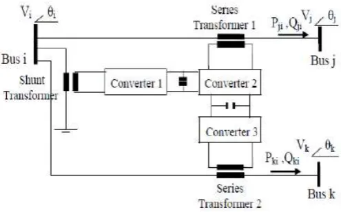
Generalized Unified Power Flow Controller (GUPFC)IJEDR1704131
International Journal of Engineering Development and Research (
www.ijedr.org
)
808
Figure17. Basic Circuit Arrangement of GUPFC17.
Hybrid Flow Controller (HFC):HFC that is introduced as a hybrid compensator is formed of a mechanically switched shunt capacitor, a mechanically switched phase-shifting transformer, and multimodule series-connected thyristor-switched capacitors and inductors . Its operation is similar to that of UPFC with some advantages such as cost effectiveness. In the structure of HFC, the PST is less effective to control dynamic power flow and the function of phase shifting and voltage regulating are with some drawbacks. Therefore, RHFC has been introduced as a new member of FACTS controller.The basic schematic of the HFC is shown in Fig. 5 [3,8].
Figure18. Schematic diagram of HFC
18.
SEN TRANSFORMER (ST)Sen Transformer (ST) uses a shared magnetic link between primary and secondary windings as shown in Fig. A three-phase voltage is applied in shunt to three primary windings that are Y-connected and placed on each limb of a three-limb, single-core transformer. On the secondary side, three induced voltages from three windings that are placed on three different limbs are combined, through series connection of the associated windings, to produce the compensating voltage for each phase. The number of active turns in the three windings can be varied with the use of LTCs. As a result, the composite voltage becomes variable in magnitude and variable in phase angle in the range of 0º and 360º. The ST uses a transformer and LTCs to create a compensating voltage that is at any angle with the prevailing line current and, therefore, acts as virtual impedance that enhances the controllability in an electric power transmission system by voltage regulation, phase angle regulation, line impedance regulation, fault-current limitation, and much more, all in one unit.
Figure 19. Sen Transformer
IJEDR1704131
International Journal of Engineering Development and Research (
www.ijedr.org
)
809
coupling transformers – in the UPFC.The ST uses a transformer and mechanical LTCs that are proven to be reliable. Its dynamic performance is limited by the speed of operation of the mechanical LTCs, which is in seconds that is acceptable in most utility applications. If faster response is desired, the mechanical LTCs can be upgraded with power electronics-based LTCs as in the Thyristor- Controlled Sen Transformer (TCST).19.
Rotary Hybrid Flow Controller (RHFC):RHFC has been introduced as a new member of FACTS controller. Structurally, an RHFC is composed a Rotary Phase-Shifting Transformer (RPST), a multimodule Thyristor-Switched Series Capacitor (TSSC), a multimodule Thyristor-Switched Series Reactor (TSSR) and a Mechanically-switched Shunt Capacitor (MSC). RPST is the main component of RHFC and the transformer characteristics of its windings prepare a rapid dynamic response and a low time constant[15].
The RHFC consist of a RPST, a multimodule TSSC, a multimodule TSSR and a conventional MSC. A model of RHFC is shown in Fig. 20, where it is installed between buses i and j in a transmission line. The RPST is the subsystem of RHFC which provides secondary three phase voltages on the rotor its module is proportional to that of primary stator voltages. The schematic of stator and rotor windings of RPST and the phase shifting angle of rotor windings shifted by angle β with respect to stator windings have been shown in Fig.21
Figure20. RHFC structure
The basic function of RPST is to provide a continuous and rapid control of RHFC in both static and dynamic conditions. Also, the series transformer injects a controlled voltage in series with the transmission line and the shunt transformer provides input voltage to the RPST. In addition, for adjusting the line series reactance and preventing overflow TSSC and TSSR are augmented with RPST to form an RHFC.
Figure21. Stator and rotor windings of RPST
20.
Amalgam Power Flow Controller (APFC):Considering the limitations of different FACTS devices, proposes an amalgam power flow controller (APFC) which consists of large rating SEN transformer (ST) and small rating distributed power flow controller (DPFC). It is amalgamation of attributes of both devices. The major contributions of APFC are:
• Due to robustness of ST and elimination of common DClink increase reliability and security.
• Cost effectiveness since size of DC battery/ capacitor required to supply reactive power is reduced as now reactive power can be exchanged through SEN transformer.
• Fast response and continuous control of power flow.
• Common excitation winding of DPFC and ST, thereby eliminating the need of additional transformer and saving the cost.
IJEDR1704131
International Journal of Engineering Development and Research (
www.ijedr.org
)
810
Figure22. Proposed APFC configurationThe DPFC is composed of independent static synchronous compensator (STATCOM) and static synchronous series compensators (SSSC). All the converters have their own capacitors and separate DC links. The real power is exchanged between series and shunt converters through the transmission line at the 3rd harmonic frequency. To circulate the real power of 3rd harmonic frequency between the converters, star-delta transformers are connected at each side of the transmission line as shown in Figure 23.
Figure23 APFC schematic single line diagram
HPF is the acronym of high-pass filter and it can be used to block fundamental frequency components and allows third harmonic components to pass, thereby providing a return path for the third harmonic component. Except this, the working principle of DPFC is similar to UPFC. SEN transformer (ST) is a three phase transformer with a star connected primary winding and nine secondary windings. The excitation winding for ST and shunt converter of DPFC is same, thereby eliminating the need of additional transformer and thus reducing the cost.
The voltage and impedance-regulating unit constitute of the nine secondary windings (a1, a2, and a3 on the core of A-phase, b1, b2, and b3 on the core of B-A-phase, c1, c2, and c3 on the core of C-phase) connected by the tap changers.Therefore, the compensating voltage injected by ST in phase A, is the phasor sum of the voltages across the secondary windings a1, b1, and c1. Similarly, the voltage injected in phase B and C is also derived from all the phases. Variation
in the magnitude and phase-angle of the compensating voltage can be accomplished by varying the tap-settings.The SEN transformer is composed of conventional PAR and VRT. It can exchange both active and reactive power. As reactive power can be exchanged through series and shunt transformer of ST, the size of DC battery/ capacitor required in series converter of DPFC is reduced. The single phase, schematic diagram of the proposed APFC is shown in Figure 23.
The resistances RSE
C1 ,RSEC2 , and RSHC shown across the capacitors of SSSC1, SSSC2,and shunt converter are
representatives of their switching losses. RSEeq
C1 , RSEeqC2 , and RSHeqC in parallel with VSE1, VSE2 and VSH are the equivalent
IJEDR1704131
International Journal of Engineering Development and Research (
www.ijedr.org
)
811
VII.
Different Types Of Facts Controller With Technical Contribution: Table 1Sr no FACTS controllers Technical contribution
1. Static synchronous Compensator (STATCOM)
Voltage control VAR compensation Transient and dynamic Stability
Voltage stability Damping oscillations
2. Static VAR Compensator (SVC,TSC,TCR)
Voltage control VAR compensation Transient and dynamic Stability
Voltage stability Damping oscillations
3. Static synchronous series Compensator (SSSC)
current control Transient and dynamic Stability
Voltage stability Damping oscillations
4. Thyristor Controlled series Compensator (TCSC/TSSC)
current control Transient and dynamic Stability
Voltage stability Damping oscillations
5. Unified power flow controller (UPFC)
Active and reactive power control Voltage control
VAR compensation Transient and dynamic Stability
Voltage stability Damping oscillations
6. Interline power flow controller (IPFC)
Voltage control Reactive power control Transient and dynamic Stability
Voltage stability Damping oscillations
7. Amalgam power flow controller (APFC)
Controls power flow in a network but also increases the reliability and security of power systems.
VIII.
A. FACTS ApplicationFACTS controllers can be used for various applications to enhance power system performance. One of the greatest advantages of using FACTS controllers is that it can be used in all the three states of the power system, namely:
(1) Steady state, (2) Transient and
(3) Post transient steady state.
However, the conventional devices find little application during system transient or contingency condition. 1. Steady State Application
Various steady state applications of FACTS controllers includes voltage control (low and high), increase of thermal loading, post-contingency voltage control, loop flows control, reduction in short circuit level and power flow control. SVC and STATCOM can be used for voltage control while TCSC is more suited for loop flow control and for power flow control.
IJEDR1704131
International Journal of Engineering Development and Research (
www.ijedr.org
)
812
• Available Transfer Capability (ATC) Improvement• Loading Margin Improvement • Congestion Management
• Reactive Power and Voltage Control 1.1. Congestion Management
Congestion management is a serious concern for Independent System Operator (ISO) in present deregulated electricity markets as it can arbitrarily increase the prices and hinders the free electricity trade. FACTS devices like TCSC, TCPAR (Thyristor Controlled Phase Angle Regulator) and UPFC can help to reduce congestion, smoothen locational marginal prices (LMP) and to increase the social welfare by redirecting power from congested interface to under-utilized lines.
1.2. ATC Improvement
In many deregulated market, the power transaction between buyer and seller is allowed based on calculation of ATC. Low ATC signifies that the network is unable to accommodate further transaction and hence does not promote free competition. FACTS controllers like TCSC, TCPAR and UPFC can help to improve ATC by allowing more power transactions. 1.3. Reactive Power and Voltage Control
The use of shunt FACTS controllers like SVC and STATCOM for reactive power and voltage control is well known.
1.4. Loading Margin Improvement
Several blackouts in many part of the world occur mainly due to voltage collapse at the maximum loadability point. Series and shunt compensations are generally used to increase the maximum transfer capabilities of power networks. The recent advancement in FACTS controllers have allowed them to be used more efficiently for increasing the loading margin in the system.
1.5. Power Flow Balancing and Control
FACTS controllers, especially TCSC, SSSC and UPFC, enable the load flow on parallel circuits and different voltage levels to be optimized and controlled, with a minimum of power wheeling, the best possible utilization of the lines, and a minimizing of overall system losses at the same time.
2. Dynamic Application
Dynamic application of FACTS controllers includes transient stability improvement, oscillation damping (dynamic stability) and voltage stability enhancement. One of the most important capabilities expected of FACTS applications is to be able to reduce the impact of the primary disturbance. The impact reduction for contingencies can be achieved through dynamic voltage support (STATCOM), dynamic flow control (TCSC) or both with the use of UPFC.
• Dynamic Voltage Control • Oscillation Damping
• Transient Stability Enhancement
• Subsynchronous Resonance (SSR) Elimination • Power Systems Interconnection
2.1. TRANSIENT STABILITY ENHANCEMENT
Transient instability is caused by large disturbances such as tripping of a major transmission line or a generator and the problem can be seen from the first swing of the angle. FACTS devices can resolve the problem by providing fast and rapid response during the first swing to control voltage and power flow in the system.
2.2. OSCILLATION DAMPING
Electromechanical oscillations have been observed in many power systems worldwide and may lead to partial power interruption if not controlled. Initially, power system stabilizer (PSS) is used for oscillation damping in power system. Now this function can be more effectively handled by proper placement and setting of SVC, STATCOM and TCSC.
2.3. DYNAMIC VOLTAGE CONTROL
Shunt FACTS controllers like SVC and STATCOM as well as UPFC can be utilized for dynamic control of voltage during system contingency and save the system from voltage collapse and blackout.
2.4. SSR ELIMINATION
Subsynchronous resonance (SSR) is a phenomenon which can be associated with series compensation under certain adverse conditions. TCSC have dynamic characteristics that differ drastically from conventional series capacitors especially at frequencies outside the operating frequency range and hence is used in Stöde, Sweden for the elimination of SSR in the power system.
2.5. POWER SYSTEM INTERCONNECTION
Interconnection of power systems is becoming increasingly widespread as part of power exchange between countries as well as regions within countries in many parts of the world. There are numerous examples of interconnection of remotely separated regions within one country. Such are found in the Nordic countries, Argentina and Brazil. In cases of long distance AC transmission, as in interconnected power systems, care has to be taken for safeguarding of synchronism as well as stable system voltages, particularly in conjunction with system faults. With series compensation, bulk AC power transmission over distances of more than 1,000 km are a reality today and has been used in Brazil north south interconnection. With the advent of TCSC, further potential as well as flexibility is added to AC power transmission.
3. APPLICATION IN DEREGULATED ENVIRONMENT
IJEDR1704131
International Journal of Engineering Development and Research (
www.ijedr.org
)
813
capacity that may belong to some other utility and hence foreclose beneficial transactions through that line. Utilities can also make use of FACTS controllers in their tie lines, either to shield it from the neighboring effects, such as wheeling transactions or to participate in such transaction. FACTS devices can also be implemented to ensure the economy in operation by placing it in a suitable line such that least cost generators can be dispatched more. It can also be used to reduce the losses in the system. Yet, another application is to use FACTS to relieve the congestion in the system. FACTS devices can be strategically placed such that congestion cost is reduced, curtailment is decreased and price volatility due to congestion is minimized.B. COSTS
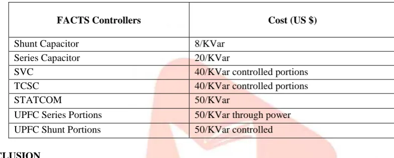
As compared to conventional devices, FACTS controllers are very expensive. The approximate cost per kVar output of various conventional devices and FACTS controllers are shown in Table 2. However, the cost per kVar decreases for higher capacity of FACTS controllers. The total cost also depends on the size of fixed and controlled portion of the FACTS controllers .The FACTS equipment cost represent only half of the total FACTS project cost. Other costs like civil works, installation, commissioning, insurance, engineering and project management constitute the other half of the FACTS project cost.
Table 2: Cost of conventional and FACTS controllers
FACTS Controllers Cost (US $)
Shunt Capacitor 8/KVar
Series Capacitor 20/KVar
SVC 40/KVar controlled portions
TCSC 40/KVar controlled portions
STATCOM 50/KVar
UPFC Series Portions 50/KVar through power
UPFC Shunt Portions 50/KVar controlled
CONCLUSION
In this paper a survey on various types of Flexible A.C. Transmission system is presented. Benefits of FACTS devices in the power flow are explained. This paper gives a general idea about the various classifications of the FACTS devices. Various FACTS controller can enhance the power system performance, both static and dynamic, considerably. Several facts device configurations have been discussed. Among all these configurations, APFC could be the most interesting solution for power quality improvement.
This paper proposed a new member of FACTS family termed as APFC for fast, reliable and cost effective solution of power flow control. It is the amalgamation of larger capacity of
SEN transformer and small capacity of DPFC. The proposed APFC can regulate the bus voltage, active and reactive power flow through the transmission line simultaneously or independently.
The APFC can also be operated as shunt or series compensator independently.
REFERENCES:
1)
Noroozian M., Andersson G., Power Flow Control by Use of Controllable Series Components, IEEE Trans. Power Del.,8(1993), No.3, 1420-1429.2)
Bindeshwar Singh, Abhiruchi, Srivastava, and Manisha “Applications of FACTS Controllers” J. Automation & Systems Engineering 8-1 (2014): 1-243)
K.S. Verma, S.N. Singh, H.O. Gupta, “Location of Unified Power Flow Controller for Congestion Management”, Electric Power System Research 58 (2001) 89-96.4)
Y Xia, YH Song, CC Liu, YX Sun, “Available Transfer Capability Enhancement Using FACTS Devices”, IEEE Trans. P. S, 20035)
C. A. Canizares, A. Berizzi, P. Marannino, “Using FACTS Controllers to Maximize Available Transfer Capability”, Bulk Power System Dynamcis and Control IVRestructuring, August 24-28, 1998, Santorini, Greece.6)
C. P. Gupta, S. C. Srivastava and R. K. Varma,“Enhancement of static voltage stability margin with reactive power dispatch using FACTS devices”, 13th PSCC in Trondheim, June 28-July 2nd, 1999.7)
R.J. Nelson, J. Bian, D.G. Ramey, T.A. Lemak, T.R. Rietman, J.E. Hill, “Transient StabilityEnhancement With FACTS Controllers”, Sixth Internatinal Conference on AC and DC Power Transmission, 29 April-3 May 1996.IJEDR1704131
International Journal of Engineering Development and Research (
www.ijedr.org
)
814
9)
N. Yang, Q. Liu, and J. D. McCalley, “TCSC Controler Design for Damping Interarea Oscillation”, IEEE Trans. PS,Vol 12, pp. 941- 946, Apr. 1997.
10)
Mr. Pradeepkumar ,S. Mahapure1, Prof. A. R. Soman “Comparison of FACTS Devices for Power System Transient Stability Improvement” International Journal Of Innovative Research In Electrical, Electronics, Instrumentation And Control Engineeringvol. 2, Issue 6, June 201411)
Satvinder Singh, Nitin Goel, Pawan Kumar “ FACTS Technologies for the Developments of Future Transmission Systems”International Journal of Emerging Trends in Engineering and Development Issue 3, Vol.2 (March 2013)12)
P. Rao, ML Crow, Z Yang, “STATCOM Control for Power System Voltage Control Applications”, IEEE Trans. PowerDelivery, 2000.
13)
Iravani M. R., Dandeno P. L., Maratukulam D., Applications of Static Phase Shifters in Power Systems, IEEE Trans.Power Del. 9(1994), No.3, 1600-1608