Research Article
Generating the Depth Map from the Motion Information of
H.264-Encoded 2D Video Sequence
Mahsa T. Pourazad, Panos Nasiopoulos (EURASIP Member), and Rabab K. Ward
Electrical and Computer Engineering Department, University of British Columbia, Vancouver, BC, Canada V6T 1Z4
Correspondence should be addressed to Mahsa T. Pourazad,[email protected]
Received 1 May 2009; Revised 28 November 2009; Accepted 10 March 2010
Academic Editor: Benoit Huet
Copyright © 2010 Mahsa T. Pourazad et al. This is an open access article distributed under the Creative Commons Attribution License, which permits unrestricted use, distribution, and reproduction in any medium, provided the original work is properly cited.
An efficient method that estimates the depth map of a 3D-scene using the motion information of the H.264-encoded 2D-video
is presented. The motion information of the video-frames captured via a single camera is either directly used or modified to approximate the displacement (disparity) that exists between the right and left images when the scene is captured by stereoscopic cameras. Then, depth is estimated based on its inverse relation with disparity. The low-complexity of this method and its compatibility with future broadcasting networks allow its real-time implementation at the receiver; thus 3D-signal is constructed at no additional burden to the network. Performance evaluations show that this method outperforms the other existing H.264-based technique by up to 1.98 dB PSNR, providing more realistic depth information of the scene. Moreover subjective comparisons of the results, obtained by viewers watching the generated stereo video sequences on a 3D-display system, confirm the superiority of our method.
1. Introduction
Three-dimensional television (3D TV) generates a com-pelling sense of physical real space for the viewers by allowing on-screen scenes to emerge and penetrate into the viewers’ space. Viewers thus feel that they are part of the scene they are watching. It is predicted that by commercialization of 3D TV applications, another revolution will take place in TV’s history (the last one being the introduction of digital video broadcasting).
The history of 3D TV can be traced back to 1920s, when the first experimental 3D TV set-up was built [1]. Since then, several attempts have been made to introduce this technology into the market. Despite the immense keenness towards 3D, the great expectations of viewers, content providers, and distributors have not yet been fulfilled. The main drawbacks were the discomfort of the viewers (headaches, eyestrain) due to the poor quality content, the low-tech display systems, and the high costs involved in the production and distribution of 3D content.
The successful introduction of 3D TV to the consumer market relies not only on technological advances but also
on the availability of a wide variety of 3D content. Thus the production of 3D-format videos is important. Equally important is the ability to convert existing 2D material to 3D format. This allows the existing popular movies and documentaries to be watched on 3D screens. Converting 2D content to 3D video streams is possible if the depth informa-tion is estimated from the original 2D video sequence. Using the depth information, 3D video content in the stereoscopic format (two temporally synchronized video streams, one for the right and another for the left eye) can be rendered from the 2D video stream, via a process known as depth image based rendering (DIBR) [2].
depth cues) such as light and shade, relative size, motion parallax, interposition (partial occlusion), textural gradient, and geometric perspective, which help the human visual system perceive the relative distance of objects within a real scene. In fact, depth map estimation techniques try to use these monocular depth cues and imitate the human visual system when estimating the distance between objects to generate binocular parallax (disparity) for the viewer.
A machine learning approach for estimating the depth map for 2D video sequences is proposed in [3]. Although the results of this approach are promising, it requires an operator to input the local depth information of some selected frames. Extraction of depth from blur has also been explored by researchers [4]. The problem in this case is that depth is not the only cause of the blur in a picture. Other reasons include motion, climate conditions, and fuzziness of objects within a scene. The estimation of depth based on the edge information has also been studied [5, 6]. Another group of researchers has utilized the motion/edge-corrected color-segmentation via a K-means algorithm to estimate the depth map [7]. This algorithm does not provide solutions when the camera is moving or when the objects have complicated motion. Also, since supervised image segmentation is implemented, when the number of objects within the scene is higher than a prespecified number, the algorithm cannot recognize the silhouette of all objects and estimate their relative distance from the camera. The study in [8] applies an unsupervised image segmentation algorithm to separate the objects. Then to decide on the depth value of each object, the proposed algorithm uses the assumption that the objects on the top part of the image are further from the viewer and the ones at the bottom part of image are closer. This assumption, however, is not valid for all video sequences.
There is a relationship between the distance of moving objects from the camera and their registered motion, which has been utilized in previous studies for motion estimation [9] and also for depth map approximation [10–12]. For objects traveling with the same speed, but different distance from a still camera, this relationship implies that the camera registers larger displacements (in pixel) for the closer objects to the camera. This approach is based on the principle known as the Pulfrich effect [13,14]. The Pulfrich effect is a psychophysical phenomenon wherein lateral motion of an object in the field of view is interpreted by the visual cortex as having a depth component, due to a relative difference in the signal timings between two eyes. To utilize this principle, the study in [10] uses a modified time difference method (MTD) to detect the horizontal motion of objects and determine the image-presentation time-delay for synthesizing a stereo pair. The MTD method does not work for images containing objects with complicated motion.
The study in [11] uses color segmentation and the KLT (Kanade-Lucas-Tomasi) feature tracker to estimate motion information. Then, the depth map is approximated based on the estimated motion information. In this approach, factors such as camera movement, scene complexity, and the magnitude of the estimated motion are used for converting the motion information of each frame into depth map.
The facts that this method is not based on existing video coding standards and it involves a relatively complex motion estimation extraction process do not allow its cost-effective real-time implementation at the decoder side. In [12], motion estimation is based on the H.264 standard but uses fixed (rather than variable) block-size matching technique. This study assumes that the motion of every object is directly proportional to its distance from the camera; thus the depth map is approximated as a constant factor of the estimated motion. Unfortunately, this is only true for a relatively small part of real life footage (when the camera is panning across a stationary scene, or a still camera captures a scene with moving objects). Otherwise, when the objects and the cam-era are both moving, there would be ambiguity in the depth estimation based on the motion information. The other issue in [12] is related to the accuracy of H.264-estimated motion vectors when they are used to derive the objects’ motion. The principle idea behind the motion estimation process in H.264/AVC and other standards relies on maximizing the compression performance and optimizing rate distortion and not on obtaining accurate estimates of the objects’ displacement in the scene. Thus, not all motion vectors can be used to accurately estimate the depth unless they reflect the objects’ displacement.
In this paper, we present an effective scheme that finds an approximate depth map of the scene using the motion information of the H.264 encoded video which is derived (at quarter pixel accuracy) via matching blocks with different sizes, where the sizes dynamically adjust to the video content. This proposal is an improved version of algorithm in [12] from two aspects: (i) generalizing previous assumption that any motion is directly proportional to distance from camera, and (ii) improving accuracy from motion vectors in H.264.
To resolve the issue regarding the accuracy of motion vectors, we propose an algorithm that examines the motion vectors and (whenever necessary) properly modifies their values, to ensure that the values of the motion vectors reflect the displacement of objects. When a moving camera captures a scene with moving objects, our proposed scheme provides a solution to estimate the motion of moving objects and uses this information to find the scene’s depth map [15]1. Since the motion estimation procedure is based on the block-matching technique, there will be depth ambiguity between the foreground and the background at the object boundaries. To solve this problem, our algorithm first adopts a color-texture segmentation algorithm known as JSEG to properly distinguish between the different object-regions [16]. Then it reevaluates and modifies the estimated values of the motion vectors of the object-boundary pixels. To ensure that the final estimated depth map is smooth and free of artifacts, our algorithm assumes that each segmented object has a unique depth value and accordingly corrects the estimated motion of the object-body pixels using the object-boundary pixels. This enhances the visual quality of 3D video that is rendered based on the estimated depth map.
Z
X
f CL
tc CR
pL
f
xL xR
pR
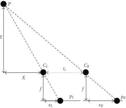
Figure1: Stereo geometry for two identical parallel cameras.
among the initial approximated depth values by using a nonlinear scaling model.
Finally, a DIBR technique is used to render the 3D videos based on the approximated depth map and 2D video. The 3D videos created using this scheme are of the stereoscopic format and are supposed to be watched on 3D TVs in the sense of stereoscopic TV. Note in this paper that by “3D TV,” we mean 3D TV in the sense of stereoscopic TV.
The rest of this paper is organized as follows.Section 2
provides background information on the principal idea behind this study. Section 3 elaborates on our 2D-to-3D conversion scheme. Section 4 presents the performance evaluation of our scheme and discusses the results in detail.
Section 5presents the conclusions.
2. Background
In 3D video capturing using stereo camera set-up, the displacement between the left and right camera images is directly related to the distance of objects from the camera. This displacement, which is known as disparity [17], creates an intrinsic feeling of depth for viewers watching stereo videos. Basically when two slightly different images are projected on the left and right eye retinas (each from a slightly different viewpoint), the brain fuses these images such that the perceived image represents everything included in two images, but in a three-dimensional format.
Figure 1illustrates how the disparity is related to depth for two identical parallel cameras.Pis a scene point whereas pLandpR are its images captured by the left (CL) and right
(CR) cameras, respectively.
For this case, assuming that the images are rectified, the disparity,d(=xR−xL), is expressed as in [17]:
d=xR−xL= f tc
Z , (1)
wherexR andxL are the coordinates of pL andpR,
respec-tively.Zis the distance of pointPfrom the cameras (depth), tcis the distance between the two cameras (baseline), and f
1 0.5 0
−0.−5 1
X(m)
hor izontal
coor dinat
e
Zfar8
7 6 5 4 3 2 1 0
Znear
Depth (m) 0
0.002 0.004 0.006 0.008 0.01
Dispar
it
y
(m)
Figure 2: Relationship between disparity and depth for sample
parallel cameras (tc=0.1 m and f=0.05 m).
is the focal length of the cameras. In a practical stereoscopic camera set-up, tc is usually equal to the average distance
between the human eyes and f is chosen based on the region of the interest within the scene.
The relationship in (1) shows that the depth of a point P (i.e.,Z) can be easily obtained if the disparity (xR−xL)
is known.Figure 2illustrates the relationship between depth and disparity. Znear and Zfar in Figure 2 are, respectively, referred to the nearest and furthest distances within the scene where still 3D perception is possible for the human visual system. In other words, only objects within [ZnearandZfar] are perceived as 3D, while the ones outside this range are viewed as 2D objects. In practical 3D TV applications,Zfar does not exceed 5 meters, since the depth of objects beyond this distance from the camera is not visually perceptible on a 3D-display. AlsoFigure 2shows that the 3D visual depth perception of the scene will not change if the viewer moves along horizontal coordinate of the scene.
For our case where the 2D scene is captured by only one camera, we shall obtain the depth Z of a moving pointP using the registered displacement that is resulted from its motion. In other words, if the left and right side frames shown inFigure 1are aligned in the time domain to form two consecutive frames, then pR and pL would be two
consecutive images of moving pointP,andxR −xL would
be the displacement between them. Since the time delay between two consecutive frames is small (as in the studies [10–12]), we assume that the displacement due to motion in the 2D case is equivalent to the disparity in a stereoscopic set-up. ThenZ, the depth of pointP, can be calculated using (1), if xR − xL is measured. The displacement (xR −xL)
between two consecutive frames could be obtained using information embedded in the motion vectors of the encoded video, assuming that f tc is constant. The following section
provides detailed information on this process.
3. Proposed Scheme
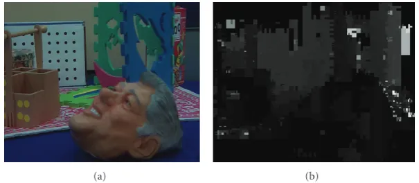
(a) (b)
Figure3: 2D video frame (a) and magnitude of estimated motion vectors (b).
procedure of the H.264 standard. Since H.264 motion vector estimation is block-based (i.e., it measures the displacement of a block and not a point or object), we propose correction steps that reevaluate and refine the estimated motion vectors in order to calculate the motion vectors for the objects within the scene. Then the resulting object motion vectors are trans-formed to depth information. The following subsections elaborate on different steps of our proposed scheme.
3.1. Motion Vector Estimation. H.264/AVC-based motion vectors (MVs) are estimated using variable block sizes of 16× 16, 16×8, 8×16, 8×8, 8×4, 4×8, and 4×4 pixels, at quarter-pixel matching accuracy [18]. These two H.264 features (variable block size and quarter-pixel matching accuracy) have been shown to yield motion vector precision that is far superior to those of any previous standards [18]. An additional advantage of using the H.264/AVC standard is the fact that H.264 has been chosen as the platform for 3D TV applications [19]. This means that the proposed scheme will be compatible with future 3D networks and players and also could be implemented at the receiver-end where the motion vectors are readily available at no additional computational cost. The existing approach in [12] forces the encoder to use only 4×4 block sizes and this will significantly decrease the compression performance and will increase the computational complexity of the overall system.
The use of small block sizes results in many wrong matches due to ambiguities and noise; however it preserves object shapes with relatively fine details. In contrast, the use of large block sizes cuts down on the wrong matches but may blur the objects boundaries [17]. For the above reasons, in our study, a variable block size is used to deal with the basic trade-offinvolved in selecting the best window size.
Figure 3(a) shows a frame from the “Orbi” sequence and
Figure 3(b) illustrates the magnitude of estimated motion vectors for this frame (the brighter the region, the higher is the magnitude and vice versa).
In H.264, depending on the application and content, some frames are selected to be compressed as I-frames. For compressing I-frames only intraprediction is utilized and no motion estimation is involved. Thus, to retrieve the motion information, we utilize the estimated motion vectors of the P-frame just after each I-frame. Since the MVs for
the P-frame are estimated in relation to the I-frame (as reference), a simple solution for finding MVs of the I-frame is to invert the MVs of the P-frame. This will give us the displacement of some overlapped blocks of the I-frame. To estimate the approximated MVs of each separate block of the I-frame, the MVs of overlapped blocks are weighted and averaged [20]. Since the use of I-frames in compression is not as common as P-frames and B-frames, an alternative solution is to estimate the MVs of an I-frame at the decoder side by implementing block matching process between the decoded I-frame and the previously decoded frame.
There also exist blocks within a P-frame or B-frame which are compressed based on intraprediction. In this case we estimate the block’s motion as the median of its neighbouring-block motion vectors. There is no provision for the intraprediction case in [12].
Multiple reference frames may be used in H.264 motion estimation for enhancing the compression performance. In this case, the estimated motion vectors do not represent the displacement of objects over two consecutive frames any more. To resolve this problem, we assume that the motion vector length is related to the reference image distance [21]. Therefore, to find the motion information between two consecutive frames, the H.264 estimated motion vectors should be rescaled proportionally, according to the distance between the used reference image and the last encoded image in the video sequence as suggested in [21].
For B-frames, forward or backward reference frames are used for predicting the blocks. To ensure that the estimated motion vectors represent the displacement of objects over consecutive frames, the motion vectors of each block should refer to the same region2 in forward or backward reference frames. If that is not the case, the block’s motion is estimated as the median of its neighbouring-block motion vectors.
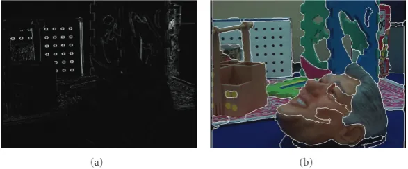
(a) (b)
Figure4: (a) Residue frame, and (b) a color-texture segmented frame of “Orbi” sequence.
information registered by the camera should be corrected accordingly.
In the camera panning case, the registered motion information for the stationary areas of the scene would be equivalent to the camera motion. These areas are often flagged as “Skip Mode” by the H.264/AVC motion estimation process. The “Skip Mode” is used for 16×16 blocks, where the motion characteristics of the block can be effectively predicted from the motion of its neighboring blocks, and the quantized transform coefficients of the block are all zeros. When a block is skipped, the transformed coefficients and the motion data are not transmitted, since the motion of the block is equivalent to the median of the motion vectors of the surrounding blocks. This median is known as the predicted motion vector (MVp) [18].
As long as there is no camera motion, the predicted motion vector of a skipped block is zero. However, when camera panning is present, all the predicted motion vectors of the skipped blocks become equal to a unique nonzero value (which represents the camera motion). Since most of the skipped blocks over the entire frame are blocks that contain background areas, our proposed scheme uses the predicted motion vector (MVp) with the maximum
occurrence to estimate the value of the camera motion. In order to find this vector for each frame, we compute the histogram of the MVps of all the skipped blocks. The
MVp that corresponds to the maximum of the histogram is
recognized as the camera (panning) motion [15]. The net motion of each object is extracted by subtracting the camera motion from the MVs of all blocks within the frame. This procedure cannot be accommodated in [12] since only 4×4 blocks are used and the size of the skip-mode blocks is 16× 16. The following code summarizes the above-mentioned procedure:
for each frame:
(1) find skipped-mode blocks with MVp∼= 0.
(2) calculate the histogram of the MVps of blocks found in 1.
(3) assign the MVp with maximum occurrence to camera panning motion.
(4) subtract camera panning motion from all the MVs within the frame.
Besides panning, camera zoom-in/out can also cause depth ambiguity. To address this issue, we check the tendency of MVs in the four corners of the frame to detect zoom in/out [11]. Then the estimated MVs are scaled accordingly. Note that zoom-in/out may cause reverse depth or eye fatigue if not corrected in the depth estimation process.
3.3. Correction of False Displacement Estimates. The criterion used in video compression standards is to optimize the rate distortion and maximize the compression performance, that is, to transmit the least number of bits. The motion vectors obtained by H.264/AVC coding are thus derived so as to minimize the compression rate and optimize rate distortion and not maximize the accuracy of the estimated motion of the objects within a scene. Thus, the matching blocks determined by a motion vector do not necessarily relate to the same part of an object in the scene. In such a case the estimated motion vectors do not accurately convey the displacement of an object; that is, they do not point to the corresponding left and right areas as defined by the disparity in a stereoscopic scenario (Figure 1).
To check if a motion vector points to the same object (or part of it) in two consecutive frames, our proposed scheme compares the motion of the block with that of its surrounding blocks. To this end, we use two predefined thresholds, Th1 and Th2. Threshold Th1 is defined as the difference between the MV of the block and the median MV of the neighboring blocks (MVm) of the same object.
Our experiments have shown that if this difference is larger than 1, then either the MV is not the actual displacement or there is a moving edge within the block. Threshold Th2, which is the measure of the variance of the residue block resulting from subtracting the present and previous frame, is then used to help us determine if the block includes the boundary pixels of a moving object. In the residual block, the edges of moving objects appear thicker and with higher density compared to static objects and the background (see
the global motion vector, simple shifting will compensate for camera motion. In the case of zooming, the frame zoomed out more (i.e., shows objects further away) is cropped and scaled to match the other frame.
We have found through performance evaluations that if the variance (i.e., Th2) is less than 1000, then there is a very high probability that there is no moving edge within the block and therefore the MV needs to be replaced by the median MV the instant neighboring blocks. Otherwise (i.e., there is a moving edge within the block), the H.264-estimated MV is correct.
Assume that the MV of a certain block is presently being estimated. To find the adjacent blocks that belong to the same object as this block, we use an unsupervised segmentation algorithm called JSEG [16]. This algorithm consists of color quantization and spatial segmentation as two separate steps. As a result, each frame is segmented into different regions based on the color and texture of the region, without any presumption about the number of objects (seeFigure 4(b)). For detailed information on this algorithm see [16].
The following code summarizes the above procedure for displacement correction:
for each frame:
(1) calculate MVdiff = abs(MV − MVp) for each block.
(2) compute residue frame as:
resFrame = abs(lumacurrent frame − lumaprevious frame)
(3) calculate the variance of each block within residue frame (resVAR).
(4) implement JSEG algorithm to segment the frame based on color and texture and distinguish different object regions.
(5) for the blocks which MVdiff > Th1 & resVar < Th2, new MVs are calculated as of median MV of their instant neighboring blocks belong to the same segmented object.
3.4. Displacement Correction of Object-Border Pixels. In this study, we use the absolute value of the horizontal component of the motion vectors (i.e., abs(MVx)) for estimating the
depth map. This is because, as explained earlier, the disparity, d(=xR−xL), which is the horizontal displacement between
the two camera images, is related to the depthZ(as shown in
Figure 1).
Since all the pixels within each matching block are assumed to have the same amount of motion, the abs(MVx)
is assigned to each pixel within the block. This assumption, however, is not valid for blocks that include both stationary background pixels and moving object pixels. For such blocks, a different procedure should be used; otherwise the resulting object borders in the constructed 3D video may appear blurred, and the small details or even entire objects may be removed.
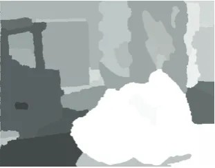
Figure5: Initial depth map after correcting the displacement of object-border pixels.
A computationally expensive solution is to perform pixel-based motion vector estimation for the object-border pixels. We propose an alternative solution which detects the border blocks with nonzero motion vectors and, then, classifies each pixel within each of these blocks as a background pixel or an object pixel. This process is based on the results of the JSEG algorithm (Section 3.3). The estimated abs(MVx) is assigned to the object pixels, while
the median of the abs(MVx) of the surrounding nonobject
pixels is assigned to the background pixels. The background pixels inside the block who have been assigned with updated abs(MVx) might be utilized in the motion correction process.
Note that if the block includes multiple segmented regions, the MV of the pixels within each segmented region is calculated as the median of MVs of pixels within the neighboring blocks which belong to the similar segmented region.
JSEG algorithm is robust, but as it can be observed from Figure 4(b), oversegmentation may occur because of the varying illumination shades [16]. For this reason, pixel classification of border blocks is further verified by calculating the average luma intensity of the corresponding block in the “residue frame” and then comparing it with the luma intensity of each pixel within the block. The luma intensity of the background pixels in the “residue frame” should be less than the calculated average. This is because the intensity of the still-background pixels in the “residue frame” is close to zero, while the intensity level of moving region edges is high.
In our method, to accurately estimate the motion vectors of the background pixels located in the central part of the blocks, we start the motion correction procedure with those background pixels that have higher number of neighbouring pixels with correct motion-values. This ensures that the median value is mainly based on correct motion values. After each iteration, the abs(MVx) values are
updated and this process continues until all motion values are corrected. After pixel-based motion vector estimation, the absolute horizontal value of the motion vector of each pixel is used to approximate its initial depth value.Figure 5
Figure6: Motion information after correcting the displacement of object-body pixels.
The following code summarizes object-border correction process:
for each object:
(1) find blocks which MVx∼= 0.
(2) label pixels within the blocks found in 1 as background-pixel or object-pixel based on the object-segmentation results by JSEG.
(3) find corresponding blocks of the ones found in 1 in the resFrame.
(4) compute average luma intensity of blocks found in 3 (resAVR)
(5) compare the luma intensity background pixels within each block found in 3 (in the resFrame) with resAVR; if it was higher than that, change the pixel’s label to object-pixel.
(6) label the corresponding pixels within the blocks found in 1 (in the current frame) according to the ones in 5.
(7) for background pixels within the blocks found in 1 recalculate motion as of median of abs(MVx) of instant-neighboring background-pixels by iteration.
(8) for the object pixels assign the estimated abs(MVx) of the block.
3.5. Displacement Correction of Object-Body Pixels. For the proposed method we assume that all the pixels of a segmented object have one depth value. Since the depth of each pixel is related to its abs(MVx), a common abs(MVx)
should be assigned to all the pixels within each object region. A simple solution is to calculate the average abs(MVx) of
all the pixels within each segmented object and assign that to all the pixels. The problem with this approach is that the H.264 motion estimation process assigns zero-value motion
(usually middle part). Thus, averaging all the abs(MVx)
will not give an accurate estimate of the motion of the segmented object. Among the pixels of a segmented object, the border/edge pixels are the ones whose motion better represents the motion of the entire object. Thus in our proposed scheme, the average of the abs(MVx) value of
border pixels is assigned to all the pixels of the segmented object and is used in estimating the object’s depth value. This may cause some detailed depth information of the central part of objects to be lost, but it will not hamper the quality of the final 3D video, since the depth information of the object boundaries is preserved [5,6].Figure 6shows the resulting motion information after correcting the displacement using the above-described process. In our study, the thickness of the object-boundary was set to four pixels at most, with the motion of a segmented object estimated as the average of the motion values of these pixels.
3.6. Perceptual Depth Enhancement. The visual depth per-ception on 3D display systems is limited to the objects within a certain range from the camera. This means that only the objects within a certain distance from camera can be seen on a 3D display system, while distant objects have no depth perception. Considering this limitation, to enhance visual depth perception of videos to be watched on 3D display, we apply a nonlinear scaling model to the abs(MVx) values,
which increases the disparity of closer objects and decreases that of distant objects. Since there is a nonlinear relation between the visual depth perception (disparity) and the distance of an object as shown in Figure 2, the proposed scaling factors are defined such that the further the object is, the smaller the scaling factor. This will increase the contrast among depth values and enhance the visual depth perception.
Our model assumes that there areN uniformly spaced depth layers within a scene, that is, within [ZnearandZfar]. A set of scaling factors is defined as
S(i)= i
N−1
1− Zfar Znear
+ Zfar
Znear 0≤i≤N−1, (2)
whereSis the scaling factor andiranges from layer 0, which corresponds toZnear(herei =0,S(0) = Zfar/Znear) to layer N−1 which corresponds toZfar(i=N−1,S(N−1)=1). To generate the enhanced depth map, the abs(MVx) values
are sorted and categorized toN uniformly spaced layers. If abs(MVx) belongs to theith category, its value is scaled as
follows:
D=abs(MVx)S(i), (3)
whereDis the enhanced disparity value andS(i) is the scaling factor at the ith depth layer. Figure 7shows the estimated depth information after perceptual depth enhancement.
Figure 7: Estimated depth map after perceptual depth enhance-ment.
problem of depth image-based rendering. In our implemen-tation, only the right-eye stream is rendered (based on the estimated depth map and the 2D video sequence), and the original 2D video is used as the left-eye stream [5,6].
4. Performance Evaluation and Discussion
The performance of our proposed depth map estimation method is tested using the 2D video sequences “Interview,” “Orbi,” “Breakdancers,” and “Ballet.” “Interview” and “Orbi” have been captured by a 3D-depth range camera (Zcam) [22], which measures the depth map of the scene while recording the 2D video. Thus, the true depth-measures of the scene are available in the form of sequences which consist of luma information only. The 2D streams of “Interview” and “Orbi” are 10-seconds and 5-seconds long, respectively, with 720×576 pixels resolution and 4 : 2 : 2 YUV format [23]. “Breakdancers” and “Ballet” are two multiview video test sequences (8 views), with 1024×768 pixels resolution, provided by Microsoft Research (MSR) group for research on multiview video coding (MVC) standard [24]. MSR also has provided the approximated depth map of the scene using stereo matching. For our experiment, the forth view video sequence of each test set and its corresponding depth map was used.
In our experiments, the motion between two consecutive frames is estimated using the H.264 encoder (JM 12.2 version). We assume that the broadcasted video is of acceptable visual quality. For this reason, in our experiments the quantization parameter was set to QP=30, which yields PSNR values above 37 dB for the tested sequences. The GOP size was set to 25 frames, and the frame structure was IBBP with 5 reference frames. We compare our method with the one presented in [12]. Since the recorded depth per each pixel is an integer number between 0 and 255, (where 255 represent the shortest distance from the camera), we assume that there are 256 depth layers for the perceptual depth enhancement step. For the same reason, the estimated depth maps of both methods are normalized as integer numbers between 0 and 255.
Figure 8shows a snap-shot of the original 2D stream, the original depth map, and the estimated depth maps generated by [12] and our approach. The experimental results have
been posted online for further review [25]. We observe that our approach yields more realistic depth estimates compared to [12]. As it is illustrated in Figure 8, unlike [12], our method can approximate the depth information of an entire object even if only partial motion information of the object is available. This is due to our object-body displacement correction procedure. The success of this procedure, how-ever, depends on the accuracy of the adopted color-texture segmentation algorithm. As it has been reported, JSEG is a robust segmentation algorithm but has some limitations (over segmentation where variation of illumination shades exists) [16]. Therefore, in order to further improve our depth estimation technique in the future, more research is needed on enhancing the segmentation procedure.
Comparing the results inFigure 8shows that both tech-niques like other motion-based depth estimation approaches fail to estimate the depth maps of static objects (e.g., the table inFigure 8(b)). According to the human visual system, which integrates different depth cues to perceive the depth, one can expect the integration of depth cues to provide more sufficient means for depth map estimation techniques [5, 6]. Improvement on retrieving depth information of static objects may require integration of our approach with other depth cues, such as sharpness, and it is recommended path for future research.
The visual quality of the resulting 3D video streams using our method and the one presented in [12] are subjectively tested against the original depth map (for Orbi & Interview) and the one acquired via stereo matching by MSR (for Breakdancers & Ballet), based on the ITU-R Recommendation BT.500-11 [26]. Eighteen people graded the videos from 1 to 100 in terms of 3D visual perception and visual picture quality in two separate experiment sets (with a short rest period between sessions). The evaluation is performed using the SeeReal,Cn 3D display. For the 3D
visual perception part of the experiment, the viewers were asked to score the videos based on the depth or volume that objects appeared to have. For the visual picture quality part, the viewers were asked to rank the videos based on picture quality, which could be affected by visual noise, blur, or various other distortions and picture instabilities (which may cause visual discomfort for viewers). Higher picture quality corresponded to higher scores.
Figure 9 illustrates the average scores of our subjective test. The original stereoscopic video had the highest scores in terms of visual picture quality and our method yielded the highest scores in terms of 3D visual perception. These tests show that the approximated depth map obtained by our method provides the best 3D visual perception and the visual picture quality of the results by our technique is higher than that of the existing method.
(a) (b) (c) (d)
(e) (f) (g) (h)
(i) (j) (k) (l)
(m) (n) (o) (p)
Figure8: 2D video sequence (a, b, c, d), recorder depth map (e, f), depth map estimated by stereo matching (g, h) estimated depth map by
[12] (i, j, k, l), and estimated depth map by our approach (m, n, o, p).
stereoscopic image would have the binocular parallax effect only for parts of moving objects (for which the H.264-based motion information is nonzero). In this case, some part of an object is perceived in 3D format and the rest in 2D, something that would increase the viewer’s visual discomfort.
The visual 3D perception improvement obtained by our method is due to two factors: the perceptual depth enhancement step, and the prominence of the depth for moving-objects.Figure 10demonstrates this effect clearly. As it can be observed, the fingers of the moving hand in image (b), rendered using the depth estimated by our technique, are longer than the ones based on the real depth map (a) and the estimated depth map by [12] (c). This effect increases the 3D
perception when the rendered videos are watched on a 3D display.
For the quantitative analysis, we chose to compare the quality of the stereoscopic videos synthesized using our technique with those of the technique proposed in [12] and the stereoscopic videos rendered from the actual (recorded) depth map. Note that since the ground truth depth maps of Breakdancers and Ballet are not available, the results for these two streams did not go under quantitative analysis.
Exist ing me tho d Our m ethod MSR p ro vi ded d epth Existing method Our m ethod MSR p ro vi ded d epth Existing method Our m ethod Ac tu al d ep th Exist ing me tho d Our m ethod Ac tu al d ep th 0 10 20 30 40 50 60 70 80 90 100 A ver age 3 D visual p er ce p tion sc o
re Interview Orbi Breakdancers Ballet
(a) Existing method Our m ethod MSR p ro vi ded d epth Existing method Our m ethod MSR p ro vi ded d epth Existing method Our m ethod Ac tu al d ep th Exist ing me tho d Our m ethod Ac tu al d ep th 0 10 20 30 40 50 60 70 80 90 100 A ver age visual pictur e q u alit y sc o
re Interview Orbi Breakdancers Ballet
(b)
Figure9: Average subjective test scores of 3D visual perception (a) and picture quality (b) for test streams. The error bars denote the 95% confidence intervals.
(a) (b) (c)
Figure10: Rendered right image based on real depth map (a), estimated depth map by our approach (b), and estimated depth map by [12] (c).
map (Figures 11(b) and 11(d)). These comparisons show how close the average quality of the estimated 3D views is to the actual ones. In this case, the higher PSNR values indicate better visual quality.Table 1shows the average PSNR values obtained for this case. We observe that our method outperforms the proposed method in [12] by 1.81 dB to 1.98 dB.
In addition to the above, we also compare the generated right views with the actual 2D video stream (Figures11(a),
11(c), and 11(e)). These comparisons show how effectively the two different techniques generate depth perception. In this case, since there is no depth present in the 2D
video stream, large PSNR values indicate failure in adding significant depth perception to the stream.Table 2shows the average PSNR values obtained for this case. As expected, we observe that the actual 3D views have the least similarity with the 2D video (no depth perception). More importantly, our method yields a PSNR value that is very similar to the actual 3D views while the PSNR value obtained by the [12] is higher than the original recorded depth. This conveys the fact that the depth map estimated by [12] creates the least 3D perception.
Our
tec
hniq
ue
Re
al
d
at
a
Existing
te
ch
niq
ue
2D video
Depth map
2D video
Recorded depth
map
2D video
Depth map
DIBR
DIBR
DIBR
Left and right videos
Left and right videos
Left and right videos
2D video
2D video
2D video
PSNR
PSNR
PSNR
PSNR
PSNR (a)
(b)
(c)
(d)
(e)
DIBR: Depth image-based rendering
Figure11: Quantitative analysis of the results.
Table1: Average PSNR comparison case Figures11(b) and11(d).
Average PSNR (dB) Interview Orbi
3D views based on our method versus actual
3D views 36.45 31.91
3D views based on existing method versus
actual 3D views 34.47 30.1
computed as
B= 1
N
(x,y)
D
x,y−Dr
x,y>Th, (4)
whereNis the number of all pixels within the depth map,D is the estimated depth map,Dr is the recorded depth map,
and Th is the error tolerance. In our experiment we use Th= 1 [27]. The results show that for our method the percentage of the correctly matched pixels is 53% (Interview) and 48% (Orbi). For [12], the percentage of correctly matched pixels is 34% (Interview) and 27% (Orbi). The comparison confirms that our method outperforms the existing method by 19% to 21%.
5. Conclusion
We present a new and efficient method that approximates the depth map of a 2D video sequence using H.264/AVC estimated motion information. This method exploits the
Table2: Average PSNR comparison case Figures11(a),11(c), and
11(e).
Average PSNR (dB) Interview Orbi
Right view rendered based on the actual
depth map versus actual 2D view 32.27 27.85
Right view rendered based on our estimated
depth map versus actual 2D view 32.38 27.89
Right view rendered based on the estimated depth map the by existing method versus actual 2D view
36.99 33.34
requirements. Performance evaluations have shown that our approach outperforms the other existing H.264 motion-based depth map estimation technique by up to 1.98 dB PSNR, that is, providing more realistic depth information of the scene.
The visual quality of our constructed 3D stream was also tested subjectively, with viewers watching the generated 3D streams on a stereoscopic display. The subjective tests showed that the 3D streams created based on our approach provided viewers with superior 3D experience. Moreover, in terms of visual quality, our approach outperforms the other existing H.264-based depth estimation method.
Acknowledgment
This work is supported by the British Columbia Innovation Council, Canada.
Endnotes
1. Part of this work was presented in the 15th International MultiMedia Modeling Conference.
2. Image segmentation is required in such cases (see
Section 3.3).
References
[1] O. Schreer, P. Kauff, and T. Sikora, “3D videocommunication:
algorithms, concepts and real-time systems,” inHuman
Cen-tered Communication, John Wiley & Sons, New York, NY, USA, 1st edition, 2005.
[2] L. Zhang and W. J. Tam, “Stereoscopic image generation
based on depth images for 3D TV,” IEEE Transactions on
Broadcasting, vol. 51, no. 2, pp. 191–199, 2005.
[3] P. Harman, J. Flack, S. Fox, and M. Dowley, “Rapid 2D to
3D conversion,” in Stereoscopic Displays and Virtual Reality
Systems IX, vol. 4660 ofProceedings of SPIE, pp. 78–86, San Jose, Calif, USA, January 2002.
[4] S.-H. Lai, C.-W. Fu, and S. Chang, “A generalized depth
estimation algorithm with a single image,”IEEE Transactions
on Pattern Analysis and Machine Intelligence, vol. 14, no. 4, pp. 405–411, 1992.
[5] W. J. Tam, A. S. Yee, J. Ferreira, S. Tariq, and F. Speranza, “Stereoscopic image rendering based on depth maps created
from blur and edge information,” inStereoscopic Displays and
Virtual Reality Systems XII, vol. 5664 ofProceedings of SPIE, pp. 104–115, San Jose, Calif, USA, January 2005.
[6] W. J. Tam, F. Speranza, L. Zhang, R. Renaud, J. Chan, and C. Vazquez, “Depth image based rendering for multiview stereo-scopic displays : role of information at object boundaries,” inThree-Dimensional TV, Video, and Display IV, vol. 6016 of
Proceedings of SPIE, pp. 75–85, Boston, Mass, USA, October 2005.
[7] Y. L. Chang, C. Y. Fang, L. F. Ding, S. Y. Chen, and L. G. Chen, “Depth map generation for 2D-to-3D conversion by
short-term motion assisted color segmentation,” inProceedings of the
IEEE International Conference on Multimedia and Expo, July 2007.
[8] C. T. Lin, C. L. Chin, K. W. Fan, and C. Y. Lin, “A novel
architecture for converting single 2D image into 3D effect
image,” in Proceedings of the 9th International Workshop on
Cellular Neural Networks and Their Applications, pp. 52–55, Hsinchu, Taiwan, May 2005.
[9] G. Cheung, A. Ortega, and T. Sakamoto, “Fast H.264 mode selection using depth information for distributed game
view-ing,” inProceedings of the IS&T/SPIE Visual Communications
and Image Processing (VCIP ’08), San Jose, Calif, USA, January 2008.
[10] T. Okino, H. Murata, K. Taima, T. Iinuma, and K. Oketani, “New television with 2D/3D image conversion technologies,” inStereoscopic Displays and Virtual Reality Systems III, vol.
2653 ofProceedings of SPIE, pp. 96–103, San Jose, Calif, USA,
January 1996.
[11] D. Kim, D. Min, and K. Sohn, “Stereoscopic video generation
method using motion analysis,” inProceedings of the 3DTV
Conference, pp. 1–4, May 2007.
[12] I. Ideses, L. P. Yaroslavsky, and B. Fishbain, “Real-time 2D to
3D video conversion,”Journal of Real-Time Image Processing,
vol. 2, no. 1, pp. 3–9, 2007.
[13] C. Pulfrich, “Die stereoskopie im dienste der isochromen und
heterochromen photometrie,” Die Naturwissenschaften, vol.
10, no. 34, pp. 735–743, 1922.
[14] D. C. Burr and J. Ross, “How does binocular delay give
information about depth?”Vision Research, vol. 19, no. 5, pp.
523–532, 1979.
[15] M. T. Pourazad, P. Nasiopoulos, and R. K. Ward, “Converting
H.264-derived motion information into depth map,” in
Pro-ceedings of the 15th International MultiMedia Modeling Con-ference (MMM ’09), pp. 108–118, Sophia-Antipolis, France, January 2009.
[16] Y. Deng and B. S. Manjunath, “Unsupervised segmentation of
color-texture regions in images and video,”IEEE Transactions
on Pattern Analysis and Machine Intelligence, vol. 23, no. 8, pp. 800–810, 2001.
[17] D. Scharstein, View Synthesis Using Stereo Vision, Lecture
Notes in Computer Science, Springer, New York, NY, USA, 1999.
[18] I. E. G. Richardson,H.264 and MPEG-4 Video Compression:
Video Coding for Next Generation Multimedia, John Wiley & Sons, New York, NY, USA, 2003.
[19] A. Vetro, P. Pandit, H. Kimata, and A. Smolic, “Joint
Multiview Video Model (JMVM) 5.0,” ISO/IEC
JTC1/SC29/WG11/N9214, Lausanne, Switzerland, July
2007.
[20] J. Kim, Y. Kim, J. Park, J. Kang, and B. Lee, “Stereoscopic conversion of two-dimensional movie encoded in MPEG-2,” inOptical Information Systems IV, vol. 6311 ofProceedings of
SPIE, pp. 631105.1–631105.8, San Diego, Calif, USA, August
2006.
[21] S. Moiron, S. Faria, P. Assuncao, V. Silva, and A. Navarro, “H.264/AVC to MPEG-2 video transcoding architecture,” in
Proceeding of the Conference on Telecommunications (ConfTele
’07), pp. 449–452, May 2007.
[22] C. Fehn, “A 3D-TV system based on video plus depth
information,” inProceedings of the 37th Asilomar Conference on
Signals, Systems, and Computers, vol. 2, pp. 1529–1533, Pacific Grove, Calif, USA, November 2003.
[23] C. Fehn, K. Sch¨u¨ur, I. Feldmann, P. Kauff, and A. Smolic,
“Proposed experimental conditions for EE4 in MPEG 3DAV,” ISO/IEC JTC1/SC29/WG11, MPEG02/M9016, Shang-hai, China, October 2002.
[26] “Methodology for the subjective assessment of the quality of television pictures,” ITU-R Recommendation BT.500-11. [27] D. Scharstein and R. Szeliski, “A taxonomy and evaluation of
dense two-frame stereo correspondence algorithms,”
![Figure 8: 2D video sequence (a, b, c, d), recorder depth map (e, f), depth map estimated by stereo matching (g, h) estimated depth map by[12] (i, j, k, l), and estimated depth map by our approach (m, n, o, p).](https://thumb-us.123doks.com/thumbv2/123dok_us/905079.1588172/9.600.61.543.73.505/figure-sequence-recorder-estimated-matching-estimated-estimated-approach.webp)
