CONTROL APPLICATION OF PV SOLAR FARM AS STATCOM FOR
INCREASING GRID POWER TRANSFER CAPACITY
PRIYANKA R. YELPALEM-Tech Electrical Power Systems Department of Electrical Engineering Rajarambapu Institute of Technology Islampur-415414, India, [email protected]
DR. H. T. JADHAV
HOD, Department of Electrical Engineering Rajarambapu Institute of Technology Islampur-415414, India [email protected]
MRS. A. A.CHANDNE
Assistant Professor, Department of Electrical Engineering, SKN Sinhgad College of Engineering Korti, Pandharpur-413308, India, [email protected]
ABSTRACT
This paper presents a new control strategy for grid integrated PV solar farm so that it can operate as STATCOM, for improving grid power transmission capacity. Solar farms produce power during day and are completely inactive in nights. The whole ratings of PV Solar Farm, which remain dormant during night, are utilized with voltage and damping control to increase power transmission capacity. The inverter capacity left after the real power production is used to perform above objective. This new control strategy of PV Solar Farm improves power transmission capacity, for which other expensive alternatives are used such as series/shunt capacitor or separate flexible AC transmission system controllers.
KEYWORDS: flexible ac transmission systems (FACTS), inverter, photovoltaic solar power system, STATCOM, damping control, reactive power control, transmission capacity,
I. INTRODUCTION
Recently renewable energy sources are the main attention for the solution to guarantee energy security and reduce greenhouse gases and also the large scale research activities are carried out in this field. PV system is becoming more popular for connecting to the grid both on large and small scale. Transmission grids are presently facing the challenges in integrating such renewable systems due to their limited power transfer capacity. To increase the available power transfer capacity of the existing lines, series compensation and FACTS devices are considered and in extreme condition there is need to construct new lines which are at very high expense. To improve power transfer capacity and also to control power flow, the line losses in transmission line will be reduced, so that it will meet the required power demand.
technology of utilizing solar farm inverter as STATCOM is called “PV-STATCOM”. This utilizes the entire solar farm inverter capacity in the night and the remainder inverter capacity after real power generation during day, both of which remains unutilized in conventional solar farm operation. The system study is carried out in MATLAB Simulink software, and results are verified with normal condition.
The section II describes the system modeling of all components required in simulation. The results of MATLAB Simulink are presented in section III. The performance of proposed control during daytime and nighttime are presented. The conclusion is presented in section IV.
II. SYSTEM MODELS
A. PHOTOVOLTAIC TECHNOLOGY-
The Photovoltaic system directly convert sunlight into electricity. PV cell is the basic device of PV system. These PV cells may be grouped to form panels or array. The output voltage and current available at the terminals PV device directly feed to the small loads such as lightning system and dc motors. PV system consists of PV modules also called PV panels which are power generating devices. For large scale PV system, number of PV modules are connected in series to form a ‘string’ and number of string having parallel with each othe to form ‘array’. Photovoltaic modules having PV cells also in series and shunt configuration connection. PV cell is nothing but the formation of pjunction from the dopping of p-type and n-type substrates that are able to produce DC current and DC voltage due to PV effect on semiconductores. Due to series and shunt combination of cells in the module there is increase in level of voltage and current.
Fig 1 Four-Parameter Model of solar cell equivalent circuit
The I-V characteristics of PV cells is described by the following equation
I=IL-ID (1)
Where L I refers to the light current and D I is the diode current. Using Shockley equation, the diode current can be expressed as
( 2)
Substitute equation (2) into equation (1), and we get
(3)
Where
(4)
(5)
(6)
In the equations above, ILR , refers to the light current at reference condition;I0,I0.R, the reverse saturation current, actual and at reference condition respectively; TC , TC.R , the cell temperature, actual and at reference condition respectively; G, GR the irradiance, actual and at reference condition respectively; q the electron charge; RS the series resistance; γ the shape factor; k the Boltzmann constant; A the completion factor; NCS the number of cells connected in series per module; NS the number of modules connected in series of the entire array; μISC the manufacturer supplied temperature coefficient of short-circuit current; and εG the material band gap energy.
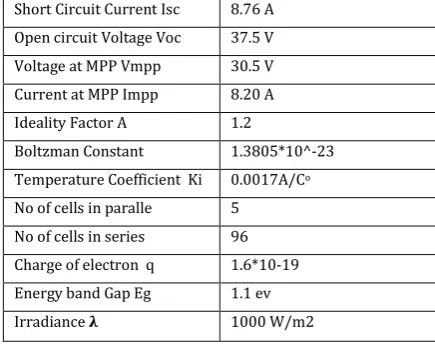
Table I: Electrical specifications of PV module Short Circuit Current Isc 8.76 A
Open circuit Voltage Voc 37.5 V
Voltage at MPP Vmpp 30.5 V
Current at MPP Impp 8.20 A
Ideality Factor A 1.2
Boltzman Constant 1.3805*10^-23
Temperature Coefficient Ki 0.0017A/Co
No of cells in paralle 5
No of cells in series 96
Charge of electron q 1.6*10-19
Energy band Gap Eg 1.1 ev
Irradiance 𝛌 1000 W/m2
B. PV INVERTER MODELING
to feed grid. Other configuration nothing but micro-inverter also called as AC module technology, in which each individual module has its own inverter and the output of all inverters are grouped together and feed it to grid. For constructing the inverter manufacturers used Metal- Oxide Semiconductor Field-Effect Transistor (MOSFET), Gate Turn Off (GTO) thyrister and Insulated Gate Bipolar Transistor (IGBT) switches. The use of IGBT switches is recent trends because of their low losses and ease of switching. For triggering the inverter switches firing pulses are generated from the inverter control. The IGBT firing pulses in the inverter are generated using various technologies such as Pulse Width Modulation (PWM), Sinusoidal Vector PWM (SVPWM) or Hysteresis Control Techniques. Among all of these techniques the PWM technique is widely used for high power PV inverter applications. For modeling control system of inverter two control schemes are widely used-Current Sourced Inverter (CSI) and Voltage Sourced Inverter (VSI) or Voltage Sourced Converter (VSC). For CSI inverter input is maintained as a constant current source using DC link Inductor. On the other hand in VSI, DC link capacitor is used for maintaining constant voltage source at the input of the inverter. Output of the inverter is controlled voltage for CSI and for VSI it is controlled current. Due to lower short circuit current contribution to the grid faults the VSI with current control strategy is preferred by industries.
C. NEED OF FACTS DEVICES
The main advantages of using FACTS devices are
Better utilization of existing transmission system assets
Increased transmission system reliability and availability
Increased dynamic and transient grid stability and reduction of loop flows
Increased quality of supply for sensitive industries Environmental benefits
D. STATCOM
Static Synchronous Compensator is a FACTS device act as shunt compensating device. A key component of solar plant is voltage source inverter which is also a core element of STATCOM. Through the power electronic processing STATCOM controls reactive power flow, it does not require additional capacitor bank like SVC that results in compact design and smaller footprint also low noise and low magnetic impact. The capacitor only used is at the DC terminal of STATCOM, which provides constant voltage. The DC power does not have any reactive component and the voltage at the DC terminals is remains constant,
therefore DC link capacitor does not participate in any reactive power exchange. STATCOM does not inject any real power to grid. Therefore DC link provides an instantaneous power circulating path to satisfy the power balance relation and converters provides circulating reactive power exchange among the phases. In practical system of STATCOM there are real power loses which are compensated from DC link capacitor, thereby reducing DC link voltage.
Fig 2. IGBT Based STATCOM Configuration
E. PROPOSED SYSTEM MODELING
Fig3. Block Diagram of Proposed System
production of real power. While in night time PV solar farm is not producing any power and hence they are completely inactive. Therefore it is disconnected from the inverter and very small amount of real power is drawn from grid to charge DC link capacitor. Then the inverter performs the function of STATCOM by providing real and reactive power to the grid.
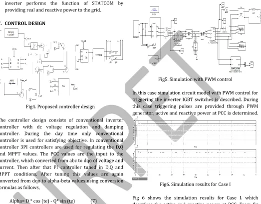
F. CONTROL DESIGN
Fig4. Proposed controller design
The controller design consists of conventional inverter controller with dc voltage regulation and damping controller. During the day time only conventional controller is used for satisfying objective. In conventional controller 3PI controllers are used for regulating the D,Q and MPPT values. The PCC values are the input to the controller, which converted from abc to dqo of voltage and current. Then after that PI controller tuned in D,Q and MPPT conditions. After tuning this values are again converted from dqo to alpha-beta values using conversion formulas as follows,
Alpha= D * cos (te) - Q* sin (te) (7) Beta= D * sin (te) + Q* cos (te) (8)
The alpha-beta values are gives for generating pulses using SVPWM for triggering inverter IGBT switches.
During nighttime the switch is closed and damping control is inserted into system. The controller operation consists of both damping and conventional control for night time. Damping controller utilizes full rating of inverter at night to provide controlled reactive power and effectively damps the oscillations. A very small amount of negative power flow from the solar farm PSolar is observed during night time. This causes losses in the inverter switches., transformer and filter resistance caused by the flow of real current from the grid into the solar farm inverter to charge DC link capacitor and maintain its voltage constant while
operating PV inverter as STATCOM with the damping controller.
III.SIMULATIONANDRESULTS
Case I- Simulation model with PWM control
Fig5. Simulation with PWM control
In this case simulation circuit model with PWM control for triggering the inverter IGBT switches is described. During this case triggering pulses are provided through PWM generator, active and reactive power at PCC is determined.
Fig6. Simulation results for Case I
Fig 6 shows the simulation results for Case I. which describes the active and reactive power at PCC. From fig we can say that there are large oscillations in the power at PCC. The active power oscillates around 0.9 MW while reactive power oscillates at near about 0.75 MVAR.
Fig 7 shows the total harmonic distortion at PCC in case I. which is very high about 10.15%.
Case II- Simulation model using proposed control
Fig8. Complete simulation of proposed system
In this case circuit is simulated using proposed control to achieve the objective of increased power transfer capacity. The PCC voltage and current are feed back to the inverter control to regulate active and reactive power of grid. The performance of this controller is observed during day time and night time.
Fig9. Simulation results for case II during day time
Fig 9 shows the results of power at PCC during day time. During day time real power is produced by solar farm and along with that power transmission is increased using proposed controller. There is increase in power which is 2 MW. Reactive power is about 1.6 MVAR.
Fig10. THD at daytime
Fig 10 shows the THD results with the proposed controller during day time, the value of THD is reduced upto 2.02% at PCC.
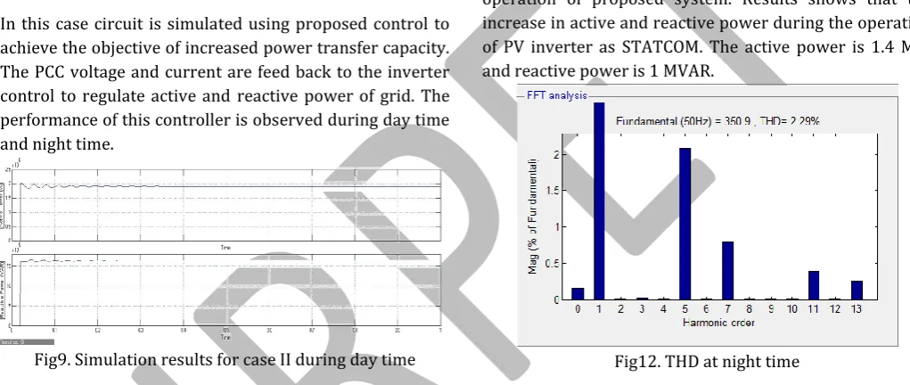
Fig11. Simulation Result for case II during night time
Fig 11 shows the simulation results during the nighttime operation of proposed system. Results shows that the increase in active and reactive power during the operation of PV inverter as STATCOM. The active power is 1.4 MW and reactive power is 1 MVAR.
Fig12. THD at night time
Fig 12 shows the result of Total Harmonic Distortion during the condition when proposed new control strategy is applied to the solar farm inverter. The THD is reduced at 2.29% as compared with case I.
IV. CONCLUSION
PV-STATCOM operation gives a new opportunity for PV solar farm to earn revenues in night time and day time in addition
to the sale of real power during the day.
REFERENCES
1) Y. Xiao, Y. H. Song, C.-C. Liu, and Y. Z. Sun, “Available transfer capability enhancement using FACTS devices,” IEEE Trans. Power Syst., vol. 18, no. 1, pp. 305–312, Feb. 2003
2) R.M.Mathurand, R.K.Varma, Thyristor Based FACTS controllers for Electrical Transmission System. Hoboken, NJ, USA: Wiley/IEEE, 2002.
3) S.A.Rahman, R.K.Varma and W. Litzenberger, “Biblography of FACTS applications for grid integration of wind and PV solar power systems: 1995-2010,IEEE working group report”, presented at the IEEEP Power Energy Soc.Gen Meeting, Detroit, MI, USA, Jul. 2011
4) Rajiv K. Varma, Vinod Khadkikar, and Ravi Seethapathy, “Nighttime Application of PV Solar Farm as STATCOM to Regulate Grid Voltage”, IEEE TRANSACTIONS ON ENERGY CONVERSION, VOL. 24, NO. 4, DECEMBER 2009.
5) Rajiv K. Varma and Vinod Khadkikar, “Utilization of Solar Farm Inverter as STATCOM”, US Provisional Patent application filed 15 Sept. 2009
6) P. Barbosa, L. Rolim, E. Watanabe and R. Hantisch, “Control strategy for grid-connected DC-AC converters with load power factor correction”,IEE Proc. Generation, Transmission and Distribution, vol.1145, no.5, pp.487-491, Sep 1998.
7) Sung-Hun Ko and Seong-Rvong Lee Hooman Dehbonei and C. V. Nayar, “A Grid-Connected Photovoltaic System with Diect Coupled Power Quality Control”, 32nd Annual Conference on IEEE Industrial Electronics, IECON 2006, pp:5203-5208.
8) Su-Won Lee, Jae-Hyung Kim, Seong-Ryong Lee, Byoung-Kuk Lee, and Chung-Yuen Won, “A Transformerless Grid-Connected Photovoltaic System with Active and Reactive Power Control”, IEEE 6th International Power Electronics and Motion Control Conference, Wuhan, China, 17-20 May 2009, pp 2178 – 2181.
9) R. K. Varma and V. Khadkikar, “Utilization of solar farm inverter as STATCOM”, U. S. Provisional Patent, Sep.15,2009.
10)R. K. Varma, S. A. ahman,and R. Seethapathy, “Novel control of grid connected photovoltaic (PV) solar farm for improving transient stability and transmission limits both
11)F.L. Albuquerque, A.J.Moraes,G.C. Guimaraes, S.M.R. Sanh Ueza, and A.R. Vaz, “Photovoltaic solar system connected to the electric power grid operating as active power and reactive power compensator”, Solar energy, Vol1.84, no.7, pp.2010.