e- ISSN: 2278-067X, p-ISSN: 2278-800X, www.ijerd.com
Volume 14, Issue 11 (November 2018), PP.11-19
Design of Closed Loop Lcl-T Resonant Dc-To-Dc Converter
Using Different Controllers
1
Dr.M. Annamalai, Member IEEE
1Department of Electrical & Electronics, Faculty of Electrical power
Nizwa College of Technology, Nizwa, INDIA Corresponding Author: Dr.M. Annamalai
ABSTRACT: The aim of this study is to simulate the closed loop controlled DC-DC converter for stand-alone wind energy system for different controllers. Wind turbines, are not always very efficient in the wind speeds that are most common to a region. Typically, wind energy systems are designed to be highly efficient in high wind speed and have a cut-off wind speed- below which no energy is captured. Therefore, for the efficient capture of wind power, turbine speed should be controlled to follow the ideal TSR, with an optimal operating point, which is different for every wind speed. The LCL-T resonant inverter system for closed loop DC-to-DC converter systems are simulated using MATLAB Simulink power system blocks for different controllers. This converter has advantages like reduced transformer size, reduced filter size and current source characteristics. The simulation studies indicate that LCL-T type for closed loop DC-DC converter can be used with stand-alone wind generator. Constant voltage can be maintained at the output of DC-to-DC converter by using a PWM rectifier at the output.
Keywords: Converters, Resonant Inverters, DC-DC Converter, MATLAB.
---
Date of Submission: 04-02-2019 Date of acceptance: 20-02-2019
---I.
INTRODUCTION
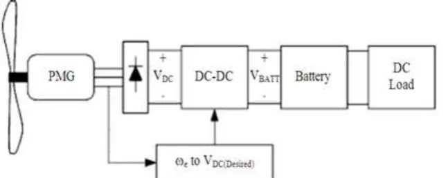
This study deals with a LCL-T resonant DC-DC converter that achieves constant wind turbine efficiency across a wide range of wind speeds for different controllers. The system is designed for use in remote location and, therefore, includes a simple control strategy and a fault- tolerant topology. The control circuit included fault detection and has been tested with a parallel redundant DC link. Previously published works demonstrated the ability of the control system to detect both open- and short-circuit converter faults and switch to a parallel converter without interruption of the supply. The literature (Kellogg et al., 1998) to (Hosseni and Moradi, 2008) does not deal with the simulation of closed loop controlled DC-to-DC converter. This study deals with closed loop controlled DC-to-DC converter. This study also compares the experimental results with the simulation results. The system represented in the Figure. 1 where VDC is a variable voltage and VBATT is a fixed DC voltage.
Figure. 1. Schematic diagram of the stand-alone wind Energy system under consideration
II.
THEORETICAL APPROACH
The fundamental equation governing the power capture of a wind turbine is Equation 1:
3
t p w
1
P AC v
2
(1)
where, Pt is turbine power, ρ is air density, A is the swept turbine area, Cp is the turbine coefficient of performance and υώ is wind speed. The coefficient of performance is a function of TSR, described by Equation 2:
m r TSR v (2)
Where, ωm is rotational speed, is the turbine radius and is wind speed. The maximum power captured by the wind turbine will occur when the TSR is approximately 7.5, corresponding to an of 0.35. A typical Cp curve shown in Figure 2.
Figure.2. Typical Cp curve
electrical energy may be maximized. Control over the rotational speed is achieved by varying the generator terminal voltage.
A simple understanding of the ideal steady-state relationship between terminal voltage and rotational speed may be obtained by considering a generator with a fundamental current in phase with terminal voltage and neglecting harmonic currents.
An approximation of the rectified dc-link voltage may be obtained using the standard equations for a three-phase full-bridge diode rectifier with line inductance. It is possible to obtain a prediction for dc-link voltage as a function of mechanical speed (or electrical generated frequency) and TSR. In the ideal case, the generator operates at the peak of the curve.
III.
DESIGN CALCULATIONS
48V/12V transformer, fs = 20 KHz, fr = 56 KHz, φ = 10µwb, Lr = 9µH, RL = 100Ω, r = 7e-4. The following assumptions are made:
(i) Saturation is neglected.
(ii) Magnetizing current is neglected Equation 3-5: Using E14.44 N 1f
We obtain N154 (3)
Using E14.44 N 1f
We obtain N113 (4)
Using fr 1 / 2 L Cr r
We obtain Cr0.75 F (5)
Using r1 / 4 3 f C RL
We obtain C 100 F (6)
The equation of inverter is as follows Equation 7-8: VO = VD for 0 < t < T/2 (7)
VO = -VD for T/2 < t < T (8)
The ripple factor of the rectifier is Equation 9: r = 1 / 4√3Fcr (9)
IV.
SIMULATION RESULTS
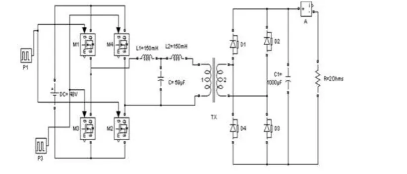
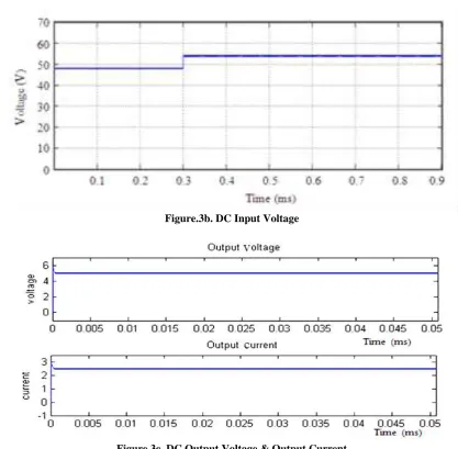
Simulation is done using MATLAB and the results are presented here. DC-DC converter is shown in figure 3a. 48V DC is converted into AC using full bridge inverter. Soft switching is obtained by introducing LCL circuit. 48V AC is stepped down to 5V AC by using step down transformer. The output of transformer is rectified by using a diode rectifier and capacitor filter. Scopes are connected to display the driving pulses, inverter output and DC output. DC input voltage is shown in figure 3b. DC output voltage and current waveforms are shown in Figure 3c. It can be seen that the output is free from ripple.
Figure.3b. DC Input Voltage
Figure.3c. DC Output Voltage & Output Current
V.
CLOSED LOOP SYSTEM FOR DIFFERENT CONTROLLERS
Figure.4a. Open Loop System with a Disturbance
Figure.4b. Input Voltage with Disturbance
Figure.4d. Output Current waveform
Figure.4e. Closed Loop System for P controllers
Figure.4g. LCL -T Resonant Converter with the PI Controller
Figure.4h. Output Voltage waveform for PI controllers
Figure.4j. LCL-T Resonant Converter with the PID Controller
Figure.4k. Output Voltage waveform for PID controllers
Figure.4l. Output current waveform for PID controllers
Table 1: Comparison of Closed Loop response of LCL converter system with PI & PID controllers LCL Converter Rise Time (Tr) Settling Time (Ts) Peak Time (Tp) Peak Voltage (Vp) Steady state error
(Ess)
PI Controller 0.015 0.61 0.44 0.22 0.016
PID Controller 0.010 0.50 0.40 0.21 0.008
VI.
DISCUSSION AND CONCLUSION
The open loop and closed loop controlled DC-DC converter systems for different controllers are simulated using MATLAB version 7.1 and the results are presented. This converter is popular due to reduced EMI, reduced stresses and high power density. The simulation studies indicate that LCL type DC-DC converter can be used with stand-alone wind generator. The simulation results closely agree with theoretical results.Constant voltage can be maintained at the output of DC-to-DC converter by using a PWM rectifier atthe output. Simulation results indicate the validity of closed loop model. From the results the PID controller is preferred for closed loop systems.
REFERENCES
[1]. Annamalai M. and Vijayakumar M., “LCL -T Resonant DC-DC Converter for standalone wind energy system”, International Journal of Engineering Research and Industrial Applications (IJERIA)” Pune – 32, Vol. 2, No.III pp. 115–124, 2009.
[2]. W. D. Kellogg, M. H. Nehrir, G. Venkataramanan, and V. Gerez, “Generation unit sizing and cost analysis for stand-alone wind, photovoltaic, and hybrid wind/PV systems,” IEEE Trans. Energy Conversion. Vol. 13, pp. 70–75, 1998.
[3]. S. Drouilhet, E. Muljadi, R. Holz, and V. Gevorgian, “Optimizing small wind turbine performance in battery charging applications,” in NREL/TP-441-7808. Golden, CO: National Renewable Energy Laboratory, 1995.
[4]. N. Yamamura, M. Ishida, and T. Hori, “A simple wind power generating system with permanent magnet type synchronous generator,” in Proc. IEEE Int. Conf. Power.
[5]. Mangesh “Analysis and design of LCL-T resonant DC to DC converter”, IEEE trans. on IE 2005.
[6]. S. Arul Daniel and N. Ammasai Gounden “A novel Hybrid Isolated Generating System based on PV fed Inverter assisted Wind-driven Induction Generators”. IEEE Transaction on energy conversion, pp 416- 422 Vol. 19, No.2, June 2004.
[7]. M. Arutchelvi and S. Arul Daniel, “Voltage Control of Autonomous hybrid generation scheme based on PV array and wind-driven induction generators”, Electric power Components and systems, pp. 759-773, Vol.34, No.7, July 2006.
[8]. M. Arutchelvi and S. Arul Daniel, “Composite controller for a hybrid power plant based on PV array fed wind-driven induction generator with battery storage”, International Journal of energy Research, pp.515-524 Vol.31, April 2007.